PIONIER a visitor instrument for the VLTI
J.-P., Berger
a,band G. Zins
aand B. Lazareff
aand J.-B. Lebouquin
aand L. Jocou
aand P.
Kern
aand R. Millan-Gabet
cand W. Traub
dand P. Haguenauer
band O. Absil
eand J.-C.
Augereau
aand M. Benisty
fand N. Blind
aand X. Bonfils
aand A. Delboulbe
aand P. Feautrier
aand M. Germain
aand D. Gillier
aand P. Gitton
band M. Kiekebusch
band J. Knudstrup
band
J.-L Lizon
band Y. Magnard
aand F. Malbet
aand D. Maurel
aand F. Menard
aand M.
Micallef
aand L. Michaud
aand S. Morel
band T. Moulin
aand D. Popovic
band K. Perraut
aand P. Rabou
aand S. Rochat
aand F. Roussel
aand A. Roux
aand E. Stadler
aand E. Tatulli
aa
LAOG,UJF,CNRS, 414 Rue de la Piscine, 38400 Saint Martin d’Heres , France;
bEuropean Southern Observatory, Paranal, Chile, Garching, Germany
c
NextSci, Caltech, USA
d
Jet Propulsion Laboratory, Pasadena California, USA
eUniversite de Li`
ege, Li`
ege, Belgium
f
Osservatorio Astrofisico di Arcetri,INAF, Arcetri, Italy
ABSTRACT
PIONIER is a 4-telescope visitor instrument for the VLTI, planned to see its first fringes in 2010. It combines four ATs or four UTs using a pairwise ABCD integrated optics combiner that can also be used in scanning mode. It provides low spectral resolution in H and K band. PIONIER is designed for imaging with a specific emphasis on fast fringe recording to allow closure-phases and visibilities to be precisely measured. In this work we provide the detailed description of the instrument and present its updated status.
Keywords: Interferometry, Aperture Synthesis, VLTI, Image Reconstruction, Integrated Optics, Young Stellar Objects, Exoplanets Debris disks, Stars
1. INTRODUCTION
Long baseline interferometry is the only tool capable to provide spatially resolved information with milli-arcsecond resolution. Over the last two decades an increasing number of astrophysical topics has taken benefit of such interferometric observations in the visible and the infrared. Interferometers such as COAST NPOI, IOTA and PTI have paved the way for larger facilities. The old visibility fitting paradigm has evolved and the richness of the interferometric observables has lead to new powerful diagnostics. Today, second generation interferometers such as VLTI, CHARA and KeckI provide spectrally dispersed visibilities, phases and closure phases. The ultimate goal for an optical interferometer, to achieve aperture synthesis imaging like in the radio domain, is now a reality. Until very recently, image reconstructions were limited to multiple systems1–3 with no extra information
added by the image. It is only very recently that J. Monnier and his team obtained the first scientific meaningful images using the MIRC instrument and four CHARA telescope on Mt Wilson. The spectacular images of the surface of Altair4or the interacting binary β Lyrae5contained unexpected features. More recently Lebouquin et
al.6 imaged the surface of the MIRA star T Lep using AMBER at the VLTI. These results are the demonstration
that aperture synthesis in the optical domain is operational and that reconstructed images bring a real added value to the standard Fourier domain complex visibility fitting.
Further author information: J.-P. Berger: [email protected]
J.-B. Le Bouquin: [email protected] G. Zins: [email protected]
VLTI second generation instruments Gravity (Gillessen et al, these proceedings) and Matisse (Lopez et al. these proceedings) will provide the astronomical community with an imaging capability respectively in the near-infrared and mid-near-infrared. But these instruments will not be operational prior to 2014.
PIONIER is a visitor instrument designed to provide VLTI, by the end of 2010, with a new observational capability that combines imaging and precision. It is operated either in H or K band with two spectral reso-lutions: broadband and R ∼ 40. It will be complementary to the current near-infrared AMBER instrument∗. The interferometric combination relies on the integrated optics (IO) technology to combine four VLTI beams (Auxiliary Telescopes or Unit Telescopes). It provides, in one observation, the simultaneous measurements of 6 visibilities and 3 + 1 closure phases. The paper is organized as follows: section 2 describes the instrumental concept, section 3 is devoted to the description of the interferometric signal and its reduction. In section 4 we discuss PIONIER science cases and we conclude in section 5 the current status of the instrument its future developments.
2. PIONIER DESCRIPTION
PIONIER is a 4 beam combining instrument that will be located on the VINCI table in the VLTI laboratory. It will be operated initially in the H band and later in the K band. The following subsections give a global overview and go into some detail of some of the instrument functions.
2.1 Subsystem description, layout and optomechanical structure
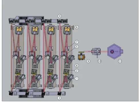
The optomechanical layout is shown on Figure 1 Functionally, it consists of the following subsystems:
• Injection and Optical Delay Unit (IOPDU). Its function is to inject the free-space beams from the VLTI into optical fibers. It includes a tip-tilt correction to optimize the fiber coupling and and a piezo-electric scanning translation to allow for optical delay sweeps of up to 800um amplitude.
• Calibration and alignment Unit (CAU). Its serves dual function: (i) to inject, as a substitute for the astronomical beams, mutually coherent beams derived from a common Tungsten source, for laboratory verification and health check purposes; (ii) to reflect, via a corner cube mirror, a reverse-propagating beam from the output of the IOBC (see below) towards the IRIS beam tracker of the VLTI observatory, for the purpose of verifying the alignment of the Pionier instrument with the IRIS reference positions.
• Integrated Optics Beam Combiner (IOBC). It takes as input, through optical fibers, the signals from the four VLTI telescopes, and delivers 6x4 outputs, consiting, for each of the six telescope pairs, of their addition with 0, π/4; π/2, and 3xπ/4 phase lags.
• Imaging Optics and Dispersion Unit (IMODU). It images the 24 outputs of the IOBC onto the camera’s focal plane, with an intermediate space where the image is at infinity, allowing the insertion of a dispersing prism and/or a Wollaston polarization diplexer.
• Camera (DET), comprising the cryostat, detector and internal electronics.
• More electronic functions –including the digitizing of the video signal– are provided by the Detector Fron-tend Electronics (DFE).
• Control system (CS) that includes hardware control of the instrument units, detector readout, quicklook and interaction with VLTI.
One sliding arm allows PIONIER to be set into three configurations:
1. free: let VLTI beams reach the instrument and operate in “science mode”; 2. mirror: send coherent signal to the instrument for internal calibration purposes;
∗
Figure 1. Pionier conceptual scheme
3. corner-cube: image the input fibers onto IRIS for alignment check.
Figure 2 shows the instrument in calibration configuration, with the modules numbered as follows: 1. Fiber optics to beam injection (via an offset parabola) for the calibration signal;
2. Folding mirror; 3. Second folding mirror;
4. Dichroic mirror. When observing the sky signals in either H or K band, the other band is transmitted to the IRIS camera for real-time monitoring of beam offsets.
5. Optical path difference modulator, consisting of a flat mirror on a piezo translation stage, with 400um mechanical travel (800um OPD).
6. Tip-tilt corrector. Also based on piezo actuators, it receives correction inputs from IRIS. Note that the correction is open-loop.
7. Shutter for obtaining dark exposures.
2.2 Detector
The detector is a PICNIC camera previously used at PTI (JPL/Caltech) and IOTA (Harvard- SAO Center for Astrophysics). Its electronics will be partially upgraded to improve the speed efficiency (see Pedretti et al.7).
One of the challenges of PIONIER will be to overcome rapid piston and coupling fluctuations and, on the UTs, to overcome the vibrations. This explains why a specific effort is put into being to sample as fast as possible the detector pixels. PIONIER detector will have two pixel distributions to read:
• broadband mode: only one row of 24 pixels is read, this should bring sensitivity and, because of increased speed, precision;
• spectrally dispersed mode: 24×7 pixels have to be read. This will allow the uv coverage to be increased and should therefore be used for imaging.
2.3 Injection and OPD Control Unit
PIONIER’s tip/tilt correction comes in addition to the one provided by the Auxiliary Telescopes (ATs) or the Unit Telescopess (UTs) and allows the additional tip/tilt contributions coming from the tunnel turbulence to be compensated for. The VLTI IRIS infrared array provides the beam angle of arrival measurements.
The optical path difference control unit has a long stroke (800 µm) that allows long opd drifts to be corrected and relaxes the need for high frequency delay line control.
2.4 Calibration and Alignment unit
The CAU unit is designed to provide:
• Four beams aligned with IRIS/MARCEL that can serve as a internal alignment reference; • Four co-phased beams that allow to record internal fringes purposes.
The CAU is made of:
• Two sources: halogen lamp and 1.55 m laser; • An integrated optics 1x4 splitter;
• Four collimators;
• Four backwards reflecting mirror
The beams provided by CAU are retractable through the use a mirrors + corner-cube motorized unit with precise positioning.
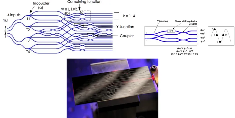
Figure 3. Top left: 4T Beam combination scheme. Top right: detail on the 2T ABCD beam combination function.
2.5 The integrated optics beam combiner
The integrated optics (IO) combiner is described in detail in Benisty et al.8 and can be seen in bottom of figure 3. The four incoming beams (top left part of figure 3) are split in three and distributed in the circuit to allow a pairwise combination to be done. A so-called static-ABCD combining cell is implemented for each baseline. It generates four phase states (almost in quadrature) that are used to extract the coherent complex visibility (top-right of figure 3). Therefore 24 outputs have to be read. This combiner can be used both in fringe-scanning mode (Vinci-like) or ABCD-like mode. There is currently one combiner available in the H band and one that is being developed in the K band.
Since we are using birefringent fibers and the IO is intrinsically birefringent differential propagation can lead to dramatic contrast reduction. The final polarization control strategy is not determined yet and several solutions are contemplated. The two favorites ones are polarization splitting using a Wollaston (the IOTA way) or active polarization compensation using free space birefringent plates. Both of them are being tested in laboratory.
2.6 Imaging Optics and Dispersion Unit
The first generation imaging and dispersing unit is the one that was used at IOTA. It images the 24 aligned outputs of the IOBC onto the detector array with or without spectral dispersion (3 or 7 spectral channels across the H band) in the perpendicular direction. Without dispersion, each output is imaged on a single pixel of the detector. A second generation optical relay unit that should accomodate the H and K band combiner is under study.
The optical layout is presented figure 4 and has the following specifications:
• System optics length of 180mm • Focal length of 110mm
• System optics clear aperture of 27mm • Collecting aperture of F/5
!
Figure 4. Optical layout of the imaging and without dispersor. Double triplet + detector window + filter wheel to scale.
Figure 5. Spot diagram of the imaging system (from left to right λ = 1.45, 1.65, 1.8µm). The pixel size (40 µm) appears as a square box.
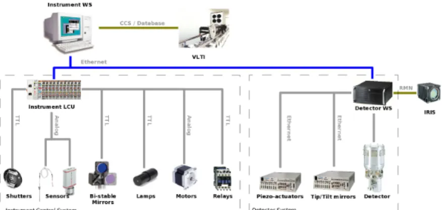
Figure 7. Schematics of PIONIER hardware/software control architecture.
• magnification of 1
• Image quality (see Fig. 5): The whole flux for each output is focused in the PICNIC camera pixel (Pixel size: 40µm).
• Image field of view of 3 mm corresponding to the output geometry (24 outputs with 160µm spacing) imaged on the detector with 3 pixels between each output image.
• System dispersion based on a zero-deviation prism to simplify the opto-mechanical implementation. It is composed of standard infrared glasses. The dispersion provided by the prism is spread out the signal over three or seven pixels across the H band according to the chosen prism.
2.7 Control and software architecture
The hardware architecture has been split into 2 parts; detector system and instrument control system. It is similar to a standard VLTI instrument with an instrument workstation (WS), an Instrument Control System (ICS) Local Control Unit (LCU) and a Detector Control System (DCS) WS, with dedicated tip/tilt and OPD correction facilities. The instrument WS is a standard Linux PC platform supported by the VLT Software. The detector WS is an industrial Linux PC platform equipped with a PCI-7300A board used to generate clock signals and to acquire detector data. It is running under the VLT Software. The instrument LCU is an Embedded PC from BECKHOFF New Automation Technology with EtherCAT/fieldbus terminals for I/O.
PIONIER electronics will be housed into a cooled cabinet close the instrument optical table. This will include the controller detector front-end electronics, the DC detector power supplies together with the detector WS, tip/tilt and scanning piezo controllers, EtherCAT, calibration lamps and control electronics for electro-mechanical devices.
The Instrument Software Package is subdivided into the following standard INS software modules:
ICS The Instrument Control Software controls all devices which belong to the instrument except the detector. It is based on standard software provided with VLT SW, called Base ICS (ICB). INS ICS will be extended to support Ethernet base fieldbus systems used for PIONIER.
DCS The Detector Control Software carries out all tasks to control the detector subsystem, to perform real-tie image processing and when needed transfer detector data to workstation. It is based on ESO NGC’s software that has been adapted to handle the PICNIC. It provides also a quicklook capability to display interferograms and first observables raw estimation (visibility, closure phase).
OS The observation software is used to coordinate the execution of an exposure for a given observing mode. It provides for setup and coordination of the various control systems such as instrument, detector, telescope and also interfaces to other software like the Archive system to archive observation data. It also completes
the final FITS header for the observation data file. The OS does not access hardware functions of the instrument. It has the knowledge of how to coordinate the control systems to perform exposures for given observing modes. It is based on Base Observation Software Stub (BOSS) provided with VLT SW. MS The Maintenance software consists in technical templates, which are used for instrument configuration,
check-out and troubleshooting.
Observing templates are executed using the standard ESO BOB tool. Dialog between PIONIER and VLTI (e.g delay lines) is achieved through the VLTI Interferometer Supervisor Software
2.8 Interface with VLTI
PIONIER is located inside the VLTI lab on the table of the late VINCI instrument. PIONIER intercepting optics can be automatically removed at any time to allow to exploit the VLTI instruments. A new automatic filling unit has been designed to accomodate as much as possible VLTI laboratory specific requests. Telescopes and delay lines are presetted using the standard VLTI software. PIONIER workstation dialogs with VLTI through ISS to off-load low-frequency OPD corrections and through RMN to get centroid information from IRIS detector.
2.9 Operating modes
Prior to the scientific operations, the following calibration are expected to take place on a daily basis on the internal sources of VLTI.
• The internal flux splitting ratio, internal contrasts and internal phase shifts can be measured by the mean of long-scan fringes obtained with the internal piezo-electric devices and with the 4T coherent source MARCEL from VLTI.
• The relative alignment between the VLTI axes and the PIONIER axes can be measured in the late afternoon with the coude beacon on the Auxiliary Telescopes. The measured offsets are stored and serve as a reference for the night.
Afterward, a typical PIONIER observation is based on the following sequence:
• VLTI preset: The new coordinates are sent to the VLTI and its subsystem. The preset time is expected to take between 2 to 5min depending on the distance and the brightness of the target. Few times in the night, the preset also includes the check of the VLTI pupil position, when the observed star is brighter than V=4. It requires about more 5min. At the end of the preset, the star is aligned and guided on the reference axis of VLTI and light should enter PIONIER. The VLTI Delay Lines are in blind trajectory. • Flux optimization: The internal tip-tilt of PIONIER are used to maximize the amount of flux in the
PICNIC camera. A small grid of offset positions are stored and fit by a Gaussian. The duration is about 5min. The relative stability between PIONIER and the VLTI axes is expected to be good. We anticipate that this optimization is required only few times during the night (if any).
• Fringe search: OPD offsets are send to the VLTI delay lines until the fringes are seen in the PIONIER real-time display. As of now, this search is manual in order to minimize the interface between PIONIER and VLTI. According to the accuracy of the VLTI pointing models, we expect this search to take between 30s to 10min depending on the difficulty of the target (first time being observed, faint, resolved, long baselines).
• Fringe recording: Once the Delay Lines offsets have been found, fringes integration is started. The fringes are temporally scanned across the coherence packet by the beam of long-range piezo-electric devices (al-though a non-scanning mode can be implemented latter on, using the simultaneous ABCD outputs). A typical exposure file contains about 200 scans. PIONIER is designed to ensure its own group delay tracking. At the end of each scan, a group delay is estimated and used in a servo loop to correct the zero positions of the scanning piezo-electric devices. The average group-delay is forwarded to the VLTI delay lines on a very slow rate (once every minute).
• Internal flux splitting ratio and dark recording: A quick sequence of shutter (one beam at a time, then all beam closed) is used to estimate the internal flux splitting ratio and the dark level of the PICNIC camera. According to the stability obtained in commissioning, this step may be skipped or not.
PIONIER performs observations in two modes: broad-band and dispersed (R ≈ 35). The switch between these modes requires to manually insert/remove the disperser prism in the collimated part of the beam after the beam combiner, see Figure 1. The broad-band mode will obviously provide the best sensitivity. It may also provide the best precision thanks to the fast capability to scan the fringes (less pixels to be read at each sample). The broad-band mode will be dedicated to imaging or limited spectral analysis.
The scientific observations will be interleaved by observations of calibration stars with known (or very small) diameters in order to estimate the value of the transfer function for the 6 visibilities and the 3 closure phases. We plane to follow a very classical calibration procedure, with a global fit of the transfer function estimates over the night. The calibration stars will be chosen among the same catalogs than for AMBER. We do not expect any special difficulty to find adequate calibration stars in the near-IR for the range of baselines offered by the VLTI. The PIONIER data reduction software will run in pseudo-real time on an offline machine in the VLTI control room. Each new file will be processed and the new visibilities and the closure phase will be added to the trend of the night. We believe this is a critical tool to optimize the scientific return of the PIONIER time. We also expect to compute the transfer function and to calibrate the scientific data in pseudo-real time (say 15 min after the files have been recorded), so that calibrated OIFITS data are available at the end of the night.
Important to notice, the Auxiliary Telescopes of VLTI cannot be relocated during the night. PIONIER will therefore make use of the same 4T configuration during a full night. We expect that 2 nights of observation at least are required to perform an image reconstruction.
3. DATA ACQUISITION
3.1 Interferometric signal description
If the interferometer was cophased, the IO combiner would allow the visibility and closure phases to be extracted from one single detector frame. Indeed the combining cell generates four outputs in almost phase quadrature. This combined with spectral dispersion, which provides an estimation of the group delay allows complex coherence to be retrieved on each baseline. But this IO combiner allows an easier, although less efficient, mean of recording coherent signal. By scanning fringes throughout the coherence envelope like in Fluor or VINCI we can recover the complex visibilities. Obviously the presence of 4 beams requires to modulate the optical paths at non redundant velocities in order to generate the fringe signal. Typically three beams will be scanned at the respectives velocities of v, −v, −2v with v obtained after a compromise between sensitivity and the necessity to freeze as much as possible the atmospheric effects. Figure 8 shows laboratory interferograms recorded on the PIONIER beam combiner (see Benisty et al. 2009 for the details). PIONIER datareduction will initially use the scanned interferograms information until a proper way to extract the coherent signal from the ABCD encoding is found. The pairwise design allows to extract the simultaneous photometric signal by a global fit to the coherent data. This simultaneity is the key to obtain precisely calibrated interferograms.
3.2 Data reduction
The data reduction software of PIONIER will convert the raw data from the detector into visibilities and phase measurements. Our strategy is directly inspired from the FLUOR, VINCI and IOTA-3T experiments. In these instruments, the scanning method associated with an estimate of the visibility in the Fourier space (integration Power Spectral Densities) provided sensitive and accurate measurements, without the need of tricky or complicated internal calibration procedures.
The raw files are stored on the instrumental machine and follows the ESO convention for VLTI data. The format has been only slightly modifed to allow the recording of each individual read of the detector pixels, and not only the final value (for instance using the DOUBLE CORRELATED mode, the 2 read are stored individually). Starting from these data, the PIONIER data reduction algorithm is composed of the following steps:
Figure 8. Top: Temporally encoded normalised interferograms (time: arbitrary units). One interferogram per baseline. Bottom: One ABCD output showing phase shifted interferograms almost in quadrature.
• Cosmetic: We perform the very basic operation that are related to the detector in order to convert the raw reads into flux measurements. The consecutive non-destructive reads are subtracted and the average bias level is removed. More advance operation may be implemented latter on, once the behavior of the detector in real operation will be better known (optimal interpolation of the non-destructive reads, filtering...). • Photometric monitoring: For each baseline, the 4 ABCD outputs are summed together (taking into account
the relative transmission) in order to obtain a measurement of the total photometry of the sum of the two considered telescopes. The result is a vector of 6 measurements of the sum of two telescopes. This system is invertible and the individual photometries of each telescope can be recovered. This procedure was commonly used on the IOTA-3T beam combiner.
• Computation of the clean fringe signals: The 24 raw signals are cleaned from the real-time photometric fluctuations of each telescope. The photometric continuum are removed and the fringe enveloppes are normalized. Then the 4 ABCD outputs of each baselines are co-added taking into account the relative phase shifts. The result is a single, clean, high-SNR interferogram per baseline. Thanks to the ABCD measurements, this interferogram is a complex quantity.
• Measurement of the visibilities: The Power Spectral Density of each interferogram is stacked until the fringe pic appears above the noise. The power in the fringe pic is a un-biased measure of the squared visibility.
• Measurement of the phase closures: We expect to implement and compare several methods to estimate the phase closures.
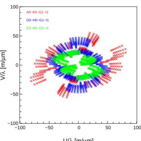
−100 −50 0 50 100 −100 −50 0 50 100 A0−K0−G1−I1 D0−H0−G1−I1 E0−H0−G0−I1 U/λ [m/µm] V/ λ [m/ µ m]
Figure 9. Typical uv coverage on a southern source with PIONIER and 3 quadruplets configuration and a spectral resolution of 100.
4. SCIENCE CASES FOR PIONIER
PIONIER has been designed to provide a low spectral resolution imaging capability to the VLTI and to push precision interferometry has far as possible. Figure 9 shows an example of uv coverage obtained using three AT quadruplets. Although many astrophysical topics will eventually benefit from its characteristics we have a core program that is related to star formation and exoplanetary studies (exozodi and planets).
Morphology of protoplanetary environments around intermediate mass pre-main sequence stars Herbig Ae Be stars, the intermediate-mass analogs of T Tauri stars have been intensively studied with optical interferometers in the last 13 years (see e.g Millan-Gabet et al.9). Consequently the view on the inner structure
of accretion disks has been substantially revisited to take into account such milli-arcsecond resolutions direct observations. The concept of “puffed-up” inner rim has been introduced. It marks the boundary in the disk where dust can no longer exist due to sublimation and forms a barrier to the photons causing altering the vertical structure of the disk. Additionally there are several evidences that matter flows through this limit to the star. Revealing the nature of the matter inside the dust sublimation limit is still an active of research. We have identified a small sample of HAeBes whose environment have been clearly resolved by the VLTI and should therefore be ideal candidates for imaging with PIONIER in order to reveal the morophology and time-variability of the inner astronomical unit near-infrared emission.
The shape of T Tauri disks If sensitivity allows it PIONIER will be used to probe the structure of the inner dust disk around T Tauri stars. While the circumstellar disks are not expected to be fully resolved the visibilities will give us access to the inner disk location while the closure phases will allow the morphology and surface brightness profile to be probed. In the best cases, it will be possible to extract the inner rim position, ellipticity and thickness. All of these are of major importance to understand the conditions for star and planet formation.
Origin, morphology and evolution of hot inner debris discs around main sequence stars The inner Solar System contains a cloud of small dust grains created when small bodies asteroids and comets collide and outgas. This dust cloud (the zodiacal disc) has long been suspected to have extrasolar analogs (exozodiacal discs), which have remained elusive until recently, when near-infrared interferometric observations revealed small (1%) excesses around several nearby stars.10, 11 These excesses have been interpreted as been due to hot, possibly transient exozodiacal dust within 1 AU from these stars. We envision to use the high-precision
visitor instrument PIONIER in order to (i) characterise the hot dust grains properties, (ii) tentatively study the inner disc morphology in bright cases, and (iii) survey young main sequence stars to study the hot dust content during the late phases of terrestrial planet formation. Given the importance of precision such observations will be preceded by an adequate commissioning program of PIONIER accuracy in order to determine its performances and proceed (or not) with the science program.
Direct detection of Hot Jupiters with infrared interferometry Closure phase is one of the most robust interferometric observables. By construction it suppresses the harmful effect of atmospheric turbulence.12 have proposed and experimented the use closure phase measurements at CHARA to spatially resolve hot jupiters which elude direct detection from single-mirror instruments. In order to achieve such a result a great deal of systematics biases has to be hunted down and understood which is far from easy. PIONIER has such an experimental program which will start with a dedicated commissioning. The success of the preliminary testing campaing will determine wether the program will continue. If succesful PIONIER will have the means to separate the flux contribution of the planet from that of its parent star and potentially obtain low spectral resolution information. From low-resolution spectra of HJs obtained with PIONIER, model fitting shall: (i) provide a measurement of their albedo and temperature, (ii) test the cloud-free assumption, (iii) constrain the heat redistribution, and (iv) detect CO and H2O species. Such major observations of the still poorly known HJs will obviously put unprecedented constraints on our understanding of planetary structure and formation.
Other studies The previous science programs bear with them some risk which is linked either to the intrinsic magnitude of the sources either to the precision requested on the interferometric observables measurements. We have therefore a bright object program centered imaging of stellar surfaces and the study of interacting binaries. However a numerous of other programs (Wolf-Rayet studies, low-mass stars diameters etc.) will be developed in the context of external collaborations.
5. CONCLUSION: STATUS AND FUTURE WORK
The principle of PIONIER has been approved by STC at spring 2009. It has the status of visitor instrument and competes with other VLTI mainstream instruments for time allocation. Proposals are submitted each semester for scientific evaluation by ESOs OPC. First commissioning and scientific lights are expected at the end of 2010 (Period 87). As of july 2010 PIONIER has been integrated in Grenoble and is undergoing preliminary testing. The current version of PIONIER only accomodates an H band combiner. An extension to the K band is highly desirable given for a number of key science cases.
REFERENCES
[1] Baldwin, J. E., Beckett, M. G., Boysen, R. C., Burns, D., Buscher, D. F., Cox, G. C., Haniff, C. A., Mackay, C. D., Nightingale, N. S., Rogers, J., Scheuer, P. A. G., Scott, T. R., Tuthill, P. G., Warner, P. J., Wilson, D. M. A., and Wilson, R. W., “The first images from an optical aperture synthesis array: mapping of capella with coast at two epochs.,” Astronomy and Astrophysics 306, L13 (Feb 1996).
[2] Benson, J. A., Hutter, D. J., Elias, N. M., Bowers, P. F., Johnston, K. J., Hajian, A. R., Armstrong, J. T., Mozurkewich, D., Pauls, T. A., Rickard, L. J., Hummel, C. A., White, N. M., Black, D., and Denison, C. S., “Multichannel optical aperture synthesis imaging of zeta1 ursae majoris with the navy prototype optical interferometer.,” Astronomical Journal v.114 114, 1221 (Sep 1997).
[3] Monnier, J. D., Traub, W. A., Schloerb, F. P., Millan-Gabet, R., Berger, J.-P., Pedretti, E., Carleton, N. P., Kraus, S., Lacasse, M. G., Brewer, M., Ragland, S., Ahearn, A., Coldwell, C., Haguenauer, P., Kern, P., Labeye, P., Lagny, L., Malbet, F., Malin, D., Maymounkov, P., Morel, S., Papaliolios, C., Perraut, K., Pearlman, M., Porro, I. L., Schanen, I., Souccar, K., Torres, G., and Wallace, G., “First results with the iota3 imaging interferometer: The spectroscopic binaries virginis and wr 140,” The Astrophysical Journal 602, L57 (Jan 2004).
[4] Monnier, J. D., Zhao, M., Pedretti, E., Thureau, N., Ireland, M., Muirhead, P., Berger, J.-P., Millan-Gabet, R., Belle, G. V., ten Brummelaar, T., McAlister, H., Ridgway, S., Turner, N., Sturmann, L., Sturmann, J., and Berger, D., “Imaging the surface of altair,” Science 317, 342 (Jun 2007). (c) 2007: Science.
[5] Zhao, M., Gies, D., Monnier, J. D., Thureau, N., Pedretti, E., Baron, F., Merand, A., ten Brummelaar, T., McAlister, H., Ridgway, S. T., Turner, N., Sturmann, J., Sturmann, L., Farrington, C., and Goldfinger, P. J., “First Resolved Images of the Eclipsing and Interacting Binary β Lyrae,” Astrophysical Journal Letters 684, L95–L98 (Sept. 2008).
[6] Bouquin, J.-B. L., Lacour, S., Renard, S., Thi´ebaut, E., Merand, A., and Verhoelst, T., “Pre-maximum spectro-imaging of the mira star t leporis with amber/vlti,” Astronomy and Astrophysics 496, L1 (Mar 2009).
[7] Pedretti, E., Millan-Gabet, R., Monnier, J. D., Traub, W. A., Carleton, N. P., Berger, J.-P., Lacasse, M. G., Schloerb, F. P., and Brewer, M. K., “The picnic interferometry camera at iota,” The Publications of the Astronomical Society of the Pacific 116, 377 (Mar 2004).
[8] Benisty, M., Berger, J.-P., Jocou, L., Labeye, P., Malbet, F., Perraut, K., and Kern, P., “An integrated optics beam combiner for the second generation vlti instruments,” Astronomy and Astrophysics 498, 601 (Apr 2009).
[9] Millan-Gabet, R., Malbet, F., Akeson, R., Leinert, C., Monnier, J., and Waters, R., “The circumstellar environments of young stars at au scales,” Protostars and Planets V , 539 (Jan 2007).
[10] Absil, O., di Folco, E., M´erand, A., Augereau, J.-C., du Foresto, V. C., Aufdenberg, J. P., Kervella, P., Ridgway, S. T., Berger, D. H., ten Brummelaar, T. A., Sturmann, J., Sturmann, L., Turner, N. H., and McAlister, H. A., “Circumstellar material in the vega inner samong the interferometric observables closure phase is one of the mosystem revealed by chara/fluor,” Astronomy and Astrophysics 452, 237 (May 2006). [11] Absil, O., di Folco, E., M´erand, A., Augereau, J.-C., du Foresto, V. C., Defr`ere, D., Kervella, P., Aufdenberg, J. P., Desort, M., Ehrenreich, D., Lagrange, A.-M., Montagnier, G., Olofsson, J., ten Brummelaar, T. A., McAlister, H. A., Sturmann, J., Sturmann, L., and Turner, N. H., “A near-infrared interferometric survey of debris disc stars. ii. chara/fluor observations of six early-type dwarfs,” Astronomy and Astrophysics 487, 1041 (Sep 2008).
[12] Zhao, M., Monnier, J. D., ten Brummelaar, T., Pedretti, E., and Thureau, N., “Closure phase studies toward direct detection of light from hot jupiters,” Exoplanets: Detection, Formation and Dynamics, Proceedings of the International Astronomical Union, IAU Symposium 249, 71 (Jan 2008).