Athena X-IFU thermal filters development status
towards the end of the instrument phase-A
Marco Barbera
*a,b, Ugo Lo Cicero
b,a, Luisa Sciortino
a, Fabio D’Anca
c, Giuseppe Lo Cicero
a,
Giancarlo Parodi
d, Salvatore Sciortino
b, Gregor Rauw
e, Graziella Branduardi-Raymont
f, Salvatore
Varisco
b, Salvatore Ferruggia Bonura
a,b, Alfonso Collura
b, Roberto Candia
b, Gaspare Di Cicca
b,
Paolo Giglio
g, Antonino Buttacavoli
a,b, Francesco Cuttaia
h, Fabrizio Villa
h, Massimo Cappi
i,
Thien Lam-Trong
i, Jean Michel Mesnager
i, Philippe Peille
i, Roland Den Hartog
l,
Jan-Willem Den Herder
l, Brian Jackson
l, Didier Barret
m, Luigi Piro
na
Dipartimento di Fisica e Chimica - Università degli Studi di Palermo (IT);
bOsservatorio
Astronomico di Palermo - Istituto Nazionale di Astrofisica (IT);
cIstituto di BioFisica U.O.S. di
Palermo - Consiglio Nazionale delle Ricerche (IT);
dBCV progetti s.r.l., Milano, (IT),
eDepartment
of Astrophysics, Geophysics & Oceanography, University of Liège (BE);
fMullard Space Science
Laboratory - Department of Space and Climate Physics – University College London (UK);
gDipartimento dell’Innovazione Industriale e Digitale - Università degli Studi di Palermo (IT);
hIstituto di Astrofisica Spaziale e Fisica Cosmica di Bologna - Istituto Nazionale di Astrofisica (IT);
i
Centre National d'Études Spatiales, Toulouse (FR);
lNetherlands Institute for Space Research –
SRON (NL);
mInstitut de Recherche en Astrophysique et Planétologie – CNRS and Universite de
Toulouse III Paul Sabatier/OMP, Toulouse (FR),
nIstituto di Astrofisica e Planetologia Spaziali -
Istituto Nazionale di Astrofisica, Roma (IT)
ABSTRACT
The X-ray Integral Field Unit (X-IFU) is one of the two instruments of the Athena astrophysics space mission approved by ESA in the Cosmic Vision 2015-2025 Science Programme. The X-IFU consists of a large array of transition edge sensor micro-calorimeters that will operate at ~100 mK inside a sophisticated cryostat. A set of thin filters, highly transparent to X-rays, will be mounted on the opening windows of the cryostat thermal shields in order to attenuate the IR radiative load, to attenuate radio frequency electromagnetic interferences, and to protect the detector from contamination.
Thermal filters are critical items in the proper operation of the X-IFU detector in space. They need to be strong enough to survive the launch stresses but very thin to be highly transparent to X-rays. They essentially define the detector quantum efficiency at low energies and are fundamental to make the photon shot noise a negligible contribution to the energy resolution budget.
In this paper, we review the main results of modeling and characterization tests of the thermal filters performed during the phase A study to identify the suitable materials, optimize the design, and demonstrate that the chosen technology can reach the proper readiness before mission adoption.
Keywords: X-ray Integral Field Unit (X-IFU), ATHENA X-ray observatory, X-ray detectors, microcalorimeters,
Transition Edge Sensors, thermal thin-film filters.
1. INTRODUCTION
The Advanced Telescope for High-Energy Astrophysics (Athena)[1] is the second Large (L2) astrophysics space mission selected by ESA in the Cosmic Vision 2015-2025 Science Program to address the Hot and Energetic Universe science theme[2]. ATHENA, whose launch is scheduled before 2030, will be equipped with a 12 m focal length grazing
*
incidence X-ray telescope based on the innovative silicon pore optics technology, capable to provide 1.4 m2 effective
area at 1 keV with an angular resolution full width at half maximum (FWHM) of 5” over a large field of view (> 40’ diameter)[3][4]. The telescope will be mounted on a moveable platform which will allow both focus adjustment and tilt to point the X-ray beam on one of the two focal plane detectors: the X-ray Integral Field Unit (X-IFU)[5][6] micro-calorimeter array, and the large Wide Field Imager (WFI)[7][8] depleted field effect transistors (DEPFET) array.
The X-IFU, based on an array of 3840 transition edge sensors (TES) microcalorimeters, will provide integral field spectroscopy in the energy range 0.2-12 keV, with an energy resolution of 2.5 eV FWHM up to 7 keV, and 5 arcsec half energy width (HEW) spatial resolution over a field of view of 5 arc minute equivalent diameter[5][6].
The X-IFU microcalorimeters will operate at a temperature close to 100 mK inside a sophisticated multi-stages detector cooling system (DCS). To allow the X-ray photons, focused by the large area Athena telescope, to reach the X-IFU detector at the focal plane, windows have to be opened on the cryostat thermal and structural shields. Thermal filters (TF) need to be mounted on such shields to attenuate the radiative heat load from warm surfaces, but they are required to be highly transparent in the X-ray energy range of interest. For this reason, the TFs need to be very thin and made of light materials, but at the same time they have to be resistant enough to withstand severe launch stresses and space environment radiations[9][10].
The TFs, beside protecting the detector from IR radiative load, have to protect the detector from molecular contamination and attenuate radio frequency (RF) generated from the spacecraft telemetry and onboard electronics. The TFs also contribute together with an optical blocking filter (OBF), mounted on a filter wheel, to reduce the optical load from bright UV/Vis astrophysical sources[11].
Large size sub-micron thickness polyimide films coated with aluminum have been successfully used in many recent missions such as Chandra[12][13] and XMM Newton[14], demonstrating reliability and long-term stability[15][16]. The same type of filters has been successfully used on rocket experiments with microcalorimeters[17], and were mounted on the Suzaku X-ray Spectrometer based on doped Si microcalorimeters[18], and onboard Hitomi[19][20]. This positive heritage guided our choice of polyimide carrier coated with aluminum as the baseline material for the design of the X-IFU TFs[9].
Athena is presently in phase-A study, both at spacecraft and instrument levels. In particular, the instrument phase-A will be completed by the end of 2018 and the mission adoption by ESA is planned on early 2021; at that time, a technology readiness level (TRL) 5 or more, according to ESA standards[21], shall be demonstrated for all relevant subsystems of the instrument.
In this paper, we give a general current status overview of the design and experimental characterization test campaigns performed to support the design consolidation of the X-IFU TFs, in view of the Preliminary Requirement Review at the end of the instrument phase-A. Three other papers presented in this conference provide more detailed information on thermal modelling[22], RF attenuation measurements[23], and mechanical tests and structural analysis[24] performed on partially representative TF samples.
In section 2 we will review the requirements the TFs have to satisfy and the drivers that have guided our design; in section 3 we present the currently investigated TF design; section 4 is dedicated to review the characterization tests performed on partially representative filter samples. The last section before the conclusions will be dedicated to describe the ongoing trade-off analysis aimed at optimizing the TF performances to fully satisfy the requirements.
2. REQUIREMENTS AND DESIGN DRIVERS
The following requirements in terms of performance and functionality, applicable throughout the life of the mission, have been identified for the X-IFU Thermal Filters and reported in the document “X-IFU Optical Thermal Blocking Filters Requirements Document” prepared by CNES and presently available as a draft[25]. Many of the requirements are currently identified as to be confirmed (TBC) and will be better defined along the mission development.
• Soft X-ray transmission. Some of the key science goals of the X-IFU require a large effective area at 1 keV and a low energy threshold response below 0.2 keV[5]. Both requirements largely depend on the TFs
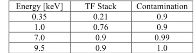
transmission, which implies to use light filter materials and to keep the filter thickness to the minimum value compatible with required attenuation of infrared radiation and mechanical robustness. Molecular contamination sticking on the filters would affects the low energy transmission. The X-ray transmission of the full TF stack, including contribution from contamination, shall be better than the values presented in table 1.
Table 1. X-ray transmission requirements on the TF stack and contamination layer.
Energy [keV] TF Stack Contamination 0.35 0.21 0.9
1.0 0.76 0.9 7.0 0.9 0.99
9.5 0.9 1.0
• IR attenuation. The TES array operates at temperatures ~ 100 mK to keep the thermodynamic noise below the required energy resolution. For this reason, IR radiation from the warm surfaces in the detector field of view (FOV) has to be attenuated to keep the radiation heat load onto the cold stage at least two order of magnitude (TBC) lower than the conductive contribution + dissipated detector bias power, and to keep the photon shot noise contribution to the energy resolution budget < 0.2 eV FWHM (TBC).
• RF attenuation. The TES microcalorimeter detectors and the SQUID based read-out electronics are very sensitive to radio frequency electromagnetic interferences (EMI). For this reason, the TFs have to attenuate the RF EMI from the uplink/downlink X-band telemetry and from onboard electronics. The two thermal shields of the DCS at 200 K and 2 K will be Faraday cages. Each one of the TFs mounted on these shields has to provide an RF attenuation greater than 30 dB (TBC) from 30 MHz to 18 GHz.
• Detector protection from contamination. Molecular contamination from the satellite environment onto the cold detector surfaces could cause loss of efficiency and performance degradation. To prevent a significant deposition of contaminants along the mission lifetime the TFs have to seal the focal plane assembly (FPA) from the external environment. Contaminants deposited on a TF can also cause loss of detection efficiency, for this reason the need to warm-up the outer filters for contamination removal has to be considered in the filter design. The most critical TF for contamination will likely be the outer one, mounted on the 200 K outer shield and exposed to the spacecraft environment. This TF shall be kept at a temperature higher than 320 K (TBC). Furthermore, for the three outer TFs, namely TF200, TF100, and TF30 a heating mechanism shall be implemented to allow decontamination (TBC). The efficiency loss due to contamination deposited on the TF stack during the mission lifetime shall not be larger than 10% at any energy (TBC).
Beside these requirements, the TFs shall withstand a static differential pressure up to 1 mbar (TBC), survive the launch vibration loads of the launcher, and survive a certain number of thermal cycles (TBD).
Given the above requirements and attempting to maximize the low energy response of the X-IFU, entirely defined by the TF stack transmission, we have started an investigation to identify the minimum thickness of polyimide that could provide sufficient strength and reliability, and the minimum thickness of aluminum per filter that could provide sufficient IR reflection[8]. In order to reduce the polyimide thickness, the use of a supporting mesh with small pitch has been considered mandatory, at the price of some efficiency loss at high energy. A polyimide thickness of 45 nm for each filter has been considered feasible by LUXEL Corp., while 20 nm of aluminum has been identified as the minimum thickness to provide adequate IR reflection. Considering that aluminum develops a layer of oxide few nm thick both at the exposed surface and at the interface with polyimide[26], we have chosen a minimum conservative thickness of 30 nm of aluminum deposited on each TF.
3. CURRENT INVESTIGATED DESIGN
According to the above reported requirements and design drivers, and based on the results of preliminary structural analysis under static loads[27], we have identified a TF set to be investigated along the instrument phase-A. Table 2
provides the main characteristics of the investigated set of thermal filters. The meshes designed to improve the mechanical robustness, and thus allow the use of a very thin polyimide film, are currently made of SAE 304 stainless steel (SS) for the four outer filters, and of niobium for the inner filter to not introduce any static magnetic field close to the detector. The SS meshes are plated with 5 µm thick gold to fully absorb Fe fluorescence line emission induced on the meshes by background particles.
Table 2. Main characteristics of the investigated set of thermal filters. Z is the distance from the focal plane. BF is the blocking factor, i.e. the fraction of area covered by the mesh. I.D. is the frame internal diameter.
Name TSHIELD [K] Z [mm] I.D. [mm] MESH
Material Pitch Thickness Bar width BF [mm] [µm] [µm] [%] TF200 200 240 100 SS/Au 5 130 65 3.0 TF100 100 210 88 SS/Au 5 130 65 3.0 TF30 30 180 76 SS/Au 5 130 65 3.0 TF2 2 130 56 SS/Au 2 60 30 4.0 TF0 0.05 15 26 Nb 2 60 30 3.0
Figure 1 left panel provides a view in scale of the investigated TF set. The names of the thermal filters are taken from the temperature of the DCS shields where the filters are mounted. The name TF0 has been assigned for simplicity to the filter operating at 0.05 K.
The three outer TFs will be mounted on the aperture cylinder of the DCS shields, while the two inner and colder filters will be mounted directly on the FPA. The aperture cylinder has been designed in order to minimize the distance of the TF from the focal plane and thus reduce their diameters. The aperture angle defined by the TF diameters is larger than the telescope aperture angle to allow for the four calibration modulated X-ray sources (MXS) to uniformly illuminate the entire focal plane detector. Figure 1 right panel shows a schematic view of the DCS, identifying the location of the TFs mounted on the focal plane and those mounted on the aperture cylinder.
Figure 1. Schematic view of the five thermal filters with distances from the detector and diameter in proper scale (left panel). The right panel shows the thermal filters inside a schematic drawing of the DCS together with the major instrument subsystems.
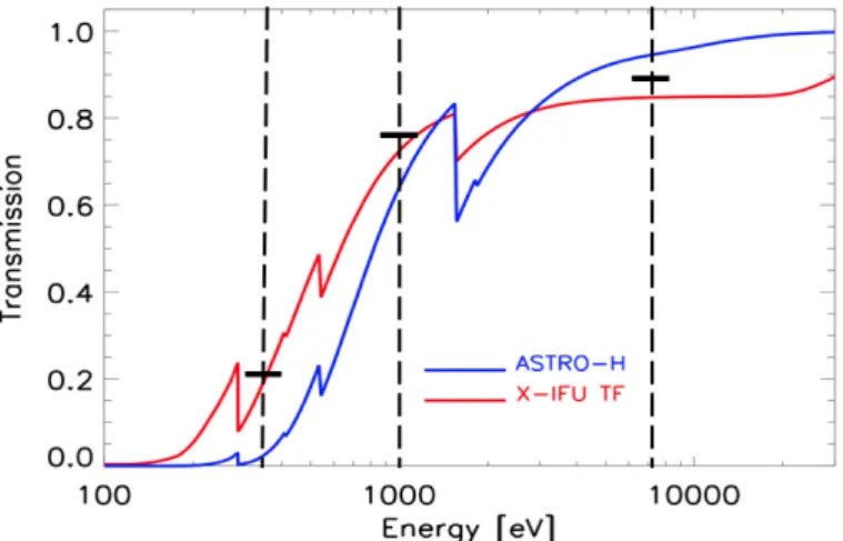
The main driver in the TF design for the X-IFU was to maximize the low energy transmission. Figure 3 shows a comparison between the X-ray transmission of the full stack of five TFs of the X-IFU and the transmission of the full stack of TFs of the Soft X-ray Spectrometer on board Hitomi[19]. Superimposed are the requirements on transmission at 0.35 keV, 1 keV and 7 keV. The current investigated design of the X-IFU TFs provides a huge gain in transmission at low energy, but the use of the thick metal meshes instead of thinner Si meshes determines some loss in efficiency at high energy where the requirements are not satisfied. Our choice of quite thick metal meshes was driven by the need for mechanical strength (the X-IFU filters are much larger than the Hitomi filters), good thermal and electrical conductivity (the meshes have to provide RF attenuation), and good coupling of the thermal expansion coefficient (CTE) with that one of the metal interfaces thus simplifying the mounting of the filter onto the filter frame, frame carrier and AC/FPA.
Figure 2. Modelled X-ray transmission for the currently investigated full set of X-IFU TFs (red line, more transparent in the soft x-rays) vs. the full set of TFs mounted on the Hitomi SXS (blue line). The horizontal marks at 0.35 keV, 1 keV, and 7 keV are the scientific requirements for the X-IFU stack of TFs.
4. CHARACTERIZATION TESTS SUPPORTING THE DESIGN
In order to support the design consolidation of the X-IFU TFs, and to start increasing the TRL of the proposed technology, we have procured/manufactured different test samples along the phase-A. Such samples can be divided in three main sets (samples numbering is chronological with first samples procured in October 2015, and last ones in March 2018): 1) small size witness samples for optical properties characterization and surface analysis mounted on standard TF111 LUXEL frames with 15 mm inner diameter; 2) large size samples with representative meshes and thick polypropylene films replacing the thin polyimide to test the mechanical properties of the meshes; 3) medium
size samples with representative meshes (including the gold plating) and representative thin polyimide films coated
with aluminum for mechanical and environmental tests of the thin membrane mounted on meshes.
1. Small size witness samples (I.D. = 15 mm)
- sample #1: 45 nm LUXFilm® polyimide/30 nm Al film, meshless; - sample #2: 45 nm LUXFilm® polyimide film, meshless;
- sample #8: 20 nm Al/45nm LUXFilm® polyimide/20 nm Al film, meshless; - sample #9: 20 nm Al/45nm LUXFilm® polyimide film, meshless;
- sample #10: 15 nm Al/45nm LUXFilm® polyimide/15 nm Al film, meshless; - sample #11: 15 nm Al/45nm LUXFilm® polyimide film, meshless.
2. Large size samples
- sample #3: 700 nm polypropylene/40 nm Ti, I.D. = 100 mm, SS coarse mesh; - sample #4: 700 nm polypropylene/40 nm Ti, I.D. = 56 mm, SS fine mesh; - sample #7: 700 nm polypropylene/40 nm Ti, I.D. = 56 mm, Nb fine mesh. 3. Medium size samples:
- sample #5: 45 nm LUXFilm® polyimide/30 nm Al film, I.D. = 30 mm, Au plated SS coarse mesh; - sample #6: 45 nm LUXFilm® polyimide/30 nm Al film, I.D. = 30 mm, Au plated SS fine mesh.
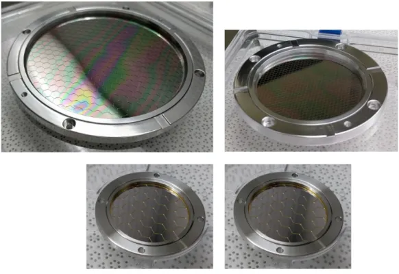
The coarse and fine meshes, with pitch of 5 mm and 2 mm respectively, are better described in Table 2. Figure 3 shows pictures of two large size samples, namely sample #3 (top left) and #4 (top right), and two medium size samples, namely sample #5 (bottom left) and #6 (bottom right).
Figure 3. Pictures of the large size samples #3 (top left) and #4 (top right), and of the medium size samples #5 (bottom left) and #6 (bottom right).
Preliminary results have been reported elsewhere on optical characterization and surface analysis investigation[10][26] , vibration tests performed on large size samples #3 and #4 at the Centre Spatial de Liege in March 2017[27], thermo-vacuum tests performed on the same samples at INAF-OAPA in Palermo[27], and high resolution X-ray spectroscopy measurements[28]. Here we report some results from further optical characterization measurements and mechanical tests performed on new filter samples.
4.1 Transmission measurements and modelling
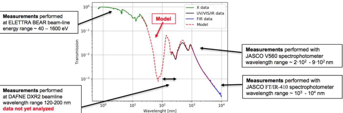
Figure 4 shows a comparison between UV/Vis/IR transmission modelling and measurements performed with different instruments on a sample of 45 nm LUXFilm® polyimide/30 nm Al film, meshless. The calculations are derived using the matrix formulation of the electromagnetic field boundary conditions[29], with the refractive index of aluminum and polyimide derived from[30][31][32][33][34].
The best fit modelling is consistent with a total amount of 7 nm of aluminum oxide, which suggests that the same amount of oxide forms at the interface with the polyimide and on the open surface as measured with XPS at the BACH beamline of the ELETTRA Synchrotron (Basovizza, Italy)[26]. The UV modelling also fits well with the soft X-ray measurements performed at the BEAR beamline of ELETTRA.
Figure 4. Modelled UV/Vis/IR transmission (red dashed line) for a filter sample consisting of 45 nm LUXFilm® polyimide/30 nm Al film, meshless, compared with measurements performed with different instruments.
4.2 Vibration tests
A new vibration test campaign was performed in November 2017 at the Max-Planck-Institut fuer Extraterrestrische Physik (MPE). Sine, random, and shock vibration tests, carried out using an UD T-1000 shaker, were aimed at testing the performance of the thin polyimide/Al film supported by representative fine and coarse Au plated SS meshes (medium size samples #5, #6), and to test the performance of the Nb fine mesh (large size sample #7). The adopted reference sine and random vibration test levels, derived from the Ariane 5 launcher manual[35], are reported in Tables 3. Increasing load levels were applied to the filters, while approaching the reference level, with shorter duration with respect to the reference level in order to reduce the risk of fatigue failure. The reference level and higher levels were maintained for the full reference duration.
Table 3. Sine and random vibration load reference levels.
Sine (25.0 g 0-peak, sweep rate=2 Oct/min) Random (16.9 g RMS, duration=150 s)
Frequency range (Hz) Level
5.0 – 23.0 11.7 mm (0-peak) 23.0 – 100.0 25.0 g (0-peak) Frequency range (Hz) PSD 20.0 – 100.0 +3.00 dB/oct 100.0 – 300.0 0.5 g2/Hz 300.0 – 2000.0 -5.00 dB/oct
All tested X-IFU filter samples survived in-plane reference vibration levels and out-of-plane vibration levels increased by +10g 0-peak sine load and + 3dB random load with respect to the reference levels. Filters have also survived out-of-plane shock reference tests according to the load level specified in Table 4.
Table 4. Shock test reference level (axial), Q = 10
Frequency (Hz) SRS(g)
100 20
1000 400
3000 400
MPE. Vibration tests were performed keeping the filters in vacuum during the vibrations, to mimic the launch condition and to reduce potential damages from flying particles.
Figure 5. X-IFU filter samples #5, #6, and #7 mounted on the mechanical interface attached to the model UD T-1000 shaker at MPE during vibration tests performed in November 2017.
4.3 Acoustic tests
Despite the current baseline is to launch the X-IFU DCS in vacuum, thus without acoustic load on the thermal filters, launching in vacuum has some drawbacks such as a larger mass allocation or the lack of thermal conductance to dissipate the heating caused on suspension Kevlar wires by the launch vibrations. For these reasons, the option to launch the DCS in atmospheric pressure or moderate residual pressure is under evaluation as a back-up solution.
In order to investigate whether the TFs can survive launch without vacuum, a preliminary acoustic test has been conducted in the reverberation chamber of the Mechanics and Vibro-acoustic Department of the AGH University in Krakow on April 2018. Five filter test samples from #3 to #7 were mounted inside a vacuum tight box. Acoustic tests were run at different residual pressures inside the box, namely: 1 mbar, 10 mbar, 100 mbar, and 1000 mbar. The acoustic noise reference spectrum adopted for the test campaign has been derived from the Ariane 5 launcher manual[35], and is reported in Table 5. The last row provides the overall acoustic sound pressure level (OASPL) integrated in the frequency band 20-2028 Hz.
Table 5. Acoustic Noise Reference Spectrum.
Octave Center Frequency [Hz]
Sound Pressure Level [dB] 31.5 128 63 131 125 136 250 133 500 129 1000 123 2000 116 OASPL (20-2828 Hz) 139.5
Acoustic tests were performed in wide band with a spectrum as close as possible to the reference one. Increasing load levels were applied starting at a sound pressure level (SPL) of 110 dB at the peak of the spectrum (approx. 125 Hz) and raising the level with 6 dB steps up to 128 dB. At higher levels, up to the maximum, the level was increased at 3 dB steps. Every test lasted 30 s up to the highest level, maintained for 120 s.
Figure 6 left panel shows the vacuum tight box placed inside the reverberation chamber at AGH. The right panel shows the acoustic load spectrum measured in the reverberation chamber (red) compared with the reference level (orange), and that one measured inside the vacuum tight box kept at atmospheric pressure (blue). The sound pressure level at frequency higher than ~125 Hz is significantly dumped by the box, while at low frequency the box transmits the sound spectrum nearly unchanged.
Figure 6. Vacuum tight box used to test the X-IFU filter samples #3 to #7 mounted inside the reverberation chamber at AGH University in Krakow (left panel). The right panel shows the measured sound spectrum inside the reverberation chamber (red line) compared with the reference spectrum (orange line), and the spectrum measured inside the box kept at atmospheric pressure (blue line).
All X-IFU filter samples survived the acoustic load up to the Ariane 5 reference level (137 dB @ 125 Hz) both in moderate vacuum (1, 10, 100 mbar) and at atmospheric pressure (1000 mbar). Despite these encouraging results, a more significant test should be performed keeping the filters in an acoustic environment representative of the actual mounting inside the DCS or with a simulated acoustic spectrum derived from the knowledge of the DCS transfer function. If new tests will confirm that launching the DCS in atmospheric pressure or partial pressure is acceptable and this option becomes the new baseline, proper care will need to be put in the design of the evacuation paths, to prevent differential pressures to build up across the thin fragile filters during the few tens of seconds needed for the launcher cargo to evacuate while the rocket exits the Earth atmosphere.
4.4 RF attenuation tests
As previously mentioned, the TFs have also to protect the sensitive TES array and SQUID based read-out electronics from the radio frequency (RF) originating from the spacecraft antenna and from on-board electronics. In the current DCS design, the two thermal shields at 2 K and 200 K are designed as Faraday cages to provide electromagnetic shielding. Each of the TFs mounted on these shields, namely TF2 and TF200, has to ensure 30 dB attenuation in the range 30 MHz-18 GHz[25]. In order to prove that our filter design can provide the required RF attenuation, we have set-up an experimental bench at the XACT facility of INAF-OAPA[36] for the low frequency range (< 3 GHz) and at UNIPA for the high frequency range (3-20 GHz). Figure 7 shows the two reverberation chambers designed and built to perform measurements at low frequencies (diameter 250 mm) and at high frequencies (diameter 100 mm), respectively.
Figure 7. Reverberation chambers (100 mm and 250 mm diameters) designed and built to perform RF attenuation measurements on X-IFU thermal filter samples.
A detailed description of the apparatus, adopted experimental approach and results is presented in[23]. The experimental campaign has proven that a thin film of aluminum 30 nm thick is capable to provide at least 30 dB attenuation at frequencies higher than approximately 6 GHz. On the other hand, a metal mesh with a pitch of 4 mm is capable to provide the requested attenuation at lower frequencies. The combination of a 30 nm Al film with a such a mesh is compliant with the requirements in the investigated frequency range 2-20 GHz. The experimental activity will proceed with RF attenuation measurement of meshes with different geometrical parameters (pitch and bar width), in order to identify the proper geometry of the optimized meshes for TF2 and TF200. The overall attenuation of the full set of TFs strongly depends on the design of the aperture cylinder and focal plane assembly (e.g. geometry, surface treatment, etc.), for this reason, in order to estimate the total RF shielding efficiency we will perform RF modelling and measurements on a simple mock-up of the AC and FPA shields with representative TFs in place.
5. TRADE-OFF ANALYSIS AND DESIGN CONSOLIDATION
According to simulations and measurements performed so far, the current investigated design of the X-IFU TFs, described in section 3, are compliant with the functional requirements. However, as shown in Figure 2, the use of thick metal meshes to provide mechanical robustness and RF attenuation at low frequencies (< 6 GHz) causes a reduction of the overall X-ray transmission such that the scientific requirements at E > 1 keV are not satisfied. In this section, we discuss how we plan to improve the TFs design to fully meet the scientific requirements.
5.1 Can we remove one of the TFs in the stack?
The first attempt was to evaluate whether one of the five filters in the stack could be removed without significant impact on the radiative heat load onto the detector. In order to verify this option, we have performed a thermal modelling of the TFs stack[22] to derive the temperature profile of each filter in the various configurations. For each configuration, we have then calculated the photon shot noise contribution (FWHM) to the energy resolution budget, according to the formulation presented in [9] with the following updated assumptions:
1. both the aluminum and polyimide side of the filters have an emissivity of 0.05;
2. filters are tilted by 2°, in alternate directions, with respect to the horizontal plane, to reduce multiple reflections; 3. the adopted microcalorimeter detection time needed for optimal filtering is 7.5 ms (TBC);
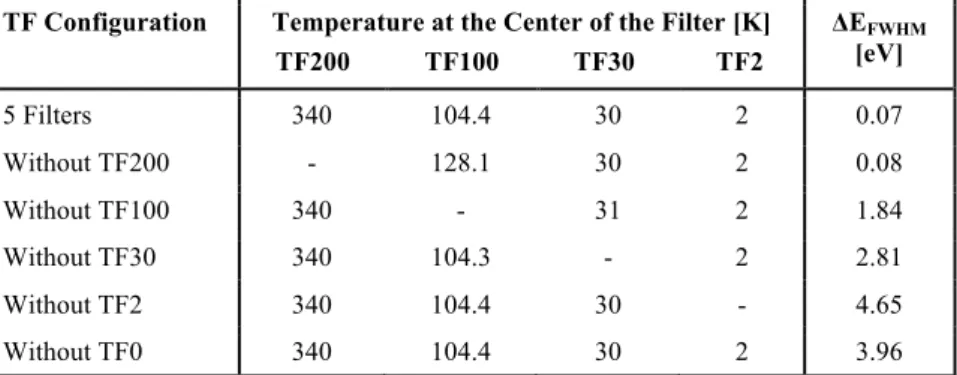
Table 5 shows the average effective temperature of each filter as derived from the thermal modelling and the contribution to the photon shot noise for each configuration. Notice that TF200 is much warmer than its shield temperature since in order to minimize the molecular contamination it is required that it operates at temperatures higher than 320 K.
The removal or break of any of the inner four filters has a significant impact on the detector energy resolution. The removal of TF200 is not viable since it is the main molecular contamination shield.
Table 6. Effective temperature of each TF in the various investigated configurations and associated photon shot noise contribution (FWHM) to the energy resolution budget.
TF Configuration Temperature at the Center of the Filter [K] TF200 TF100 TF30 TF2 ΔEFWHM [eV] 5 Filters 340 104.4 30 2 0.07 Without TF200 - 128.1 30 2 0.08 Without TF100 340 - 31 2 1.84 Without TF30 340 104.3 - 2 2.81 Without TF2 340 104.4 30 - 4.65 Without TF0 340 104.4 30 2 3.96
5.2 Can we increase the mesh cell size?
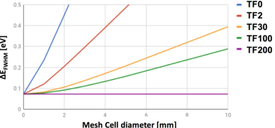
As a second option, we evaluated whether it is possible to increase the mesh pitch to reduce the blocking factor, in particular on those filters where there is no requirement on RF attenuation. Thin unsupported membranes when subject to a local damage or hole usually fully break. The use of supporting meshes protects the filters from full breakage limiting the local damage to within one cell. We have thus evaluated what is the impact onto the photon shot noise caused by an open cell in each one of the five TFs as a function of the cell diameter (Figure 8). The use of a mesh with a pitch size < 2 mm is necessary on TF0, and < 3 mm on TF2 to reduce the effect of local damages on the detector energy resolution. TF30, TF100 and TF200 can tolerate larger holes and thus meshes with a pitch size ~ 5 mm can be used.
Figure 8. Photon shot noise as a function of the diameter of an open cell on each filter. The curves are from top to bottom relative to the filters TF0 (blue), TF2 (red), TF30 (yellow), TF100 (green), and TF200 (cian).
5.3 Frame and mesh design optimization
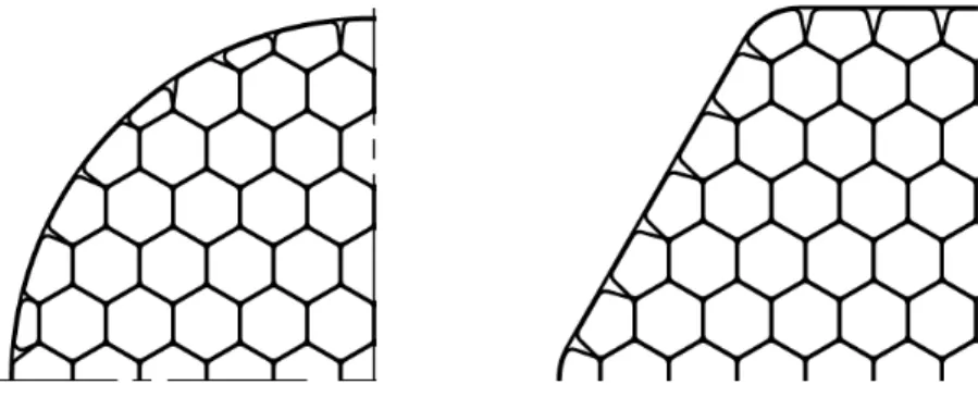
In order to reduce the blocking factor of the TFs to meet the X-ray transmission requirements at E > 1 keV, based on the encouraging results from vibration and acoustic tests performed on partially representative filter samples, we have started to review the mechanical design of the filter frames and the mesh, trying to minimize the stress concentration and thus being able to reduce the mesh bar width and thickness. Figure 9 shows a comparison between the current investigated circular frame design (left) and an alternative option under investigation (right) with hexagonal shape matching the shape of the detector array.
Figure 9. Comparison between the current investigated circular frame design (left) and an alternative option under investigation (right) with hexagonal shape matching the shape of the detector array. Both configurations have the usual approach with the mesh (red) and the membrane glued together in between an inner and an outer frame (green).
As shown in Figure 10, the hexagonal shape allows to have a uniform attachment of the mesh wires on the frame and thus a more uniform distribution of the stress with respect to the circular frame. The hexagonal frame shape, according to structural modelling, can provide a gain of a factor between 1.5 and 2 in maximum static pressure before plastic deformation of the mesh.
Figure 10. Mesh wire attachment to the frame in the circular (left) and hexagonal (right) frame designs.
Table 7 reports the main parameters of the optimized TFs design. Figure 11 shows that this TFs configuration meets the X-ray transmission requirements.
Table 7. Main characteristics of the set of thermal filters with optimized design.
Name TSHIELD
[K] [mm] Z [mm] I.D.
MESH
Material Pitch Thick. Bar width BF [mm] [µm] [µm] [%] TF200 200 240 100 SS/Ag 5 80 40 2.4 TF100 100 210 88 SS/Au 5 80 40 2.0 TF30 30 180 76 SS/Au 5 80 40 2.0 TF2 2 130 56 SS/Au 2 40 20 2.0 TF0 0.05 15 26 Nb 2 60 30 3.0
Figure 11. Modelled X-ray transmission for the full set of optimized design X-IFU TFs (red dashed line) vs. the full set of currently investigated design X-IFU TFs (red solid line) and the full set of TFs used on Hitomi SXS (blue line). The horizontal marks at 0.35 keV, 1 keV, and 7 keV are the requirements.
6. SUMMARY AND CONCLUSIONS
In this paper, we have reviewed the development status of the thermal filters that will be mounted on the focal plane assembly and aperture cylinder of the Athena X-IFU detector cooling system to protect the sensitive microcalorimeter array from IR radiative load, RF EMI, and molecular contamination.
The currently investigated design consists of a stack of five filters mounted on the opening windows of the thermal shields operating at 50 mK, 2 K, 30 K, 100 K, and 200 K, respectively. In order to maximize the low energy response, each filter will consist of 45 nm thick polyimide film coated with 30 nm of aluminum, glued and electrically connected to a thick metal mesh which provides mechanical support, thermal conductance, and RF attenuation at low frequencies (< 6 GHz).
A few filter samples, partially representative of the current design, have been procured to characterize the material properties, demonstrate the capability of such filters to withstand launch stresses, and start increasing the TRL.
The experimental results and simulations performed so far, show that the currently investigated TFs satisfy most of the requirements, in particular:
• the photon shot noise contribution to the energy resolution budget is ΔEFWHM < 0.2 eV with all 5 filters in place
and undamaged;
• TF2 and TF200 can provide each an RF attenuation > 30 dB in the frequency range 2-20 GHz. • the TF samples survived Ariane V launch vibration and preliminary acoustic tests.
The use of thick metal meshes, however, affects the filter transmission which is not fully compliant with the requirements at E > 1 keV. Based on the very encouraging results from environmental tests and structural analysis, an optimization of the frame and mesh design is ongoing to reduce the mesh blocking factor and fully meet the X-ray transmission requirements. A new set of optimized filter samples will be procured and tested under vibration and acoustic loads to consolidate the design before the end of Phase-A.
ACKOWLEDGMENTS
The research leading to these results has received funding from ASI (Italian Space Agency) under the contract n. 2015-046-R.0, from the European Union’s Horizon 2020 Program under the AHEAD project (grant agreement n. 654215), and from ESA (European Space Agency) under the contract n. 4000120250/17/NL/BJ. We acknowledge fruitful discussions and support by LUXEL corp.
REFERENCES
[1] Barcons, X., et al., “Athena: the X-ray observatory to study the hot and energetic Universe”, Journal of Physics Conference Series, Volume 610, Issue 1, (2015). doi:10.1088/1742-6596/610/1/012008
[2] Nandra, K., et al., “The Hot and Energetic Universe: A White Paper presenting the science theme motivating the Athena+ mission," e-print arXiv:1306.2307 (2013).
[3] Willingale, R., Pareschi, G., Christensen, F., and den Herder, J.-W., "The Hot and Energetic Universe: The Optical Design of the Athena+ Mirror", e-print arXiv:1307.1709W (2013).
[4] Bavdaz, M., et al., “The ATHENA telescope and optics status”, Proc. SPIE, 10399, 103990B (2017).
[5] Barret, D., et al., “The Athena X-ray Integral Field Unit (X-IFU),” Proc. SPIE, 9905, 99052F (2016). doi: 10.1117/12.223243
[6] Pajot, F., et al., “The Athena X-ray Integral Field Unit (X-IFU)”, JLTP, published online first (2018). doi: 10.1007/s10909-018-1904-5
[7] Rau, A., et al., "The Hot and Energetic Universe: The Wide Field Imager (WFI) for Athena+", e-print arXiv:1308.6785 (2013).
[8] Meidinger, N., Barbera, M., Emberger, V., Fürmetz, M., Manhart, M., Müller-Seidlitz, J., Nandra, K., Plattner, M., Rau, A., Treberspurg, W., “The Wide Field Imager instrument for Athena,” Proc. SPIE, 10397, 103970V (2017). doi: 10.1117/12.2271844.
[9] Barbera, M., Collura, A., Gatti, F., Lo Cicero, U., Macculi, C., Piro, L., Renotte, E., Sciortino, S., “Baseline design of the thermal blocking filters for the X-IFU detector on board ATHENA”, Proc. SPIE, 9144, 91445U (2014). doi: 10.1117/12.2057403
[10] Barbera, M., Argan, A., Bozzo, E., Branduardi-Raymont, G., Ciaravella, A., Collura, A., Cuttaia, F., Gatti, F., Jimenez Escobar, A., Lo Cicero, U., Lotti, S., Macculi, C., Mineo, T., Nuzzo, F., Paltani, S., Parodi, G., Piro, L., Rauw, G., Sciortino, L., Sciortino, S., Villa, F., “Thermal Filters for the ATHENA X-IFU: Ongoing Activities Toward the Conceptual Design”, J. Low Temp. Phys., 184, 706–711 (2016). doi: 10.1007/s10909-016-1501-4. [11] Bozzo, E., Barbera, M., Genolet, L., Paltani, S., Sordet, M., Branduardi Raymont, G., Rauw, G., Sciortino, S.,
Barret, D., Den Herder, J., “The filter wheel and filters development for the X-IFU instruments onboard Athena”, Proc. SPIE, 9905, 990561 (2016). doi: 10.1117/12.2232328
[12] Barbera, M., Austin, K., Collura, A., Flanagan, K., Jelinsky, R., Murray, S., Serio, S., Zombeck, M.V., "Development of the UV/ion shields for the Advanced X-ray Astrophysics Facility high-resolution camera (AXAF HRC)", Proc. SPIE, 2280, 214-228 (1994). doi: 10.1117/12.186815
[13] Meehan, R., Murray, S., Zombeck, M.V., Kraft, P., Kobayashi, K., Chappell, H., Kenter, A., Barbera, M., Collura, A., Serio, S., "Calibration of the UV/ion shields for the AXAF High-Resolution Camera", Proc. SPIE, 3114, 74-100 (1997). doi: 10.1117/12.283790
[14] Villa, G.E., Barbera, M., Collura, A., La Palombara, N., Musso, C., Serio, S., Stillwell, R., Tognon, P., Turner, D.C., “The optical/UV filters for the EPIC experiment”, IEEE Transactions on Nuclear Science, 45, 921-926 (1998). doi: 10.1109/NSSMIC.1997.672658
[15] Barbera, M., Agnello, S., Buscarino, G., Collura, A., Gastaldello, F., La Palombara, N., Lo Cicero, U., Tiengo, A., Sciortino, L., Varisco, S., Venezia, A.M., "Status of the EPIC thin and medium filters on-board XMM-Newton after more than 10 years of operation: 1) laboratory measurements on back-up filters", Proc. SPIE, 8859, 885914 (2013). doi: 10.1117/12.2030896
[16] Gastaldello, F., Barbera, M., Collura, A., La Palombara, N., Lo Cicero, U., Sartore, N., Tiengo, A., Varisco, S., "Status of the EPIC thin and medium filters on-board XMM-Newton after more than 10 years of operation: 2) analysis of in-flight data", Proc. SPIE, 8859, 885915 (2013). doi: 10.1117/12.2030897
[17] McCammon, D., et al., “The X-ray Quantum Calorimeter Sounding Rocket Experiment: Improvements for the Next Flight”, JLTP 151(3–4), 715–720 (2008). doi: 10.1007/s10909-008-9734-5
[18] Audley, M.D., et al., "ASTRO-E/XRS blocking-filter calibration", Proc. SPIE 3765, 751–761 (1999). doi: 10.1117/12.366558
[19] de Vries, C.P., et al., "Filters and calibration sources for the soft x-ray spectrometer (SXS) instrument on ASTRO-H", Proc. SPIE, 7732, 773213 (2010). doi: 10.1117/12.855880
[20] Kilbourne, C.A., et al., “The design, implementation, and performance of the Astro-H SXS aperture assembly and blocking filters”, Proc. SPIE 9905, 99053Q (2016). doi: 10.1117/12.2232240
[21] ESA report, “Technology Readiness Levels Handbook for Space Applications”, TEC-SHS/5551/MG/ap (2008). [22] Sciortino, L., et al., “Thermal Modeling of the ATHENA X-IFU Filters”, Proc. SPIE, 10699, in press. (2018). [23] Lo Cicero, U., et al., “Radio Frequency shielding of thin aluminized plastic filters investigated for the ATHENA
X-IFU detector”, Proc. SPIE, 10699, in press. (2018).
[24] Parodi, G., et al., “Structural modeling and mechanical tests supporting the design of the ATHENA X-IFU thermal filters and WFI optical blocking filter”, Proc. SPIE, 10699, in press. (2018).
[25] CNES report, “X-IFU Optical Thermal Blocking Filter Requirements Document”, XIFU-RD-10000-00347 - draft (2018).
[26] Sciortino, L., Lo Cicero, U., Magnano, E., Píš, I. and Barbera, M. “Surface investigation and aluminum oxide estimation on test filters for the ATHENA X-IFU and WFI detectors”, Proc. SPIE, 9905, 990566 (2016). doi: 10.1117/12.2232376
[27] Barbera, M., et al. “Preliminary Mechanical Characterization of Thermal Filters for the X-IFU Instrument on Athena”, JLTP published on-line first (2018). doi: 10.1007/s10909-018-1942-z
[28] Sciortino, L., et al., “A temperature dependent X-ray absorption characterization of test filters for the ATHENA mission X-IFU instrument”, JLTP published on-line first (2018). doi: 10.1007/s10909-018-2015-z
[29] Born M. and Wolf E., "Principles of Optics", 6th edition (1997), Cambridge University Press (UK), ISBN 0521639212.
[30] Smith, D.Y., "The optical properties of metallic aluminum", in Handbook of Optical Constants of Solids, p. 369-406 (1985), Edited by Edward D. Palik, ISBN: 978-0-12-544415-6
[31] Rakic., A.D., "Algorithm for the determination of intrinsic optical constants of metal films: application to aluminum", Appl. Opt. 34, 4755-4767 (1995). doi: 10.1364/AO.34.004755
[32] Hagemann, H.J., et al., "Optical constants from the far infrared to the x-ray region: Mg, Al, Cu, Ag, Au, Bi, C, and Al2O3", J. Opt. Soc. Am. 65, 742-744 (1975).
[33] Henke, B.L., et al.” X-ray interactions: photoabsorption, scattering, transmission, and reflection at E=50-30000 eV, Z=1-92, Atomic Data and Nuclear Data Tables, 54 181-342 (1993).
[34] Cavadi, A., Artale, A., Barbera, M., Collura, A., Powell, R., Varisco, S., "Measurement of optical constants n and k of lexan and polyimide", Proc. SPIE, 3765, 805-815 (1999). doi: 10.1117/12.366568
[35] ARIANESPACE, “Ariane 5 User’s Manual, Issue 5, Revision 2” (2016).
[36] Barbera, M., Candia, R., Collura, A., Di Cicca, G., Pelliciari, C., Sciortino, S., Varisco, S., “The Palermo XACT facility: a new 35 m long soft x-ray beam-line for the development and calibration of next-generation x-ray observatories”, Proc. SPIE, 6266, 62663F (2006). doi: 10.1117/12.673004