O
pen
A
rchive
T
OULOUSE
A
rchive
O
uverte (
OATAO
)
OATAO is an open access repository that collects the work of Toulouse researchers and
makes it freely available over the web where possible.
This is an author-deposited version published in :
http://oatao.univ-toulouse.fr/
Eprints ID : 16043
To link to this article : DOI : 10.1063/1.3503925
URL :
http://dx.doi.org/10.1063/1.3503925
To cite this version : Chauvet, Fabien and Duru, Paul and Prat, Marc
Depinning of evaporating liquid films in square capillary tubes:
Influence of corners’ roundedness. (2010) Physics of Fluids, vol. 22
(n° 11). pp. 112113-1-112113-14. ISSN 1070-6631
Any correspondence concerning this service should be sent to the repository
administrator:
[email protected]
Depinning of evaporating liquid films in square capillary tubes:
Influence of corners’ roundedness
F. Chauvet, P. Duru,a!and M. Prat
Université de Toulouse, INPT, UPS, IMFT (Institut de Mécanique des Fluides de Toulouse), Allée Camille Soula, F-31400 Toulouse, France and CNRS, IMFT, F-31400 Toulouse, France
In this paper, evaporation of a volatile, perfectly wetting liquid confined in an initially filled capillary tube of square internal cross section is studied, when conditions are such that liquid films develop along the tube internal corners under the effect of capillary forces, as the bulk meniscus recedes inside the tube. More precisely, the emphasis is on the moment when the liquid film tips depin from the tube top once they have reached a critical length, a phenomenon observed in experiments. A model taking into account liquid corner flow and phase change at the film tip is proposed in order to predict the critical film length at depinning. The model is found to be in good agreement with experimental data and highlights that the critical film length depends strongly on the degree of roundedness of the tube internal corners. Thus, it is crucial to take into account this purely geometrical factor when modeling evaporation in polygonal capillary tubes or, more generally,
corner flows in a rounded wedge. doi:10.1063/1.3503925
I. INTRODUCTION
Evaporation from liquid menisci in confined environ-ment is of importance in many applications, such as cooling technologies1or drying of porous media.2Understanding the fundamental processes involved in these applications is es-sential and has motivated many studies ssee, for example, Ref.3 and references thereind. In this context, the
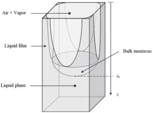
consider-ation of evaporconsider-ation in a single tube or microchannel is an important step for the understanding of more complex sys-tems, such as, for example, networks of interconnected cap-illaries, which are common in microfluidic applications4and which are also frequently used as conceptual models of po-rous media.2Our motivation for the consideration of such an elementary system originates more specifically from experi-mental results in etched networks of channels of rectangular cross section, showing that evaporation was much faster than initially expected.5The effect was conjectured to be due to the effects of liquid films trapped by capillarity in the corners of the channels invaded by the gas phasessee Fig.1d. Since
then, the consideration of these corner films in relation with drying problems has motivated several modeling and nu-merical studies6,7 and it is now widely admitted that these films play a major role not only in etched networks, but also in most porous media. However, this is only very recently that careful experimental studies were developed with the twofold objective of gaining a better understanding of evapo-ration in the presence of corner films and developing quan-titative predictive models.8,9The present paper notably high-lights the influence of corner roundedness. As we shall see, the tube evaporation kinetics is greatly affected by the tube degree of roundedness. Hence, a somewhat tiny geometrical detail has a great influence on evaporation. This has
impor-tant implications for the drying of porous media since the study clearly suggests that evaporation in porous media should depend on tiny details of the pore space geometry and therefore contributes to explaining why quantitatively pre-dicting the evaporation rate of porous media remains a chal-lenging problem. Also, it is interesting to notice that the mass transfer driven evaporation from a circular tube is well un-derstood since the 19th century10 and is a classic textbook problem, usually referred to as the “Stefan tube problem.”11 The situation is completely different in tubes of polygonal cross section. The presence of corners and associated corner liquid films leads to much greater evaporation rates9 but makes the analysis significantly more involved. The evapo-ration enhancement is explained by the corner liquid films. As sketched in Fig.1, “thick” and elongated liquid films are trapped by capillary forces along the tube’s four internal cor-ners in the square tube considered in the present study, if the liquid wetting contact angleuis inferior to a critical contact angleuc= 45°.
12,13
These corner films provide transport paths for the liquid between the receding bulk meniscus and the entrance of the tube. The liquid is transported within the films under the action of the pressure gradient induced by the meniscus curvature variation along the films, up to the tube’s opened end, where it evaporates. Viscous resistance to the corner flow and gravity swhen the tube is held verticallyd tend to oppose to the capillary pumping. The relative impor-tance of these three effects can be quantified by introducing two dimensionless numbers: the capillary sCa=viscous effects/capillary effectsd and the Bond numbers sBo = gravity effects/capillary effectsd. When there are no corner filmssu$ucd, the phase change takes place at the bulk me-niscus and vapor is transported by molecular diffusion up to the tube top as in the Stefan tube problemstube of circular cross sectiond.
Corner liquid films are, of course, important not only for mass transfer driven evaporation problem. Situations similar
adAuthor to whom correspondence should be addressed. Telephone: 133-534-32-28-77. Fax: 133-534-32-28-99. Electronic mail: [email protected].
to the one described above, where a liquid confined in a corner or wedge flows under the action of capillary forces, are encountered in various research fields and have been dis-cussed widely in the literature. For instance, the imbibition of a wetting liquid along a corner can be related to oil recov-ery problems in a porous medium.14,15 Corner flows are also relevant in many applications involving microsystems, such as microheat pipes. In a microheat pipe, a volatile liquid is transported by capillary pumping in wedges to some hot re-gions of the device where it vaporizes. In contrast with the situation considered in the present paper, evaporation is driven by heat transfer in this case. Numerous studies fo-cused on the length of the liquid-wetted region, an important parameter to model to quantify the microheat pipe efficiency and cooling capabilities1,16 and on the Marangoni flows re-sulting from the temperature gradients, which can oppose the capillary-induced motion, leading to stationary interface shape.17–19The modeling of corner flows in a wedge usually relies on the assumption of a perfectly sharp corner in the wedge. If this is certainly relevant when dealing with micro-systems made using Silicium-etching based techniques, which lead to sharp angles down to submicron scale, this is not the case when working with corners fabricated from solid materials by other techniques, such as machining or extru-sion sas is the case for glass capillary tubes of polygonal cross sectiond. However, we are aware of only a few works that tried to incorporate the corner or wedge degree of round-edness in the description of the abovementioned systems. Several works focused on the variation of the viscous resis-tance for corner flow as a function of the wedge degree of roundedness.14,20,21All these works show that the resistance is increasing with the degree of roundedness and can then be much larger than that for the sharp corner case. Dong and Chatzis15 have then shown that the spreading dynamics of a wetting droplet in a rounded wedge is going to be slowed down compared to the sharp corner case. In Chen et al.,21the authors mention that the tube roundedness is also going to limit the drop final extension in the wedge, in the case of a perfectly wetting fluid, which would spread to infinity in a sharp wedge in the absence of gravity. It can also be men-tioned that in a static case, in the absence of gravity, it has been shown by Concus and Finn22 that the classical
condi-tions established in previous works12,13 for corners films to develop—u,uc=p/2 −a, where a is the corner half-angle—is modified when the corner is rounded. For a given a, when the degree of roundedness is nonzero, smaller criti-cal contact angles have to be considered, compared to the perfect corner case, for corners films to be present.
As mentioned before, the main scope of this paper is to study how evaporation in a square capillary tube is affected by the tube degree of roundedness. We deal with slow evapo-ration in a stagnant dry air, under atmospheric pressure, and at ambient temperature. Under these conditions, the phase change is limited by mass transfer and the system is sup-posed to be isothermal. Experiments using an infrared ther-mography technique have confirmed the fact that the phase change takes place at the top of the square capillary tube.9 However, this is true only for a first stage of the experiment. Indeed, it was shown by infrared thermography9 and by charge-coupled device sCCDd camera visualizations23 that the corner films depin from the tube top after a while and then recede inside the tube, a phenomenon not predicted by earlier modeling attempts.9More precisely, the drying kinet-ics of a square tube was described in Chauvet et al.8 and shown to be characterized by three main periods: a first pe-riod where the films remain attached to the tube entrance and slowly get thinner in the tube entrance region sas well as within the tubed, and two periods where the films’ tip is located inside the tube. The evaporation flux is much higher during the first period, which essentially depends on the ex-ternal mass transfer sas opposed to the third one, which is dominated by the transfers inside the tube and the second one, which depends on both the external and internal trans-fersd. The event marking the end of the first period is the films’ depinning from the tube entrance. Since the first pe-riod is the high evaporation flux pepe-riod, it is particularly important to predict its duration and therefore the films’ de-pinning. Consequently, the main goal of the present paper is to predict the depinning through an improved modeling of the films’ thickness evolution during the first period and at depinning, notably by taking into account the effect of tube roundedness and then to compare the model predictions to some experimental results.
The paper is organized as follows. First, we rapidly de-scribe the experimental setup and techniques used. Then, we first show how the internal corner degree of roundedness is controlling the maximal extension of hydrostatic, nonvolatile corner liquid films before turning to the more involved case of an evaporating fluid in Sec. IV. The predictions of the model are then compared to experimental data in Sec. V. Conclusions are drawn in Sec. VI.
II. EXPERIMENTAL SETUP
The experimental setup consists of a capillary tube, held vertically and glued at one of its ends by an epoxy resin directly to a syringe tip, the other end being opened and placed in stagnant dry air. The tube filling is controlled by a precision syringe pumpsPHD 2000, Harvard Apparatusd.
Two types of capillary glass tubes were used in the present work. First, a 10 cm long square capillary tubes
FIG. 1. Sketch of the thick liquid films in a capillary tube of square cross section. The bulk meniscus position is denoted as z0.
made of borosilicate glass and supplied by Vitrocom. The internal side length and wall thickness of the tubes are given in TableI. As can be noticed by imaging tubes’ cross sections with an optical microscope, the tubes’ internal corners are not sharp. The degree of roundedness r0, as defined in Fig. 2sad, is estimated by fitting the internal corners’ shapes by quarters of circular arcs for several tube cross sectionsfsee Fig.2sbdg. The values of r0 for the capillary tubes used are
given in TableI. Second, a 10 cm long square capillary tubes made of borosilicate glass and supplied by Hilgenberg. The internal side length and wall thickness of the tubes are given in Table I. As for the Vitrocom capillary tubes, the tubes’ internal corners are not sharp. However, the internal corner cross section shape does not consist of a circular arc contrary to the Vitrocom tubes, probably due to a different fabrication process. The degree of roundedness r0was nonetheless
esti-mated as previously, by fitting the internal corners’ shapes by quarters of circular arcs, for several tube cross sections, the quarters of the circular arc being tangent to both the tubes’ lateral sides and the straight segment forming the anglefsee Fig.2sbdg. The corresponding values found for r0 are given
in TableI. Note that the values for r0are found to be smaller
for this kind of tubes than those for the tubes supplied by Vitrocom. There is notably a factor of 2 between the two values for the d<1 mm tubes stubes 1 and 3d. Thus, these differences in the tube corners’ degree of roundedness, depending on the supplier, allowed us to vary this parameter, which will prove to be a key parameter in the present study. Three perfectly wetting fluids were used: heptane, 2-propanol, and a nonvolatile silicone oil s47V5d. The fluid properties relevant for this study are shown in TableII.
The measurements performed in the present study rely on video-imaging of the capillary tube, using an ombroscopy configuration in order to detect easily the location of the interface between the liquid and the gas. Two CCD cameras sSensicam, PCOd were used. The first CCD camera is facing one side of the capillary tube and images are taken at low magnification sspatial resolution <13 pixels mm−1d. It is
used to detect the bulk meniscus location z0 ssee Fig. 1d.
When the liquid films are present up to the tube opened end, this also amounts to measure the film length L, i.e., L = z0.
The second CCD camera provides high magnifi-cation images of the tube top sspatial resolution <654 pixels mm−1d. The optical axis is aligned with one of
the tube diagonals so that three corner films out of four are seen on the high magnifications images. The focus is made on the two lateral corner films. Image processing, based on
optical geometry considerations, allows determining the film thickness e =s
Î
2 − 1dsR−r0d, as sketched in Fig.2sad, madedimensionless by its value at the beginning of the experi-ments e0 ssee Refs. 23 and 24 for more detailsd. The film
thickness measurement is typically performed on one of the two lateral films imaged, at least one tube diameter away from the film tip, i.e., in a region where the film longitudinal curvature can be neglectedssee Sec. IIId, which is a neces-sary condition for the present analysis to be correct. Also, the moment when the lateral films depin from the tube top can be determined by careful inspection of the recorded images. This is also possible for the liquid film visualized in the corner closest to the camera, despite the fact that it is blurred on the images because it is slightly off-focus. The image acquisition rate is typically 0.05 Hz sone image taken each 20 sd. For some experiments, it is found that the film tip depinning in each corner does not occur within the same time interval between two given recorded images: after the first film depinning, the following images can still show one or two corner films still present up to the tube top for a short
FIG. 2. sad Radius of curvature R and film thickness e in the tube cross section plane at a location along the tube where the longitudinal curvature of the liquid-gas interface is negligible compared to the transverse ones1/Rd. The degree of roundedness is denoted as r0. Note that the tube external corners are also rounded but as it does not play a role in the present study, it is not shown in this sketch. The hatched region is the union of the liquid and solid corners. Its area at a given vertical position z is Ac/4fsee Eq.s7d
in Sec. IVg. sbd Roundedness of a square capillary tube internal corner, as visualized by an optical microscope with a 320 magnification; left: tube 1, right: tube 3, see TableI.
TABLE I. Capillary tubes characteristics. The degree of roundedness was obtained by averaging the radii values of the best-fitting quarters of circular arcs to the internal corners of several tube cross sections, obtained by cutting a tube with a precision saw. The uncertainty on the degree of roundedness is the standard deviation to the mean value.
Tube 1 Tube 2 Tube 3 Tube 4
Supplier Vitrocom Vitrocom Hilgenberg Hilgenberg
Internal dimension d smmd 1 0.4 0.95 0.49
Tube wall thicknesssmmd 200 200 108 55
time duration. This situation will be referred to as “differen-tial depinning” in the followingssee Sec. Vd. However, the difference between the longest corner film imagedsfound for the latest depinningd and the shortest is always small, being at most one tube internal diameter. More details on the experimental setup and techniques can be found elsewhere.9,23,24
III. ROUNDNESS-LIMITED EXTENSION OF A HYDROSTATIC LIQUID FILM
To highlight the effect of the tube internal corners’ de-gree of roundedness on the corner film extension, we first focus on the simple case of a nonvolatile liquid at rest, con-fined in a square capillary tube. The liquid is perfectly wet-ting so that thick liquid films develop along the internal tube corners, as sketched in Fig.1. The variation of the pressure in the liquid film plalong the vertical direction z is given by the equation of fluid statics
dpl
dz =rlg for 0 , z , z0, s1d
whererl is the liquid density and g is the gravity accelera-tion. At a given z, the liquid pressure is related to the gas ambient pressure paby Laplace’s law
plszd = pa− g
Rszd for 0 , z , z0, s2d
whereg is the surface tension and Rszd is the curvature ra-dius of the liquid-gas interface in the plane perpendicular to the tube axisfsee Fig.2sbdg. Note that the longitudinal cur-vature, i.e., the curvature along the tube axial direction z, is neglected in this simple model, which is a usual assumption in the corner flow literature. Recently, Yang and Homsy17 have studied the case of a liquid meniscus in a V-shaped wedge under an imposed axial temperature gradient. The equilibrium meniscus shape is fixed by the competition be-tween the Marangoni stress and the capillary pressure gradi-ent. They have shown that to neglect the longitudinal curva-ture is justified over the full film extension by deriving an expression for the capillary pressure drop and showing that it is dominated everywhere by the transverse curvature term compared to the axial onesnote that this remains true as long as the sum of the contact angle and of the corner half-angle is not p/2, which is the case in the present study, where u<0 and the half-angle isp/4d. This is also true when the liquid film has dried out, due to the heat flux imposed on the wedge. However, we believe that the situation is different when the liquid films are “pinned” to the three-dimensional
geometric singularity consisting of the junction between the tube internal corner and the tube top external surface, at the tube entrance. Consequently, we cannot strictly make use of Yang and Homsy’s result to argue that the longitudinal cur-vature is negligible when compared to the transverse one, over the full film extension. However, the longitudinal cur-vature affects the shape of the elongated films only very close to their tips in the present case, as can be checked on high magnification images of the film tips. Clearly, if the longitudinal curvature were to be non-negligible compared to the transverse onef1/Rszdg, it would be in this region of the films, which is of a very limited spatial extension and small compared to the total film length L s.10d in the present experimentsd. Thus, it can be expected that to take into ac-count the longitudinal curvature would result only in a mar-ginal correction to the case where only the transverse curva-ture is considered.
As the hydrostatic pressure drop over the vertical exten-sion of the bulk meniscus is negligible compared to the cap-illary pressure jump at the bulk meniscus, the total curvature of the meniscus can be taken as the purely capillary solution for the meniscus curvature25,26
Rbm=
d
2x, s3d
wherexis a dimensionless curvature, which is a function of both the contact angle and the critical contact angle above which no corner film exist. For a perfectly wetting liquid in a square capillary tube, 2x<3.77. In the present modeling, it is assumed that the purely transverse radius of curvature of the corner films tends toward Rbm when the corner films match to the bulk meniscus, i.e., when z → z0. As mentioned
in Sec. II, the film length L is obtained experimentally by measuring the bulk meniscus bottom position z0.
Conse-quently, directly comparing such experimental data to predic-tions of film lengths from the model comes down to neglect-ing the vertical extension of the bulk meniscus compared to the film length. This is reasonable for the elongated films of interest in the present study.
Combining Eqs. s1d and s2d leads to the following ex-pression for the radius of curvature evolution with z:
Rpszpd = 1
1 + Bos1 − zpd/e. s4d
In this expression, Rpszpd is the radius of curvature made
dimensionless by Rbm and zp= z / L. The Bond number Bo is defined as rlgRbm
2 /g
and e= Rbm/L. For a perfectly sharp corner, Eq. s4d predicts an infinite maximal length for the
TABLE II. Fluid properties.
47V5 Heptane 2-Propanol
Densityrl sg cm−3d 0.910 0.679 0.781
Surface tensiong smJ m−2d 19.70 19.66 20.93
Liquid viscosityml skg m−1s−1d 4.55 0.387 2.04
Equilibrium vapor mass concentration ce skg m−3d ¯ 0.230 0.134
Vapor-air diffusion coefficient D sm2s−1d
corner film: Lmax→ +` when Rp→ 0 at zp= 0. In fact,
the above description breaks down when the film thickness becomes so small that disjoining pressure effects begin to act. Taking a typical cutoff thickness for that transition of '10 nm, Eq. s4d still leads to a remarkable length Lmax of
<Os106d m for 47V5 oil in a d=1 mm square capillary
tubesBo=0.032d. Actually, the maximal film length is dras-tically limited by the tube internal corners’ degree of round-edness which provides a lower limit for the film curvature radius R, as mentioned qualitatively by Bico and Quéré27 snote that Ramos and Cerro28
also deduced from this remark a way to measure the very small contact angle of almost perfectly wetting liquid on glassd. The maximal film length is then obtained when Rp
→ r0 at zp= 0 and reads Lmax= Rbm Bo
S
1 r0p− 1D
, s5d where r0p= r0/Rbm. One then obtains Lmax<12.65 mm using
47V5 oil properties in tube 1 sd=1 mm, r0p= 0.396d. Thus,
the length of a static corner liquid film depends strongly on the degree of roundedness of the tube internal corners. Note that the above description breaks down when the rounded-ness of the tube is such that the film length is no longer large enough compared to d so that the longitudinal curvature has to be taken into account.
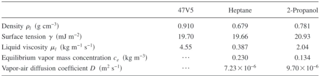
Experiments performed with 47V5 oil, a perfectly wet-ting, nonvolatile fluid, allowed to test the predictions of the above analysis. Note that in these experiments, the tube was first filled completely with silicone oil, which was then drained using the syringe pump. Several drainage steps were realized successively in order to impose several liquid film lengths. For each bulk meniscus position z0, a film thickness
measurement was performed, a long times30 mind after the previous drainage step, to allow the films to relax to their hydrostatic shape. In Figs. 3sad and 3sbd, respectively, the measured film thickness e, made dimensionless by e0, the
film thickness measured after the first drainage step, is shown as a function of the imposed bulk meniscus position
z0for tubes 1 and 2, respectively. It is important to note that
the film thickness measurements were performed at least one tube diameter away from the tube top: at zm= 1 mm for tube 1 and at zm= 0.67 mm for tube 2. These measurements points were chosen arbitrarily sufficiently “far” from the very top of the tube, where some longitudinal curvature effects are visible, as explained in Sec. II. It was checked that the results do not vary significantly with the exact location where the image processing is performed. For z0, Lmax, the theoretical
predictions concerning the film thickness, shown as solid lines in Fig.3, have been obtained using Eq. s4dwith L = z0
and zp= z
m/z0. Theoretically, when the bulk meniscus
posi-tion reaches the value Lmax given by Eq. s5d, the films are
supposed to depin from the tube top. However, the film thickness at the measurement point is not zero at that mo-ment. For z0. Lmax, the theoretical predictions shown in Fig. 3were obtained by assuming that once a film has depinned, its shape does not evolve and is simply translated further down the tube as the bulk meniscus recedes. Consequently, theoretical predictions shown in Fig.3are nonzero up to z0
values equal to Lmax+ zm. The agreement between the experi-ments and the theoretical prediction concerning the film thickness evolution at the measurement point is good. In par-ticular, the maximal film extension is well predicted as the thickness is found to go to zero when z0<Lmax+ zm. Note that the theoretical predictions for r06 the standard
deviation to the average r0valuessee TableId have also been
plotted in Fig. 3 as dotted lines to take into account the uncertainty on the r0 value when comparing the theoretical
predictions to the experimental data.
This simple hydrostatic case highlights the fact that the tube corners’ degree of roundedness is a major parameter to predict the hydrostatic liquid film extension in a square cap-illary tube partially filled with a nonvolatile liquid. In the remainder of this paper, it will be shown that the tube cor-ners’ degree of roundedness is also a key feature in a much more complex situation, namely, when the confined liquid is evaporating.
IV. EVAPORATING LIQUID FILM: MODELING
In this section, a model of evaporation in a capillary tube of square cross section is introduced, the results of which will be compared to experimental results in Sec. V. It is based on the earlier modeling attempts mentioned in Sec. I. The new key feature introduced here is that the present ap-proach allows taking into account the corner internal degree of roundedness. As it will be seen in Sec. V, this is a crucial parameter to consider in order to get quantitative predictions from the model.
A. Modeling and numerical technique
Slow evaporation in stagnant, dry air is considered. Phase change is controlled and limited by vapor diffusion in the surrounding air and the system is assumed to be isother-mal, i.e., the temperature variations due to the evaporation cooling effect are neglected. This assumption is supported by experimental data. Using an infrared thermography technique,9the cooling induced by evaporation can be mea-sured. The cooling is located at the top of the tube, where the phase change takes place until the films depin. The cooling is at most 2.5 K when using 2-propanol in tube 1 and less than 1.5 K for three others cases24s2-propanol in tube 2 and hep-tane in tubes 1 and 2d. These amplitudes of cooling are suf-ficiently small to consider the system to be isothermal, in the range of evaporation rates obtained in the present study. The starting point of the modeling follows the classical analysis of Ransohoff and Radke20for corner flows, relating the liq-uid flow rate in the liqliq-uid films to the liqliq-uid pressure gradient by a Poiseuille-like law corrected for gravity
qliqszd = −rl
AcR2 bml
S
dpl
dz −rlg
D
with 0 , z , z0, s6dwheremlis the liquid viscosity and Acis the sum of the areas of the four liquid corner films and of the four “solid” corners, in a cross section at position zfsee Fig.2sadg
Ac= lR2, s7d with l = 4 −p, for a perfectly wetting liquid in a square cross section tube.14,25 In Eq.s6d,bis a dimensionless flow resis-tance depending on the tube corner shape, the contact angle, and the boundary condition at the liquid-air interface. In the present study, the shear stress on the liquid-vapor interface of the films can be neglected because the liquid viscosity is much larger than that of air. As in Sec. III, the liquid is considered as perfectly wetting on the internal tube wall. The dimensionless flow resistance for a rounded corner was ob-tained in three different studies. Ransohoff et al.20solved the corner flow equation numerically using a finite element method and obtained a discrete set of values for the dimen-sionless flow resistance, depending on the contact angle, the shear stress on the liquid-vapor interface, and the degree of roundedness. An analytical formula is proposed in Zhou
et al.14 using two classical approaches: the hydraulic diam-eter approach and thin film flow theory. In the two aforemen-tioned studies, the dimensionless flow resistance, which is denotedb, is unbounded and diverge when r0/R → 1. A third
approach, initiated by Ayyaswamy et al.29and later revisited by Weislogel and co-workers,21 notably in the case of a rounded corner, has shown that the aforementioned
diver-gence of the hydraulic resistance disappears when using a proper scaling of the problem. However, as mentioned by Chen et al. in their paper, Ransohoff and Radke’s approach remains more widespread. In the present study, the use of this later approach is motivated by the close relation of the present work with the study of evaporation in capillary po-rous media, in which thebformalism is often used6,7and is coherent with previous works of some of the authors.7,9 Figure 4 shows the values of b as a function of r0/R
ob-tained from these three workssthe way to get the value ofb, as defined in the present paper, from the approach of Chen
et al.,21 is detailed in Appendix Ad. The rough shape of the various curves is similar. Notably, they all diverge when
R → r0i.e., when the film thickness tends toward zero.
How-ever, it is worth noting that there are up to a 20% difference inbvalues predicted by these three different approaches for the whole range of r0/Rvalues.
As in Sec. III, liquid pressure and curvature radius are linked by Laplace’s lawsthe longitudinal curvature still be-ing neglectedd. Combinbe-ing Eqs.s2d,s6d, ands7d leads to
qliqszd = −rl lR4 bml
S
gR−2dR dz −rlgD
with 0 , z , z0. s8dDue to evaporation along the films, the liquid flow rate de-creases up to the film tips. As in Yiotis et al.,6the resulting vapor diffusion into the tube is taken into account in the modeling. Here, the mass transfer between the liquid film and the gas phase inside the tube is simply modeled intro-ducing a mean vapor mass concentration c¯, which is a spatial
average of the vapor mass concentration over the tube cross section region occupied by the gas Ag= d2− lR2, and assum-ing the gas mixture as beassum-ing dilute such that the evaporation mass rate per unit of length inside the tube Qev is given by
0 5 10 15 20 0 0.1 0.2 0.3 0.4 0.5 0.6 0.7 0.8 0.9 1 z0(mm) e/ e0
Experimental data points Hydrostatic model, r0= 105 µm Hydrostatic model, r0= 105 ± 2.5 µm a ) 0 10 20 30 40 50 60 0 0.1 0.2 0.3 0.4 0.5 0.6 0.7 0.8 0.9 1 z0(mm) e/ e0
Experimental data points Hydrostatic model, r0= 32 µm
Hydrostatic model, r0= 32 ± 1.5 µm
b )
FIG. 3.sad Dimensionless liquid film thickness e/e0as a function of bulk meniscus position z0 for sad tube 1 and sbd tube 2. Equation s5d gives
Lmax= 12.65 mm for tube 1 and Lmax= 48.2 mm for tube 2.
0 0.2 0.4 0.6 0.8 1 101 102 103 104 105
r
0/R
β
FIG. 4. Hydraulic resistancebas a function of the tube degree of rounded-ness r0/R for a p/2 corner angle, a perfectly wetting liquid and a free boundary condition at the liquid-air interface. Dots: results of Ransohoff and RadkesRef.20d; solid line: results of Zhou et al. sRef.14d; dashed line: results of Chen et al.sRef.21d calculated using the formulas given in
Qev= − 2pDhRce− c¯
d/2 = − 2pDhR
ce− c¯ xRbm
, s9d
where ceis the equilibrium vapor mass concentration at the liquid-gas interface, D the vapor molecular diffusion coeffi-cient, and h = 4 is a dimensionless coefficient of mass transfer provided by three-dimensional computations of the steady diffusion of vapor in the gas phase, inside a square capillary tube partially filled with a perfectly wetting and volatile liquid.30The sensitivity of the numerical results to h will be discussed in Sec. IV B.
The diffusional mass flux in the gas phase qvapis given
by
qvapszd = − DAg
dc¯
dz. s10d
The evaporation rates expected are such that the characteris-tic drying timetdry= dsdz0/dtd−1is much larger than the
char-acteristic diffusion time tdiff= d2/D, so that vapor diffusion
in the tube can be considered as being quasisteady. In the present experiments, the ratio tdry/tdiff is found to be
Os103– 104d. Also, the characteristic time for the interface
shape to reach a steady state is much smaller than tdry,
so that the interface shape variation can be considered as being quasisteady.6 Consequently, one obtains from mass conservation
Qev=dqliq
dz = −
dqvap
dz . s11d
The total mass flux is denoted as qtot, qtot= qliq+ qvapand is
constant along z. Note that because the z-axis is pointing in the same direction as gravity in the present modeling ssee Fig.1d, all the fluxes defined above have negative values.
If we focus on the moment when the film tips depin from the tube top, the two following boundary conditions have to be used:
qvaps0d = qtot, s12d
qliqs0d = 0. s13d
As in the previous hydrostatic analysis, the gravity force is neglected over the bulk meniscus vertical extension. In addi-tion, it is assumed that the liquid flow rate is small enough to consider that the capillary pressure jump at the bulk menis-cus is constant and equal to its static value. Also, the vapor mass concentration on the liquid-gas interface is assumed to be constant and equal to its equilibrium value. The two re-sulting boundary conditions reads
Rsz0d = Rbm, s14d
c
¯sz0d = ce. s15d
The above equations are made dimensionless using the fol-lowing variables:
Rp= R/R
bm, zp= z/L, cp= c¯/ce. s16d Combining Eqs.s8d,s9d, ands11d, a second-order nonlinear ordinary differential equation on Rp is obtained
Rpd 2Rp dzp2 +
S
2 − Rp b db dRpDS
dRp dzpD
2 − Boe−1Rp2 3S
4 −R p b db dRpD
dRp dzp =e −2 bCa hs1 − cpd, s17dwheree= Rbm/L as before and Ca is the capillary number
Ca =2pmlDce
Rbmrllg
. s18d
Combining Eqs.s9d–s11d, another second-order ordinary dif-ferential equation on cpis obtained,
s4x2 − lRp2dd 2cp dzp2− 2lR pdR p dzp dcp dzp= − 2pe −2hRps1 − cpd. s19d
The boundary conditions, Eqs.s12d–s15d, become
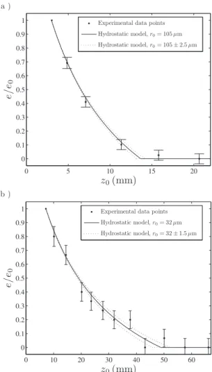
qvapp s0d = q tot p , s20d qliqp s0d = 0, s21d Rps1d = 1, s22d 0 0.2 0.4 0.6 0.8 1 0 0.2 0.4 0.6 0.8 1 z∗ e ∗ Bo = 10−3, ǫ−1= 212 Bo = 5 × 10⁻³, ǫ−1= 95 Bo = 10−2, ǫ−1= 60.6 a ) 0 0.2 0.4 0.6 0.8 1 0 0.2 0.4 0.6 0.8 1 z∗ e ∗ Ca = 10−6, ǫ= 151.7 Ca = 5 × 10⁻⁶, ǫ= 95 Ca = 10−5, ǫ= 71.1 b )
FIG. 5. Dimensionless film thickness ep=sRp− r 0 pd/s1−r
0
pd as a function of the dimensionless zpcoordinate. r
0 p= 0.4,uq
tot
pu=4.5, and the results of Zhou
cps1d = 1, s23d
where the flux are made dimensionless by a reference evapo-ration rate qref= RbmDce and with qtotp = qliqp + qvapp . In order to
close this set of equations the following boundary condition is added:
Rps0d = r 0
p, s24d
traducing the drying of the film tips at depinning, the situa-tion of interest in the present study.
The two coupled Eqs.s17dands19d, along with the cor-responding boundary conditions fEqs. s20d–s24dg, form a boundary value problem with one unknown parametere. An iterative scheme is used to solve this problem. Equations
s17dands19dare solved successively. At each iteration, Eq.
s17d on Rp, with boundary conditions s21d, s22d, and s24d,
and Eq.s19don cp, with boundary conditionss20dands23d,
are solved using theMATLABsolver bvp5c. The parameter e is calculated in the same time as Rp. The maximal relative
error on Rp, cp, andeis 10−6
. The hydraulic resistance as a function of the curvature radius was obtained using either the results of Zhou et al.14 or Chen et al.,21 which provide ana-lytical expressions forb, as opposed to the discrete values of Ransohoff et al.20 As b and Rpb−1db/dRp diverge when Rp
→ r0p, the boundary condition Eq.s24dis in fact applied as Rps0d=xr
0
pwith x = 1.001 which, after several tests, appeared
to be sufficient to obtain a converged solution. Note that in the present numerical procedure, the value of qtot is used as
an input. Three-dimensional numerical simulations of the va-por diffusion problem in the capillary tube, from the menis-cus surface to the stagnant ambient air, could be used to compute the evaporation rate as a function of the bulk me-niscus position and of the full meme-niscus surface shape. Some of the authors reported work in that direction in a recently published paper.8 However, this numerical procedure is heavy and for simplicity, the values of qtotwill be obtained
experimentally in the present study.
B. Numerical results
In Fig. 5, the dimensionless film thickness ep=sRp
− r0pd/s1−r 0
pd is shown as a function of zp for several values
of Bond and capillary numbers. The value of qtotp used is
typical of the values measured at the depinning, for the present experiments ssee Table III in Sec. Vd. The
corresponding dimensionless film length at depinning e−1= L / R
bmis given in the legend. In Fig.5sad, film thickness profiles are shown for several Bond numbers at Ca= 5 3 10−6. The effect of gravity on such profiles is clearly
vis-ible: the corner film profile is all the more thin and short that the Bond number is large. In Fig.5sbd, film thickness profiles are for several capillary numbers at Bo= 5 3 10−3 for the
same set of parameters as in Fig. 5sad. The viscous effects clearly limit the film length.
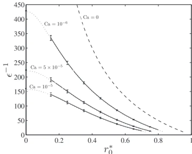
The effect of r0on the film length at depinning, the study
of which is the primary objective of this paper, is displayed in Fig. 6 for different values of the capillary number at a fixed value ofuqtotu and of the Bond number. As might have
been expected from the discussion in Sec. III concerning the hydrostatic nonvolatile liquid case, it is found that the corner
films’ maximal extensionsi.e., obtained at the moment when they depin from the top of the tubed is found to decrease with
r0p. This is an important effect. For instance, for Ca= 10−6, the
film length at depinning is divided by more than a factor of 2 between the case of a perfectly sharp corner and the case of a rounded tube with r0p= 0.4 swhich corresponds to the r0p
value for tube 1, see Table Id. For any value of r0p, it is
important to note that the film extension is finite and much smaller that the one that is obtained in a purely hydrostatic case, when Ca= 0, which highlights how the viscous effects induced by the liquid flow toward the tube top limit the film length. When r0p→ 1, the film length at depinning decreases:
as the present model is no longer valid when the film be-comes so short that the effect of the longitudinal curvature on the film length cannot be neglected, no results for e−1
, 10 are shown in Fig.6. The film length depends weakly on the value of the dimensionless mass transfer coefficient h fsee Eq. s9dg. For instance, for Ca=10−5, Bo= 5 3 10−3, r0p= 0.4,
anduqtotp u=4.5,e −1
varies between 71.2 and 70.6 when h is varied between 2 and 6. This weak dependence of the film length on h is due to the fact that the extension within the tube over which the vapor flow rate qvapis nonzero is always
much shorter than the film length, for all the tested values of
h ssee Fig. 7 belowd. The sensitivity of the obtained film
length to the fixed value of qtotchosen for the computations
at a given Ca and r0p is also shown in Fig. 6. The results
obtained foruqtotu=4.560.45 are plotted as errors bars in Fig. 6. This clearly displays that the film length is mainly con-trolled by the tube roundedness. For instance, at Ca= 5 3 10−6and r
0
p= 0.3, a 10% variation inuq
totu results in a
varia-tion of '3.5% fore−1, whereas a 10% variation in r 0 presults
in a variation of '10% fore−1.
In Sec. V, the predictions of the above model will be tested against experimental data. However, such a compari-son is limited to the film length at depinning only, as the system of coupled equations is solved when the films depin, as expressed by boundary conditionss20d and s21d. Before
0 0.2 0.4 0.6 0.8 1 0 50 100 150 200 250 300 350 400 450
r
∗0ǫ
− 1 Ca = 10−6 Ca = 0 Ca = 5 × 10⁻⁵ Ca = 10−5FIG. 6. Dimensionless liquid film lengthe−1= L / R
bm as a function of the
dimensionless degree of roundedness r0pfor various Ca numbers. Solid and dashed lines correspond to the results of the complete model and the dotted lines to those of the simplified modelssee Sec. IV Cd. The dots indicated for
r0p= 0 are the results given by the complete model in the case of a perfectly sharp corner. For all the curves, Bo= 5 3 10−3,uq
tot
pu=4.5, and the results of Zhou et al. were used forb.
that moment, the flow rate distribution between the gas and liquid phasesi.e., the ratio between qliqand qvapd at the film
tip is not known and thus the model cannot be used to make any predictions on the film length. However, as can be seen in Fig.7sad, where the vapor mass concentration profiles in the tube are shown for the same set of parameters as in Fig.
5sad, the gas phase is saturated over much of the film length: the vapor concentration gradients are only significant near the tube entrance region for 0 , zp, 0.1. Consequently, the
phase change occurs preferentially at the film tip: the vapor mass flux is nonzero only in the near tube entrance region, as seen in Fig. 7sbd, which shows the absolute value of the dimensionless vapor mass flux qvapp as a function of zp. In the
following, a simpler model is proposed, in which vapor dif-fusion is neglected in the tube: the air is considered to be saturated in vapor inside the tube, so that qvapp = 0 at any zp. 0. Consequently, the liquid flow rate is assumed to be
constant along the tube. This model is similar to the one proposed in Chauvet et al.9and it is shown below that it can predict the evolution of the film thickness during the whole experiment and not only at the moment when the films depin.
C. A simpler model
With the additional assumption on the saturation of air with vapor inside the tube, the problem amounts to a single differential equation, obtained by rewriting Eq.s8das
dz˜ dRp=
S
Ca 2pqtot p bRp−2+ BoRp2D
−1 , s25dwhere now z˜ = z / Rbm. Using qtot as an input and solving
Eq.s25dusing a finite difference scheme with the boundary condition
z
˜ = 0 at Rp= xr 0
p, with x= 1.001 s26d
leads to a prediction of the film length at depinning, which is then e−1
= z˜sRp= 1d. Equation s25d can also be solved using
the following boundary condition:
z
˜ = z˜0 at Rp= 1, s27d
using the measured qtotand film length as inputs in order to
get the film thickness profile Rpsz˜d.
The predictions of this simple model as far as the film length at depinning is concerned, i.e., using boundary condi-tion s26d, are shown as dotted lines in Fig. 6. The simple model provides film lengths very close to the complete model predictionsssolid lines in Fig.6d for a wide range of
capillary numbers, Bond numbers, and total evaporation rate values. It can be noted that the film lengths given by this simplified model are always slightly lower than those ob-tained with the previous approach sthe maximal difference for the results presented in Fig. 6 is 2.5Rbm for the Ca= 10−6case, at r
0
p= 0.15d. Indeed, in the simple model, the
liquid flow rate is constant along the entire film length. Therefore, it can be argued that in this case, the liquid pres-sure gradient dpl/dz, in the film tip region, is larger than the one obtained using the previous model. As dpl/dz~ −df1/Rszdg/dz, the radius of curvature gradient is then lower in the previous model than in the simplified model, leading to larger film length at depinning. It is also important to notice that even if this simplified model is in good agreement with the previous one as far as film length at depinning is concerned, it predicts a divergence of the dimensionless liq-uid mean velocity at the film tip vp ssee Fig.8d, where
0 0.05 0.1 0.15 0.2 0.25 0.4 0.5 0.6 0.7 0.8 0.9 1 z∗ c ∗ Bo = 10−3, ǫ−1= 212 Bo = 5 × 10⁻³, ǫ−1= 95 Bo = 10−2, ǫ−1= 60.6 a ) 0 0.05 0.1 0.15 0.2 0.25 0 1 2 3 4 5 z∗ ¯ ¯ q ∗ va p ¯ ¯ Bo = 10−3, ǫ−1= 212 Bo = 5 × 10⁻³, ǫ−1= 95 Bo = 10−2, ǫ−1= 60.6 b )
FIG. 7.sad Dimensionless vapor mass concentration cpas a function of zp. sbd Absolute value of the dimensionless vapor mass flux qvapp as a function of
zp. These results are obtained using Ca= 5 3 10−6, r 0 p= 0.4,uq
tot
pu=4.5, and the results of Zhou et al. forb.
0 0.2 0.4 0.6 0.8 1 0 10 20 30 40 50
z
∗|v
∗|
FIG. 8. Absolute value of the dimensionless liquid mean velocityuvpu as a function of zp. These results are obtained using Bo= 10−2, Ca= 5 3 10−6,
r0p= 0.4,uqtotpu=4.5, and the results of Zhou et al. forb. Solid line: complete model; dotted line: simplified model.
vp= qliq/frllsR2− r0 2dg qref/frllsRbm2 − r02dg= qliq p 1 − r0 p2 Rp2− r 0 p2. s28d
Indeed, since the liquid flow rate is constant along the film and since the liquid cross section at the film tip is 0, a diver-gence of vpis found at the film tip. On the contrary, as the
complete model takes into account evaporation along the films, it predicts a more realistic zero liquid mean velocity at the film tipssee Fig.8d.
V. EXPERIMENTAL RESULTS AND COMPARISONS WITH THE MODELS PREDICTIONS
A typical evolution of the bulk meniscus location z0as a
function of time is shown in Fig. 9 for heptane in tube 2. Three distinct periods can be seen. First, as long as
z0, 17 mm, the evaporation rate is roughly constant. Then,
around z0<17 mm, the evaporation rate starts to decrease
and this corresponds to the moment when the films depin from the tube’s opened end, as can be checked visually on the recorded images. For this given experiment, the film tip depinnings do not occur exactly at the same time and the moment when the first and last film depinning occur are indicated in Fig.9 snote that only three corner films out of
four can be detected on the high magnification images, see Sec. IIId. Finally, after the film depinnings, the film tips re-cede inside the tube. Consequently, the distance between the film tips and the tubes’ opened end increases, provoking an increase in the diffusive resistance to mass transfer and thus a continuous decrease of the evaporation rate, as can seen in Fig.9for z0. 17 mm. A more detailed analysis of this kind
of curve can be found in Chauvet et al.8
We now turn to the comparison between the experimen-tal data and the model, as far as the film length at depinning is concerned. To allow for such a comparison, the evapora-tion rate, made dimensionless by dividing by qref= RbmDce, has to be used as an input for the modelfsee boundary Eq.
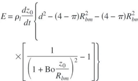
s20dg. The evaporation rate is estimated as
E=rl dz0 dt
5
d 2 −s4 −pdRbm 2 −s4 −pdRbm 2 33
1S
1 + Bo z0 RbmD
2− 146
s29dssee Appendix Bd. The dz0/dt value is calculated as the
value at zd of the derivative of the best-fitting second-order polynomial of the data points z0std in the range fzd− 1 mm,
zd+ 1 mmg, where zd is the bulk meniscus position at the depinning. When a differential depinning of the observed films occurs, the data points z0std in the range fzd,f− 1 mm, zd,l+ 1 mmg are fitted by a second-order polynomial, which is
then used to compute dz0/dtat zd,f and zd,l. Here, zd,f and zd,l
are the bulk meniscus positions observed at the first and last depinning. Two dimensionless evaporation rates are then cal-culated, qtot,fp and q
tot,l
p , corresponding, respectively, to the
evaporation rate measured when the first and last film depin-nings are observed, made dimensionless by dividing by qref.
For a given couple tube fluid, several experiments were per-formed, each one leading to one or two values for the dimen-sionless evaporation rate depending on the occurrence or not of a differential depinning. All these values were then aver-aged to get a unique dimensionless evaporation rate qtotp to be
used in the model, the uncertainty on this parameter being taken as the standard deviation on this average. Similarly, the film lengths at depinning were measured in each experiment, leading to one szdd or two values in case of differential de-pinningszd,f and zd,ld. All these values were then averaged to
get a unique film length Ld, the uncertainty on this parameter being taken as the standard deviation on this average. The values for qtotp , Ld, the corresponding experimental uncertain-ties, along with the capillary and Bond numbers calculated using the fluid properties given in Table I, are given in TableIII.
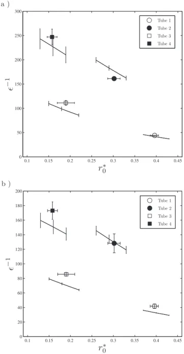
Figures10sadand10sbd, respectively, show the predicted value of e−1
= Ld/Rbm at depinning as a function of r0p,
to-gether with the present experimental measurements for hep-tane and 2-propanol, respectively. The theoretical predictions fshown as lines in Figs.10sadand10sbdg are obtained using the result of Zhou et al.14for b. For the sake of clarity, the theoretical predictions obtained using the result of Chen
et al.21forbare not shown. Note that they do not differ from the ones obtained using the results of Zhou et al. by more than 5.4%. The vertical error bars on the theoretical predic-tions come from the uncertainty on qtotp . The theoretical
pre-diction were computed only for a restricted range of r0p
around the experimental value for the tube considered. The data points are shown as isolated symbols: squares for the experiments performed with tubes 3 and 4 shaving the smaller r0d and circles for the experiments performed with
tubes 1 and 2. The uncertainty on the degree of roundedness of the tube internal corners is shown as a horizontal error bar for the experimental data and the uncertainty one−1is due to
the experimental uncertainty on Ld.
The tube internal corner degree of roundedness has a huge impact on the film length at depinning. For instance, Ld
0 2000 4000 6000 8000 10000 0 5 10 15 20 25 30 35
Time (s)
z
0(m
m
)
Last depinning First depinningFIG. 9. Bulk meniscus evolution as a function of time for heptane in tube 2. The moment when the first and last film depinnings are observed are indi-cated on the graph.
is roughly twice larger in tube 3 than in tube 1, which having approximately the same internal size d but, respectively, with
r0p= 0.396 and r 0
p= 0.187 for the two fluids used. For all the
data points considered, the agreement between the experi-mental results and the simulation results is good: the mean difference between the data points and the theoretical predic-tions is 12% when using the results of Zhou et al. forband 12.7% when using the results of Chen et al. Thus, the present modeling captures correctly the fact that the internal round-edness of the capillary tubes is the key factor controlling the film maximal length. Another point to mention is that the differential depinning sometimes observed in the present ex-periments could then simply be due to slight differences in the tube corners’ degrees of roundedness, the “roundest” cor-ner depinning first.
In the following, we compare the model predictions to the experimental data, as far as the film thickness evolution
before depinningis concerned. As mentioned in Sec. IV, the first model presented predicts only the film length at depin-ning whereas the simpler, second model can be used before the film depinning, using the evaporation rate and the film length as inputs. For a given bulk meniscus position before the film depinning, the film length is simply L = z0std. When
computing the evaporation rate using Eq. s29d, the dz0/dt
value is obtained by finite difference, after filtering the z0std
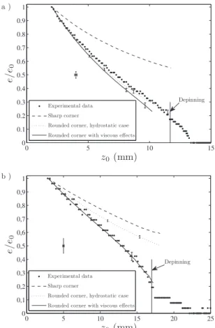
data with a Savitzky–Golay filter. The experimental results are compared to several theoretical predictions, made at the measurement point location. As the model gives the film shape until the film thickness cancels at z = 0, the theoretical predictions shown here do not go to zero. The film length predicted at depinning, already shown in Fig.10, can be read in Fig.11as the z0value corresponding to the last point of a
given theoretical curve. We also note that because the film thickness measurement is not performed at the tube top but at z / d = 1 in both cases, the film thickness does not fall to zero at the film depinning, which is detected at z = 0 on the high magnification images and the moment of which is indi-cated on Fig. 11. Rather, the experimental data evolution after the depinning displays the shape of the liquid film tip as it passes in front of the measurement point.
First, we compare the experimental results to the model predictions for a hydrostatic case, i.e., taking Ca= 0 in Eq.
s25dfdotted line in Figs.11sadand11sbdg. A good agreement is found between the model and the whole experimental data
TABLE III. Experimental data.
Ca Bo uqtotpu dqtotp Ld smmd smmddLd Tube 1: Isopropanol 4.523 10−6 2.573 10−2 3.71 0.21 11.1 0.8 Tube 2: Isopropanol 1.133 10−5 4.113 10−3 2.66 0.24 13.6 1.4 Tube 1: Heptane 1.323 10−6 2.383 10−2 4.47 0.12 11.7 0.05 Tube 2: Heptane 3.313 10−6 3.813 10−3 4.69 0.32 17.1 0.5 Tube 3: Isopropanol 4.743 10−6 2.343 10−2 3.36 0.23 21.6 0.65 Tube 4: Isopropanol 9.253 10−6 6.153 10−3 3.14 0.44 22.45 1.55 Tube 3: Heptane 1.393 10−6 2.173 10−2 3.86 0.68 28.01 1.27 Tube 4: Heptane 2.703 10−6 5.703 10−3 4.07 0.92 32.03 2.11 0.1 0.15 0.2 0.25 0.3 0.35 0.4 0.45 0 50 100 150 200 250 300
r
∗0ǫ
− 1 Tube 1 Tube 2 Tube 3 Tube 4 a ) 0.1 0.15 0.2 0.25 0.3 0.35 0.4 0.45 0 20 40 60 80 100 120 140 160 180 200r
∗0ǫ
− 1 Tube 1 Tube 2 Tube 3 Tube 4 b )FIG. 10. Dimensionless film length at depinninge−1= L
d/Rbmas a function
of r0pforsad heptane and for sbd isopropanol in the four tubes considered. The theoretical predictions are shown as solid lines for all cases for a limited range of r0p. The theoretical prediction associated with a given experimental case is the one closest to the corresponding data point.
for tube 1, whereas in tube 2 the agreement is correct until
e / e0<0.8. In tube 1, the film thinning is then mainly due to
gravity effect, whereas in the smaller tube 2, the discrepancy between a purely hydrostatic prediction and the data means that some viscous effects start to manifest when the films are getting thin enough. In this latter case, the theoretical predic-tions obtained when taking into account the viscous effect in the modelssolid line in Fig.11d significantly differs from the
hydrostatic casefwhich is not the case for tube 1, see Fig.
11sadg and agrees within errors bars with the experimental data. Note that the same conclusions can be drawn when using the results of Chen et al. forbrather than the results of Zhou et al. To highlight the crucial importance of the internal corner degree of roundedness, we also plotted the theoretical prediction for a perfectly sharp corner, r0= 0. Then, the
model clearly fails: the film thickness predicted is much larger than the one observed and also, it is not zero at the tube top, i.e., no depinning is observed.
VI. CONCLUSION
Liquid films trapped by capillarity in the corners of a square cross section capillary tube have a great impact on the evaporation kinetics of a volatile liquid contained in the tube. They provide paths for the liquid between the receding bulk meniscus and the entrance of the tube. The capillary
pump-ing of the volatile liquid from the bulk meniscus to the tube opened end where it evaporates is the key point in explaining the much faster evaporation rate obtained in a square capil-lary tubescompared to a circular cross section tubed. In this paper, we have shown that the degree of roundedness of the tube internal corners is a key factor in controlling the corner films’ maximal extension, i.e., the films’ length for which the films are found to depin from the tube and to start to recede inside the tube. The tube internal roundedness provides a lower limit value for the corner films’ transverse curvature and the viscous resistance to the corner flow diverges when the liquid films thin down until they perfectly match the internal corner shape. Experimental results are in good agreement with a simple model of corner flow that take into account the tube internal roundedness, as far as the maximal films’ length and also the films’ thickness evolution before the films’ depinning are concerned.
This study highlights how a seemingly insignificant geo-metrical detail, the tube corners’ roundedness, has a great influence on the evaporation of a volatile liquid contained in a square capillary tube. From here, one can appreciate how challenging the prediction of evaporation rate for a porous medium must be, where a precise knowledge of the pore space geometry is often out of reach experimentally and also difficult to model. Corner roundedness will certainly have a dramatic influence for others corner flow situations, such as the one typically encountered when describing microheat pipes. For instance, the dry out conditionsslocation and criti-cal heat fluxd should be influenced by the change in the vis-cous resistance to the flow into the wedge, when a slight roundedness of the wedge corner is present.
ACKNOWLEDGMENTS
Financial support from GIP ANR “Intensifilm” sProject No. ANR-06-BLAN-0119-01d is gratefully acknowledged.
APPENDIX A: EXPRESSION OBTAINED FOR THE HYDRAULIC RESISTANCE b USING THE RESULTS OF CHEN et al.
In this short appendix, how to get the hydraulic resis-tance expressed using the b formalism of Ransohoff and Radke20 from the results Chen et al.21 is shown explicitly. Using the notations and the results of Chen et al., the hy-draulic resistanceb can be expressed as31
b= f 2 Fi 1 + Tc 2 s1 − r0pd 2T c 2
H
1 −F
r0p hps1 − r 0 pd + r 0 pG
2J
−1 , sA1dwhere f = sina/scosa− sinad, Tc= tana+ fdr
0 p/s1−r 0 pd, d =p/2 −a−u, and hp=sR−r 0d/sRbm− r0d. The variable Fi is given by Fi= W 3 Fsa,u,hp,r0pd, sA2d
where the function F can be found in Chen et al. and W is a coefficient which depends on hp and r
0
p. The values of W
used to computeb as a function of r0p were obtained from
Fig.11 of Chen et al. for hp= 1 / 2.
0 5 10 15 0 0.1 0.2 0.3 0.4 0.5 0.6 0.7 0.8 0.9 1 z0(mm) e/ e0 Experimental data Sharp corner
Rounded corner, hydrostatic case Rounded corner with viscous effects
Depinning a ) 0 5 10 15 20 25 0 0,1 0,2 0,3 0,4 0,5 0,6 0,7 0,8 0,9 1 z0(mm) e/ e0 Experimental data Sharp corner
Rounded corner, hydrostatic case Rounded corner with viscous effects
Depinning b )
FIG. 11. Dimensionless film thickness e / e0as a function of z0for heptane in sad tube 1 at z=1 mm and sbd tube 2 at z=0.4 mm. The experimental error bars for the data points are shown on a distinct point, for the sake of clarity. The results of Zhou et al. were used to computeb. The vertical errors bars on the theoretical predictions come from the uncertainty on the value of r0p used in the model.
APPENDIX B: DERIVATION OF AN APPROXIMATED EXPRESSION FOR THE EVAPORATION RATE
In this appendix, the calculation leading to Eq. s29d is detailed. The evaporation rate spositive and expressed in kg s−1d is defined by
E= −rl
dsVr+ Vcd
dt , sB1d
where Vr=fH−z0stdgd2 is the volume of liquid contained in
the fully saturated part of the tube of vertical extension H and Vc=e0
z0stds4−pdR2fz,z
0stdgdz is the volume of liquid
trapped in the corners films snote that the present analysis leads to identical results when the interior corners rounded-ness, which is neglected here, is taken into accountd. Then,
dsVr+ Vcd dt = − d 2dz0 dt +s4 −pd d dt
E
0 z0std R2fz,z0stdgdz, sB2d with d dtE
0 z0std R2fz,z0stdgdz = dz0 dtR 2fz = z 0std,z0stdg +E
0 z0std d dtR 2fz,z 0stdgdz, sB3dso that finally, using Rfz=z0std,z0stdg=Rbm,
E= −rl dsVr+ Vcd dt =rl dz0 dt
F
d 2 −s4 −pdRbm 2 −s4 −pd 3E
0 z0std d dz0 R2fz,z0stdgdzG
. sB4dThe integral appearing in Eq.sB4dcannot be computed ex-plicitly without knowledge of the shape of corner films, i.e., of Rfz,z0stdg. Assuming that the corner films’ shape is simply
given by a balance between gravity and capillary forcessi.e., neglecting viscous effectsd,
1 Rfz,z0stdg = 1 Rbm −rlg g fz − z0stdg, sB5d and finally, E=rl dz0 dt
5
d 2 −s4 −pdRbm 2 −s4 −pdRbm 2 33
1S
1 + Bo z0 RbmD
2− 146
. sB6dThe third term appearing in Eq. sB6d becomes significant compared to the second one when the corner films are suffi-ciently elongated, i.e., when Bo z0/Rbmis no longer !1. For instance, at the end of a typical experiment considered in this
paper using tube 1 with isopropanol, z0/d is '10 close to
depinning so that Bo z0/Rbm<1.
EquationsB6dfor E is a good approximation for tubes 1 and 3, which are large enough so that viscous effects are negligiblescf. Fig. 11and related discussiond. As far as the
smaller tubes used in this study are concernedstubes 2 and 4d, the use of Eq. sB5d to describe Rfz,z0stdg is more
ques-tionable as viscous effects are clearly displayed experimen-tally for these tubesscf. Fig.11d. Consequently, the meniscus
shape results from a balance between capillary, gravitary, and viscous effects and cannot be computed explicitly. However, as the Ca numbers are very small in the present study sbe-cause of the small evaporation ratesd, it may be expected that using Eq.sB6d should provide a precise enough estimate of the evaporation rate in the small tube case. Also, it must be noted that the two last terms in the right-hand side of Eq.
sB6d, and notably the problematic third one, always represent a small correction to the first one, ass4−pdRbm2 <0.06d2.
1
C. B. Sobhan, R. L. Rag, and G. P. Peterson, “A review and comparative study of the investigations on micro heat pipes,”Int. J. Energy Res. 31,
664s2007d. 2
M. Prat, “Recent advances in pore-scale models for drying of porous me-dia,”Chem. Eng. Sci. 86, 153s2002d.
3
V. S. Ajaev and G. M. Homsy, “Modeling shapes and dynamics of con-fined bubbles,”Annu. Rev. Fluid Mech. 38, 277s2006d.
4
T. M. Squires and S. R. Quakes, “Microfluidics: Fluid physics at the nano-liter scale,”Rev. Mod. Phys. 77, 977s2005d.
5
J. B. Laurindo and M. Prat, “Numerical and experimental network study of evaporation in capillary porous media. Drying rates,”Chem. Eng. Sci.
53, 2257s1998d.
6
A. G. Yiotis, A. G. Boudouvis, A. K. Stubos, I. N. Tsimpanogiannis, and Y. C. Yortsos, “The effect of liquid films on the drying of porous media,”
AIChE J. 50, 2721s2004d.
7
M. Prat, “On the influence of pore shape, contact angle and film flows on drying of capillary porous media,”Int. J. Heat Mass Transfer 50, 1455
s2007d. 8
F. Chauvet, P. Duru, S. Geoffroy, and M. Prat, “Three periods of drying of a single square capillary tube,”Phys. Rev. Lett. 103, 124502s2009d.
9
F. Chauvet, S. Cazin, P. Duru, and M. Prat, “Use of infrared thermography for the study of evaporation in a square capillary tube,”Int. J. Heat Mass Transfer 53, 1808s2010d.
10
J. Stefan, “Uber das gleichgewicht und die bewegung in besondere die diffusion von gasgemengen,” Sitzungsber. Akad. Wiss. Wien, Math.-Naturwiss. Kl., Abt. 2A 63, 63s1871d.
11
R. B. Bird, W. E. Stewart, and E. N. Lightfoot, Transport Phenomena sWiley, New York, 2002d.
12
P. Concus and R. Finn, “On the behavior of a capillary surface in a wedge,”Proc. Natl. Acad. Sci. U.S.A. 63, 292s1969d.
13
Y. Pomeau, “Wetting in a corner and related questions,”J. Colloid Inter-face Sci. 113, 5s1986d.
14
D. Zhou, M. Blunt, and F. Orr, “Hydrocarbon drainage along corners of noncircular capillaries,”J. Colloid Interface Sci. 187, 11s1997d.
15
M. Dong and I. Chatzis, “The imbibition and flow of a wetting liquid along the corners of a square capillary tube,”J. Colloid Interface Sci.172,
278s1995d. 16
B. Suman, S. De, and S. DasGupta, “A model of the capillary limit of a micro heat pipe and prediction of the dry-out length,”Int. J. Heat Fluid Flow 26, 495s2005d.
17
L. Yang and G. M. Homsy, “Steady three-dimensional thermocapillary flows and dryout inside a v-shaped wedge,” Phys. Fluids 18, 042107
s2006d. 18
M. Markos, V. S. Ajaev, and G. M. Homsy, “Steady flow and evaporation of a volatile liquid in a wedge,”Phys. Fluids 18, 092102s2006d.
19
R. Savino and D. Paterna, “Marangoni effect and heat pipe dry-out,”Phys. Fluids 18, 118103s2006d.
20
T. Ransohoff and C. Radke, “Laminar flow of wetting liquid along the corners of a predominantly gas-occupied noncircular pore,”J. Colloid In-terface Sci. 121, 392s1988d.