HAL Id: hal-00862351
https://hal-iogs.archives-ouvertes.fr/hal-00862351
Submitted on 16 Sep 2013
HAL is a multi-disciplinary open access
archive for the deposit and dissemination of
sci-entific research documents, whether they are
pub-lished or not. The documents may come from
teaching and research institutions in France or
abroad, or from public or private research centers.
L’archive ouverte pluridisciplinaire HAL, est
destinée au dépôt et à la diffusion de documents
scientifiques de niveau recherche, publiés ou non,
émanant des établissements d’enseignement et de
recherche français ou étrangers, des laboratoires
publics ou privés.
Bragg thickness criterion for intracavity diffraction
gratings
Ludivine Menez, Isabelle Zaquine, Alain Maruani, Robert Frey
To cite this version:
Ludivine Menez, Isabelle Zaquine, Alain Maruani, Robert Frey. Bragg thickness criterion for
intra-cavity diffraction gratings. Journal of the Optical Society of America B, Optical Society of America,
2002, 19 (5), pp.965. �hal-00862351�
Bragg thickness criterion for intracavity
diffraction gratings
Ludivine Menez, Isabelle Zaquine, and Alain Maruani
De´partement Traitement du Signal et de l’Image, Ecole Nationale Supe´rieure de Te´le´communications, 46 Rue Barrault, 75634 Paris Ce´dex 13, France
Robert Frey
De´partment Traitement du Signal et de l’Image, Ecole Nationale Supe´rieure de Te´le´communications, 46 Rue Barrault, 75634 Paris Ce´dex 13, France, and Laboratoire Charles Fabry de l’Institut d’Optique, Institut d’Optique The´orique et Applique´e, and Centre National de la Recherche Scientifique, Bat. 503,
B.P. 147, 91403 Orsay Ce´dex, France
Received August 7, 2001; revised manuscript received November 12, 2001
The grating thickness limit lFPbetween the Raman–Nath and the Bragg diffraction regimes is calculated for an index grating placed in an asymmetric Fabry–Perot resonator with a totally reflecting back mirror and compared with that which was obtained for the same grating with no cavity lM. Owing to the increase of the
effective interaction length inside the Fabry–Perot cavity, the stronger the front mirror reflectivity R1of the cavity, the smaller the thickness above which the whole diffracted intensity can be concentrated into one unique diffracted beam: lFP⫽ 关(1 ⫺冑R1)/(1⫹冑R1)兴lM/2. © 2002 Optical Society of America
OCIS codes: 090.1970, 090.7330, 190.4360.
1. INTRODUCTION
The diffraction of light on holograms is of interest for fun-damental reasons and because of its applications to opti-cal signal processing.1,2 Although Raman–Nath diffrac-tion on thin holograms is quite useful, Bragg diffracdiffrac-tion on thick gratings is probably more interesting because then diffracted light is condensed into one unique mode, provided that the incidence angle and wavelength of the read beam fulfill the so-called Bragg resonance condition. The transition between Raman–Nath and Bragg diffrac-tion regimes has been studied extensively for simple gratings.3–8 The most commonly used thickness crite-rion is that the grating thickness be larger than some threshold, depending on the grating period and on the light’s wavelength, to be in the Bragg regime where higher diffraction orders become vanishingly small.
However, even in the Bragg regime the diffraction properties of gratings are often limited by the small refractive-index changes that can be induced or by the thinness of the nonlinear materials. It has been shown9–12that one can overcome these limitations by put-ting the graput-ting into a Fabry–Perot resonator. Strong improvement results when it is assumed that all the dif-fracted energy is concentrated into the main diffraction order. The diffraction regime must therefore be exam-ined, and our aim in this paper is to derive a thickness criterion for the intracavity model.
The intensities of the higher-order diffraction modes are therefore calculated, and it is shown that, for intra-cavity as well as for conventional bare gratings, there is a minimum thickness above which these intensities are negligible. The model used to describe intracavity Bragg
gratings is described in Section 2; all diffracted orders, even though the read beam is incident at the Bragg angle, are taken into account. The Bragg criterion is discussed in Section 3; the conventional bare grating is considered the limit where the resonator mirror reflection coefficients are zero. In Section 4 the situation of double resonance is examined, for which the main and the first higher-order diffraction modes both fulfill the Fabry–Perot resonance condition.
2. INTRACAVITY BRAGG GRATING: THE
MODEL
A. Description of the Device
The model used for the derivation of the Bragg criterion is a direct extension of the one developed by Menez et al.9to calculate the diffraction efficiency of intracavity Bragg gratings. In such an intracavity holographic device the lossless refractive-index grating is placed in a Fabry– Perot resonator; the grating fringes are parallel to the z axis, whereas the cavity mirrors are parallel to the x axis of our coordinate system (see Fig. 1). We consider a sinu-soidal grating characterized by its average refractive in-dex n0, its refractive-index modulation⌬n, and its
spa-tial period⌳ ⫽ 2/K such that
n⫽ n0⫹ ⌬n sin共K • r兲
⫽ n0⫹
⌬n
2i 关exp共iK • r兲 ⫺ exp共⫺iK • r兲兴. (1) The resonator has a thickness l and is composed of two mirrors with amplitude reflectivities r1 and r2, which
may be complex.
B. Wave Equation and Phase-Matching Conditions
An incident plane and monochromatic read wave EIwith
wavelength 0 and Bragg resonant refraction angle
⫽ arcsin(/2⌳) inside the cavity produces reflected and transmitted waves (ER, ET) and reflected and
transmit-ted diffractransmit-ted waves (ERDpand ETDp), where p is the
dif-fraction order. The amplitudes of the forward intracavity read and pth-order diffracted waves are, respectively, RF
and SFp. Their wave vectors are kF and kFp⬘,
respec-tively. The backward waves, which are due to reflection on the mirrors, have subscripts B instead of F (see Fig. 1). Propagation anglesp of the diffracted waves are
deter-mined by the Raman–Nath relation
k共sinp ⫺ sin兲 ⫽ pK, (2)
where k⫽ 2/, with ⫽ 0/n0, and K⫽ 2/⌳ is also
related to sin, which yields
sinp⫽ 共2p ⫹ 1兲sin. (3)
The highest possible diffraction order pmaxis limited by
兩共2pmax⫹ 1兲sin兩 ⭐ 1. (4)
This means that diffraction orders 1 and ⫺2 can exist only for internal read angles smaller than max
⫽ arcsin(1/3) ⯝ 19.5°, and the smaller the angle, the more diffraction orders in the nonlinear medium.
In the nonlinear medium the wave equation is
ⵜRF• kˆFexp共ikF• r兲 ⫹ ⵜRB• kˆBexp共ikB• r兲 ⫹
兺
p⫽0 p⫽⫺pmax pmax 关ⵜSFp• kˆF⬘p ⫻ exp共ikF⬘p• r兲ⵜSBp• kˆB⬘pexp共ikB⬘p• r兲] ⫽ 2i 0再
n0⫹ ⌬n 2i 关exp共iK• r兲 ⫺ exp共⫺iK • r兲兴冎
⫻再
ⵜRF• kˆFexp共ikF• r兲 ⫹ ⵜRB• kˆB ⫻ exp共ikB• r兲 ⫹兺
p⫽0 p⫽⫺pmax pmax 关ⵜSFp• kˆF⬘p⫻ exp共ik⬘Fp• r兲 ⫹ ⵜSBp• kˆ⬘Bpexp共ikB⬘p• r兲兴
冎
,(5) where kˆ are unit vectors of the corresponding direction k. Equation (5) is equivalent to a system of 2 ⫻ (2pmax
⫹ 1) coupled equations, each corresponding to a different wave vector. The sinusoidal form of the grating is char-acterized by its Fourier components K and ⫺K, which means that diffraction by this grating directly couples any
p-order mode only to ( p ⫺ 1)- and ( p ⫹ 1)-order modes.
In these conditions, only orders 1 and⫺1 are coupled to the read wave (order 0) and therefore give rise to high dif-fraction efficiencies. The higher-order modes coupled to diffracted waves are necessarily less important. To se-lect the significant terms of each equation properly we must have a clear view of the phase-matching conditions. Figure 2 shows the various wave vectors of the Raman– Nath diffraction orders. The circle diameter is k. The Raman–Nath relation [Eq. (2)] imposes phase matching along the x axis, as all the x projections of the wave vec-tors differ from one another by an integer number of K, and no x dependence of the amplitude is taken into
ac-Fig. 1. Intracavity Bragg grating. The nonlinear medium where the grating is recorded is inserted into a Fabry–Perot resonator. An incident read wave EIgives rise to reflected ER,
transmitted ET, and diffracted ERDand ETDwaves, the numbers
in whose subscripts indicate their diffraction order. The intrac-avity wave vectors of the read and diffracted waves are, respec-tively, k and k⬘. They bear the subscripts F for forward propa-gating and B for backward propapropa-gating. For simplicity, refraction is not taken into account in this figure.
Fig. 2. Phase matching. The forward and backward wave vec-tors of the read wave, kFand kB, and grating wave vector K are represented as well as all diffracted waves kF⬘ and kB⬘
(num-bered by their diffraction orders), according to the Raman–Nath relation.
count. RF, RBand SFp, SBpare therefore functions of z
only. A phase mismatch along the z direction implies rapid attenuation of the corresponding wave and can be tolerated only in the case of a thin sample; the object of this study is to determine how thin that is. The⫺1 dif-fraction order is the only phase-matched mode to the for-ward incident wave as⫺1⫽ ⫺, whereas the 兩 p兩 diffrac-tion order is phase matched to the ⫺兩 p兩 ⫺ 1 diffraction order as⫺兩 p兩⫺1⫽ ⫺兩 p兩. The phase mismatch k(cosp
⫺ cosp⫹1)z increases with 兩 p兩; this is one more clue to
help us in the simplification of Eq. (5).
We finally get two sets of four coupled propagation equations, which relate the amplitudes of order 0; of the main diffracted beam, order ⫺1; and of the first two higher diffraction modes, order 1 and order ⫺2. More-over, only the terms that have the smallest phase mis-match ⌬kz ⫽ k(cos ⫺ cos 1)z⫽ k(cos ⫺ cos ⫺2)z are
kept in each equation:
cosdRF dz ⫽ ⌬n 0 关SF⫺1⫺ SF1exp共⫺i⌬kz兲兴, (6) cos dSF⫺1 dz ⫽ ⌬n 0 关⫺RF⫹ SF⫺2exp共⫺i⌬kz兲兴, (7) cos1 dSF1 dz ⫽ ⌬n 0 关RFexp共i⌬kz兲兴, (8) cos1 dSF⫺2 dz ⫽ ⌬n 0 关⫺SF⫺1exp共i⌬kz兲兴; (9) ⫺cosdRB dz ⫽ ⌬n 0 关SB⫺1⫺ SB1exp共i⌬kz兲兴, (10) ⫺cosdSB⫺1 dz ⫽ ⌬n 0 关⫺RB⫹ SB⫺2exp共i⌬kz兲兴, (11) ⫺cos1 dSB1 dz ⫽ ⌬n 0 关RBexp共⫺i⌬kz兲兴, (12) ⫺cos1 dSB⫺2 dz ⫽ ⌬n 0 关⫺SB⫺1exp共⫺i⌬kz兲兴. (13) The last step before solving these equations is to write the boundary conditions on the cavity mirrors to relate the forward-propagating waves to the backward waves on each side of the resonator (z ⫽ 0 and z ⫽ l):
SF1共0兲 ⫽ r1SB1共0兲, (14)
SF⫺2共0兲 ⫽ r1SB⫺2共0兲, (15)
r2SF1共l兲 ⫽ SB1共l兲exp共⫺2ikl cos1兲, (16)
r2SF⫺2共l兲 ⫽ SB⫺2共l兲exp共⫺2ikl cos1兲. (17)
C. Equation Resolution
Coupled differential equations (6)–(13) cannot be simply solved analytically, and we have calculated the ampli-tudes of the higher-order modes in two ways.
The first one treats the system in matrix form. The unknown is a vector whose components are the four am-plitudes of the relevant waves:
d dz
冉
SF1 RF SF⫺1 SF⫺2冊
⫽ 关u兴冉
SF1 RF SF⫺1 SF⫺2冊
, (18)where [u] is a 4 ⫻ 4 matrix. The matrix differential equation can then be integrated by the Peano–Baker method,13and the four modes that are considered are cal-culated in one step.
The second way is the method of successive approxima-tions.14 We used the expressions of the read and⫺1 dif-fraction order waves given in Ref. 9 to calculate the higher orders added to the propagation equation at a sec-ond stage. We have not yet found any circumstances in which the two methods gave different results.
3. THICKNESS CRITERIA
In this section we analyze the influence of the grating length on the intensities of the various diffracted beams. The study of the intracavity device is based on the case of a simple bare grating, and the usual thickness criteria need to be reviewed before a new intracavity Bragg crite-rion can be derived.
A. Simple Grating
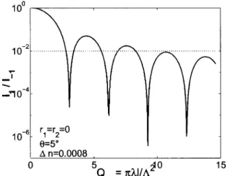
In simple gratings the Bragg regime is usually associated with thick grating diffraction, meaning that there is a single diffracted beam,3 whereas the Raman–Nath re-gime is understood as thin grating diffraction or the pres-ence of multiple diffracted orders.4 The two diffraction regimes are distinguished by use of the dimensionless pa-rameter Q⫽ 2l/⌳2, where Q⬍ 1 for the Raman–
Nath regime and Q⬎ 10 for the Bragg regime, although it is sometimes said7 that the Bragg regime starts when
Q ⬎ 1 or that, on the contrary, even for Q ⬎ 10 the
higher-order diffracted waves can be of considerable im-portance in gratings with large index modulation5 (⌬n ⬃ 10⫺3– 10⫺1). It is therefore necessary to be extremely
precise about our own definition of the Bragg diffraction regime. We use here as a reference the criterion defined by Mallick8: if QM⫽ Q/2 ⫽ l/⌳2 is greater than 10
(or if l⬎ lM⫽ 10⌳2/), the relative intensity of higher
orders is less than 0.01. His calculation uses a constant diffracted amplitude per unit length, which cannot be ex-tended to the intracavity case. Therefore we investigate whether his criterion remains valid when we use our model and consider the simple Bragg sample a particular case of the intracavity device for which the reflection co-efficients of the mirrors are zero. It is therefore useful to recall his main results for comparison purposes. He ob-tained for a relative intensity of order 1
His Bragg criterion is based on the decrease of the maxima of the cardinal sine function, which permits defi-nition of an absolute thickness threshold.
The result of our calculation is shown in Fig. 3. The relative diffracted intensity of order 1 (I1/I⫺1) is plotted
versus QM for reflection coefficients equal to zero. Our
curve is also shaped approximately as a cardinal sine. It is independent of index modulation in the range 10⫺6 ⬍ ⌬n ⬍ 5 ⫻ 10⫺3. The agreement with the result of
Mallick is good in the whole range mentioned. The high-est value⌬n ⫽ 10⫺2that we have tested brings us to the limit of the validity of Q-type criteria, as the grating strength3  ⫽ ⌬nlm/ cos, sometimes called a
modu-lation parameter, must then be taken into account.5 The practical range of interest for the intracavity device is re-stricted to the cases when a bare grating would not give a high diffraction efficiency, that is to say, when  Ⰶ 1. This can mean a small index modulation or a limited thickness of the material, as for multiple quantum wells, which exhibit a low in spite of a high ⌬n.15,16 The limi-tation to small grating strengths therefore does not re-duce the scope of our study, and we can use Mallick’s for-mulation of the thickness criterion.
B. Intensity of Diffraction Orderⴚ1
The basic principle of our device is the choice of a resona-tor length such that order ⫺1 fulfills the Fabry–Perot resonance condition. Given, length lmis then a discrete
parameter that is related to Fabry–Perot interference or-der m in the following way:
2lmcos ⫽ m. (20)
We use m as a normalized length parameter, so our re-sults do not depend on the wavelength or the incidence angle. When r2⫽ 1 the whole diffracted intensity is
ex-tracted from the cavity on reflection, propagating perpen-dicular to the incident wave. In this way the diffracted energy is not shared between the transmitted and the re-flected beams, as would be the case in a symmetric Fabry–Perot cavity. Figure 4 shows the variation of dif-fraction efficiency (diffracted intensity normalized to inci-dent read intensity I⫺1/IR) versus interference order m
for two values of amplitude reflection coefficient r1of the
front mirror. The curve exhibits a maximum that is close to unity for which the whole intensity of the incident wave is transferred to the reflected diffracted wave. The corresponding optimum length
lopt⫽
0cos
⌬n arccos
冉
2r11⫹ r12
冊
is a decreasing function of r1and of index modulation⌬n.
We are especially interested in the range of sample lengths from 0 to lopt, where the order⫺1 diffracted
in-tensity increases by several orders of magnitude toward its maximum, as there is no point in growing thicker crys-tals to get into a range in which the diffraction efficiency decreases.
In what follows, we examine the change caused in the intensities of orders 1 and⫺2 by an asymmetric Fabry– Perot resonator with r2⫽ 1, which is where the
intracav-ity device gives the best result. As the diffracted inten-sity is then extracted only on reflection, as mentioned above, the bare grating reference is a grating with a to-tally reflecting rear mirror (r2⫽ 1), so the diffraction
properties can be directly comparable. It is interesting to note that, as far as the intensities of the diffracted beams are concerned, the bare grating with its rear mirror is ac-tually equivalent to a double-length sample.
C. Intensities of Diffraction Orders 1 andⴚ2
Order⫺2 is the mismatched result of diffraction of order ⫺1 on the grating. In a bare Bragg grating it must re-main small compared with order 1. It was therefore not taken into account in the Bragg criterion by Mallick. Our calculations extend this result to the intracavity case. In Fig. 5 the relative intensity I⫺2/I⫺1of order⫺2
is plotted versus interference order m for the bare grating (r1⫽ 0) and for an intracavity grating (r1⫽ 0.9). This
relative intensity is low and exhibits hardly any depen-dence on sample length or on reflection coefficient r1 of
the front mirror. It increases with index modulation but remains well below 10⫺2as long as⌬n ⬍ 10⫺2.
Diffrac-Fig. 3. Bragg criterion in a bare grating. Relative diffracted intensity I1/I⫺1of order 1 normalized to order⫺1 is plotted
ver-sus QM⫽l/⌳2. The reference level is plotted at 0.01 (dotted
line).
Fig. 4. Logarithmic plot of diffraction efficiency I⫺1/IRof order
⫺1 versus Fabry–Perot interference order m for two reflection coefficients values, r1⫽ 0.6 and r1⫽ 0.9.
tion order⫺2 can therefore be safely ignored in the deri-vation of the thickness threshold to the Bragg diffraction regime.
Order 1, like order⫺1, is coupled to the incident wave. The only difference between them lies in the phase-matching condition, as order⫺1 is phase matched to the incident wave and order 1 is not. Figure 6 shows the variation of the order 1 diffraction efficiency versus m for a bare grating (r1⫽ 0) and for an intracavity grating
(r1⫽ 0.9). The diffraction efficiency of the bare grating
is an oscillating function of l; the envelope of its maxima remains almost constant. The diffraction efficiency of in-tracavity order 1 seems to be flat compared with that of the bare grating, except for sharp peaks that correspond to the minima of the diffraction efficiency of bare grating order 1. These peaks are double-resonance peaks, as we show in Section 4 below. Anyway, it is obvious that the order 1 diffraction mode is globally attenuated by the Fabry–Perot resonator, except for its sharp maxima that nevertheless do not exceed the maxima of order 1 for a simple Bragg grating. We can therefore use Bragg order 1 as an overestimation of intracavity order 1 to define our intracavity criterion.
This preliminary study of higher-order intensities has restricted our field of investigation to the relative inten-sity I1/I⫺1 of order 1 to find out the threshold thickness
from which higher-order intensities become negligible relative to that of the main diffraction order.
D. Intracavity Bragg Criterion
The variation of relative intensity I1/I⫺1is plotted versus
m in Fig. 7. From our study of order 1, we know that the
rapidly decreasing ratio (order 1/order⫺1) is due mainly to the increasing intensity of order⫺1, as the maxima of order 1 intensity do not decrease significantly. A new in-tracavity length criterion can then be established, assum-ing that the diffraction intensity of intracavity order 1 is equal to the bare sample’s intensity (I1FP⯝ I1bare), and if
only the variation of intracavity diffraction order ⫺1 is taken into account. To use Mallick’s results we need to compare the ratio of order 1 to the order⫺1 diffracted in-tensities of the intracavity grating and of the bare grat-ing. Order ⫺1 reflected diffracted intensity I⫺1FP for Fabry–Perot resonant length values lm can be expressed
analytically as a function of the bare sample diffracted in-tensity I⫺1barein the following way:
I⫺1 FP⫽
冋
共1 ⫺ r12兲 共1 ⫹ r12⫺ 2r1cos 2兲册
2 I⫺1 bare. (21)This expression can be developed for small values of to give, to lowest order,
I⫺1FP⫽
冋
共1 ⫹ r1兲共1 ⫺ r1兲
册
2I⫺1bare. (22)
The accuracy of the development in the whole range of length that we are interested in, that is, from 0 to lopt,
depends on the value of r1. For instance, the error is
less than 1% if r1⬎ 0.82.
From Mallick8 and taking into account that our bare sample reference with its rear mirror is equivalent to a double-length sample, we know that
if l ⬎lM 2 , then I1bare I⫺1 bare ⬍ 0.01. (23)
Fig. 6. Logarithmic plot of order 1 diffraction efficiency I1/IR versus interference order m for a bare grating (r1⫽ 0) and for
an intracavity grating (r1⫽ 0.9).
Fig. 5. Logarithmic plot of relative intensity I⫺2/I⫺1of order⫺2 normalized to order ⫺1 versus interference order m for a bare grating (r1⫽ 0) and for an intracavity grating (r1⫽ 0.9).
Fig. 7. Logarithmic plot of relative intensity I1/I⫺1 versus
in-terference order m for a bare grating (r1⫽ 0) and for an intrac-avity grating (r1⫽ 0.9).
For Eq. (22) and with I1FP replaced by its overestima-tion I1bare, if l⬎ lM 2 , then I1FP I⫺1 FP ⬍ 0.01
冋
共1 ⫺ r1兲 共1 ⫹ r1兲册
2 . (24) To find the new length threshold lFPfrom which thera-tio I1FP/I⫺1FPis smaller than 1% we use the l dependence
of I⫺1
FP. When we develop I⫺1bare⫽ sin
2(2) to lowest
or-der, the l dependence of I⫺1FP and hence of the ratio
I⫺1FP/I1FPappear to be purely quadratic, and, using
Mal-lick’s criterion, if l⬎ lM 2 共1 ⫺ r1兲 共1 ⫹ r1兲 ⫽ lFP, then I1FP/I⫺1FP⬍ 0.01. (25) The lowest-order development of I⫺1FPcan also be related to the sample length at Fabry–Perot resonance lm and
compared to the development of the transmitted intensity diffracted by a sample with no mirror at all, I⫺1nomir, to in-troduce an effective interaction length10that is due to the
Fabry–Perot cavity: I⫺1 nomir⬃  2⫽
冉
⌬nlm cos冊
2 , (26) I⫺1 FP⬃冋
共1 ⫹ r1兲 共1 ⫺ r1兲册
2 共2兲2 ⫽冋
共1 ⫹ r1兲 共1 ⫺ r1兲册
2冉
2⌬nlm cos冊
2 ⫽冉
⌬nleff cos冊
2 , leff⫽ 2共1 ⫹ r1兲 共1 ⫺ r1兲 lm. (27)To compare the intracavity Bragg criterion [inequality (25)] to the bare grating criterion [inequality (23)], we plot in Fig. 8 the relative intensity of order 1 versus the modi-fied Q parameter: QFP⫽ 关(1 ⫹ r1)/(1⫺ r1)兴2QM for
three values of the front mirror’s reflectivity. It can be seen that the validity of our criterion is independent of r1
and thus is quite general.
The Fabry–Perot resonator permits sharp attenuation of diffraction order 1 relative to length. As expected, ow-ing to the increase of the effective interaction length, the critical length from which all diffracted energy can be considered to be concentrated in one diffracted beam is duced further by the presence of the cavity when the re-flection coefficient is large.
A numerical example of a specific sample is now given to illustrate this new criterion. We consider a grating in semi-insulating multiple quantum wells.15 The grating’s thickness of 1m, grating period ⌳ ⫽ 2.4 m, read wave-length 0⫽ 840 nm, and refractive index n0⫽ 3.6 give
QM⫽ 0.12, clearly corresponding to a Raman–Nath
dif-fraction regime. The threshold thickness for the bare sample is lM⯝ 78m. Although the index modulation
is very large (10⫺3), the diffraction efficiency is only of the order of 10⫺5 because the sample is thin and because there are multiple diffraction beams. In an asymmetric Fabry–Perot cavity with r1⫽ 0.9 and r2⫽ 1 we get,
us-ing inequality (25), lFP⯝ 2m, which brings the
thresh-old down to a realistic value, even for multiple quantum wells. For the 1-m-thick sample of Ref. 12 we get QFP
⫽ 4.8, and we can see from Fig. 8 that the order 1 rela-tive intensity has decreased to 5 ⫻ 10⫺2. The diffraction efficiency can be calculated from Eq. (22), and we obtain 14%. Absorption has not been taken into account in this derivation, although we know it can be quite large in quantum wells and would certainly reduce the diffraction efficiency of the main order. An adequate Fabry–Perot resonator nevertheless contributes to a substantial reduc-tion of high-order diffracreduc-tion and can bring thin samples into a Bragg diffraction regime.
4. DOUBLE RESONANCE
A reasonable idea about the effect of the Fabry–Perot cav-ity on orders 1 and⫺2 diffracted intensities is that they should be attenuated, except when they are in resonance with the Fabry–Perot cavity modes. The curves plotted in Figs. 5 and 6 confirm this guess. The attenuation of order 1 intensity increases with the resonator length, ex-cept for sharp peaks, which coincide with the minima of a simple Bragg grating that must be interpreted. It is therefore important to investigate whether orders 1 and ⫺2 can be Fabry–Perot resonant simultaneously with or-der ⫺1. We refer to this situation as double resonance, although it is actually quadruple resonance, as it con-cerns the read beam, order ⫺1, order 1, and order ⫺2 (cos ⫽ cos ⫺1 and cos⫺2⫽ cos1). We show in this
section how double resonance can give rise to quenching or enhancement of the diffraction efficiency of order 1, de-pending on the sample length.
Three relations must be fulfilled simultaneously for double resonance to take place at a given length:
sin1⫽ 3 sin (28)
from the Raman–Nath relation,
Fig. 8. Logarithmic plot of relative intensity I1/I⫺1 versus modified Q parameter QFP⫽ 关2(1 ⫹ r1)/(1⫺ r1)兴QM for three
reflection coefficient values (r1⫽ 0.9, r1⫽ 0.5 and r1⫽ 0, the
2lDRcos ⫽ m 共m an integer兲 (29)
for the Fabry–Perot resonance condition for the read and ⫺1 diffraction order beams, and
2lDRcos1⫽ 共m ⫺ ⌬m兲
共⌬m an integer and ⌬m ⬍ m兲 (30) for the Fabry–Perot resonance condition for the 1 and⫺2 diffraction order beams.
It is clear that not all integer values of m can be com-patible with Eqs. (28)–(30), and we finally obtain
cosDR⫽
冉
1 ⫹ ⌬m 4m ⫺ ⌬m2 8m2冊
⫺ 1/2 . (31)In Fig. 9, angleDRis plotted as a function of the
ratio-nal number q⫽ ⌬m/m with 0 ⬍ q ⬍ 1. The angle in-creases steadily with q, showing a correspondence be-tween the two parameters in the whole range of angles where order 1 exists: for every angle, one ratio (⌬m/m) and hence at least one couple (m, ⌬m) can be found. Double resonance of order 1 and order⫺1 is then possible for at least one Fabry–Perot length and all its multiples. It is important to note that the condition for double Fabry–Perot resonance implies that the phase mismatch between the read beam and the order 1 diffraction beam is an integer number of : ⌬klDR⫽ ⌬m. We find
therefore that intracavity enhancement of order 1 is neu-tralized because the diffracted intensity that corresponds to this length is weak. The amazing fact that we need to explain is that the double-resonance peaks of the order 1 diffraction efficiency become maxima for the higher val-ues of m. Figure 10(a) is a linear plot of the order 1 dif-fraction efficiency, and Fig. 10(b) is a linear plot of the or-der⫺1 diffraction efficiency, both relative to interference order m. The juxtaposition of the two curves shows that the double resonance gives rise to minima of order 1 in-tensity in the range of resonator length where order⫺1 is increasing and to maxima in the range where order⫺1 is decreasing. We can compare the analytical expression obtained for the amplitude of order 1 by the successive
ap-proximation method (see Subsection 2.C) with that of the amplitude of the main diffraction order and its derivative relative to ⫽ ⌬nl/0:
SB1共0兲 ⬀
再
⫺rF⫹sin共2兲 ⫹ ⌬k关cos共2兲 ⫺ r1兴
共1 ⫹ r12⫺ 2r1cos 2兲
⫺ ⌬k exp共2ikl cos1兲 1 ⫺ r1exp共2ikl cos1兲
冎
, (32)
where rF⫹⫽ i⌬n/0cos and
SB⫺1共0兲 ⬀ sin共2兲 共1 ⫹ r12⫺ 2r1cos 2兲 , (33) dSB⫺1共0兲 d ⬀ cos共2兲共1 ⫹ r12兲/2 ⫺ r1 共1 ⫹ r12⫺ 2r1cos 2兲2 . (34)
The order 1 amplitude [relation (32)] is the sum of two terms. For the small values of considered in intracav-ity Bragg diffraction the first term is close to the deriva-tive of order⫺1 amplitude versus l, especially when r1
in-creases [relation (34)]. It should therefore change sign at
lopt. The second term gives rise to the double-resonance
peaks when Eq. (30) is fulfilled. Its resonant value is a decreasing function of lDR:
⌬m 共1 ⫺ r1兲lDR
. (35)
Fig. 9. Double-resonance intracavity refraction angleDR
ver-sus relative difference⌬m/m between the Fabry–Perot interfer-ence orders of diffraction orders 1 and⫺1.
Fig. 10. Linear plots of (a) order 1 diffraction efficiency I1/IR versus the interference order m and (b) order⫺1 diffraction effi-ciency I⫺1/IRversus interference order m.
The minima or maxima of the double resonance come from destructive or constructive interference between these two amplitude terms. A specific double-resonance length can hence be chosen to produce an extinction of or-der 1. A relative enhancement can also be obtained in the range of lengths where the main diffraction order is decreasing.
5. CONCLUSIONS
We have calculated the intensities of diffraction orders 1 and⫺2 of an intracavity grating. The intensity of order ⫺2 is negligible, and the intensity maximum of order 1 never exceeds those of the bare grating. We have there-fore been able to use Mallick’s criterion to calculate a new intracavity thickness threshold, lFP. When the effective
interaction length is increased, the intracavity setup of a diffraction grating can significantly reduce the thickness limit for the Bragg regime, where only one diffraction or-der is present. The reduction factor is an increasing function of r1 for an asymmetric Fabry-Perot cavity:
2(1⫹ r1)/(1 ⫺ r1). The Fabry–Perot resonance of the
diffraction order 1 gives rise to minima in the whole range of length from 0 to loptwhere the main diffraction order is
increasing, which definitely ensures that the Fabry–Perot grating device will widen the range of the Bragg diffrac-tion regime. The results of this study should prove use-ful in the design of intracavity Bragg devices by use of thin nonlinear media such as multiple quantum wells.
I. Zaquine’s e-mail address is [email protected].
REFERENCES
1. R. J. Collier, C. B. Burckhardt, and L. H. Lin, Optical
Ho-lography (Academic, Orlando, Fla., 1971).
2. Y. Ding, D. D. Nolte, M. R. Melloch, and A. M. Weiner,
‘‘Time-domain image processing using dynamic hologra-phy,’’ IEEE J. Sel. Top. Quantum Electron. 4, 332–341 (1998).
3. M. G. Moharam, T. K. Gaylord, and R. Magnusson, ‘‘Crite-ria for Bragg regime diffraction by phase gratings,’’ Opt. Commun. 32, 14–18 (1980).
4. M. G. Moharam, T. K. Gaylord, and R. Magnusson, ‘‘Crite-ria for Raman–Nath regime diffraction by phase gratings,’’ Opt. Commun. 32, 19–23 (1980).
5. R. Magnusson and T. K. Gaylord, ‘‘Analysis of multiwave diffraction of thick gratings,’’ J. Opt. Soc. Am. 67, 1165– 1170 (1977).
6. T. K. Gaylord and M. G. Moharam, ‘‘Thin and thick grat-ings: terminology clarification,’’ Appl. Opt. 20, 3271–3273 (1981).
7. A. Yariv and P. Yeh, Optical Waves in Crystals (Wiley, New York, 1984), Chap. 9, pp. 354–358.
8. S. Mallick, ‘‘Effets d’paisseur dans les reseaux,’’ presented at Ecole d’t d’Optolectronique Carge`se, France, summer 1990.
9. L. Menez, I. Zaquine, A. Maruani, and R. Frey, ‘‘Intracavity Bragg gratings,’’ J. Opt. Soc. Am. B 16, 1849–1855 (1999). 10. J. H. Collet, R. Buhleier, and J. O. White, ‘‘Enhanced
dif-fraction of light in GaAs microcavities,’’ J. Opt. Soc. Am. B 12, 2439–2444 (1995).
11. K. M. Kwolek, M. R. Melloch, D. D. Nolte, and G. A. Brost, ‘‘Photorefractive asymmetric Fabry–Perot quantum wells: transverse-field geometry,’’ Appl. Phys. Lett. 67, 736–738 (1995).
12. D. D. Nolte, K. M. Kwolek, C. Lenox, and B. Streetman, ‘‘Dynamic holography in a broad-area optically pumped ver-tical GaAs microcavity,’’ J. Opt. Soc. Am. B 18, 257–263 (2001).
13. L. A. Pipes, Applied Mathematics for Engineers and
Physi-cists (McGraw-Hill, New York, 1958), Chap. 4, pp. 101–102.
14. M. Born and E. Wolf, Principles of Optics (Pergamon, Lon-don, 1970), Chap. 12, pp. 604–607.
15. D. D. Nolte, D. H. Olson, G. E. Doran, W. H. Knox, and A. M. Glass, ‘‘Resonant photodiffractive effect in semi-insulating multiple quantum wells,’’ J. Opt. Soc. Am. B 7, 2217–2225 (1990).
16. Q. Wang, R. M. Brubaker, D. D. Nolte, and M. R. Melloch, ‘‘Photorefractive quantum wells: transverse Franz– Keldysh geometry,’’ J. Opt. Soc. Am. B 9, 1626–1641 (1992).