1INTRODUCTION
Many existing concrete structures are deteriorated and need to be replaced or rehabilitated. Deteriora-tions are often localized at the surface due to exposi-tion to severe weathering condiexposi-tions (de-icing salts and freeze-thaw cycles). Thin bonded concrete re-pair overlays are among promising rehabilitation ap-proaches to extend the service life of bridge desks. A number of debonding mechanisms have been devel-oped based on field observations and on mechanical considerations [Saiidi et al 90, Granju 96]. A litera-ture survey showed that debonding occurs only when a crack reaches the interface [Ong et al 95, Bernard 00, Granju 01]. In this case, the crack in-duces a specific state of disturbance at the interface. It means that the generated stress σy, perpendicular
to the interface, could exceed the tensile strength of the overlay material (new concrete layer) if tensile stress is above the tensile strength σbond. Conse-quently, debonding is initiated in tension perpendic-ular to the interface [Hilsdorf et al 92, Bi-jen et al 94]. Therefore, the tensile strength is
con-sidered as a critical design parameter and the tensile stress perpendicular to the interface controls the debonding mechanism. Initiated by tension stress, debonding propagation in mode I is due to a combi-nation of tension and shear stresses [Hils-dorf et al 92, Bijen et al 94, Granju 04]. There are two approaches to minimize the debonding risk. The first one is to minimize the magnitude of σy and it
will not described in this article. The second one is to develop a good adhesion. However, it is complex to define what a good interface is. There is no unique bond strength value above which debonding is not possible. Literature survey indicates that a bond strength ranging from 1,50 MPa
[Concrete Society 91, Granju 96] to 2,80 MPa [Sil-fwerbrand 90, Bernard 00] is recommended and seems to be sufficient to have a monolithic behavior. Nevertheless, others results indicates that relation the influence of the bond strength on debonding is systematic. It should be noted that in-situ tensile strength ranging between 1,30 and 2,09 MPa were measured on concrete beams without presenting any sign of debonding [Laurence 01]. But some results
Correlation between the roughness of the substrate surface and the
debonding risk
F.Perez, M. Morency, B.Bissonnette
Laval University, Québec, Canada Civil Engineering Department Email: [email protected]
L. Courard
University of Liège, Belgium
GEOMAC Department, University of Liège
ABSTRACT: This paper presents the influence of substrate surface preparation on the adhesion strength of repaired beams system. Bond between new and old concrete has been the subject of a number of investiga-tions, but in most cases, only adhesion strength was addressed. This parameter was used to estimate the dura-bility and/or the debonding risk for repaired structure and it’s a generally accepted auditing standards. Usual-ly, surface preparation of the substrate concrete is considered essential to achieve a durable repair because of its influence on the bond strength. To better understand debonding mechanism, in particular these related to surface preparation, roughness parameters were calculated to quantify the influence of surface preparation on the structural behaviour. Using this approach, repair beams prepared by way of four (4) concrete surface preparations were characterized. Results obtained show that repaired beams presenting a substrate with a rough surface permit to achieve a monolithic behaviour of the repaired system. Opposite structural behaviour, with large debonding, was recorded for those having smooth surface. However, all surface preparations used have promoted the same bond strength regardless the roughness of the substrate. The resulting analysis high-lights the relation between roughness parameter αrough and the debonding mechanism of repaired beams. Such
found in literature are in contradiction with this ap-proach, especially regarding the influence of the ten-sile strength of the interface. Debonding has been observed in the field even if bond strength was above the limit of 1,5MPa [Mellinger 63, Wheat 93, Lupien 95, Scapinato 96]. Event if, the relation roughness/bond strength isn’t yet established, the surface preparation has an impact on the behaviour of repaired structures. If the surface treatment in-duces a too flat roughness, debonding has been seen on overlay [Cusson et al 96, Wheat et al 93, Ong et al 95].
The adhesion, and consequently the durability of a repair, depends on various phenomenons taking place in the interfacial zone [Courard 99]: the wetta-bility of concrete substrate by the repair materials, concrete surface geometry, rheology of the repair concrete, roughness of the substrate surface, etc… The last one is often presented as the most important factor to achieve a good bond. This improvement is mainly assigned to the increase of the contact sur-face [Talbot et al 94, Santos et al 07]. But other re-sults suggested that roughness has no relevant effect on the bond strength [Silfwerbrand 90, Courard 99, Perez 05, Belair 06]. This misleading on the influence of roughness come from that roughness is often approached or evaluated with non effective method which give qualitative or not precise enough information.
Roughness is usually assessed only qualitatively; by visually observing the substrate surface and by classifying it from very smooth to very rough with rubber reference surfaces [ICRI Surface Preparation Guide 03732] Theses panels provide a simple tool for specifying and evaluating surface preparation, but, it still remains rather subjective. Nevertheless, these methods are unable to provide a sufficiently detailed representation of the actual surface profile for the calculation of morphological and statistical parameters. In order to achieve a reliable quantitative analysis of superficial concrete morphology after surface preparation, methods applied in other engineering sciences have been used in concrete field [Chiai et al 98, Courard 00, Maerz et al 01, Perez et al 03, Garbacz et al 05, San-tos et al 07]. The authors [Courard 99, Perez 05] recently implemented a system of this type based on Moiré interferometry and observation of the shadows produced by the roughness of the concrete substrate [Perez 05, Perez 07]. In all cases, the aim of these kinds of research was to adopt roughness parameters and correlate these with bond strength for design codes [Chiai et al 98, Courard 00, Maerz et al 01, Perez 05, Santos et al 07]. These
methods would help to estimate the real influence of roughness on bond strength and evaluate the durabil-ity of the repair system.
2EXPERIMENTAL WORK
The aim of the research is to better understand the mechanisms involved in the cracking behavior of bonded overlays used on reinforced concrete beams and slabs. The project involves the testing of real size reinforced concrete beams repaired with con-crete overlays using four different types of surface preparation and subjected to static flexural loading. The concrete beam specimens were simply support-ed with a point load at midspan. Structural capacity (evolution of the apparent rigidity, maximum deflec-tion, failure mode) and cracking behavior (flexural cracking and interface debonding) were monitored. 2.1General procedure
In this study, a systematic procedure was used to quantify surface roughness. The collected data were connected to the tensile bond strength and to the structural behavior of the repaired concrete beams. More details on the operating procedure are avail-able in Perez [Perez 07]. The substrates were cast following the method described below this part. When surface preparation completed, an optical pro-filometer was used to quantify the surface roughness and then, the beams were repaired with similar con-crete mixture. The beams were subjected to static loading test. Deflection and crack propagation were measured and record to evaluate the structural be-havior. After loading test, numerous cores and sam-ples taken from the repaired concrete beams were used to perform three types of (3) bond strength tests. Verifications made showed that in these col-lecting sections, the bond was not influenced by the mechanical loading. Then, an optical profilometer was used to quantify the surface roughness of the substrate interface break surface after the direct ten-sion test.
2.2Description of materials
A total of 25 beams was manufactured; five spec-imens for each of the four surface preparation tech-niques and five control specimens (not repaired). All the beams specimens were rectangular in cross-section 200 × 210 mm, and of length 1750 mm. The concrete mix design is given in table 1.
The specimens were made with ordinary Portland cement concrete (type I cement, 0,45 water to
ce-ment ratio, 6 % air content and nominal 45 MPa compressive strength, 5-20 mm coarse aggregate). The repairs were made with a micro-concrete (ag-gregate diameter less than 10 mm) with a lower wa-ter-cement ratio than the concrete used to cast the beams. Selection of repair mixture was based on rec-ommendation from the Québec DOT and also be-cause it is used as a reference material in many on-going research projects conducted at Université Laval in relation with repair and rehabilitation (type I cement, 0,40 water to cement ratio, 6 % air content and nominal 55 MPa compressive strength, 5-10 mm coarse aggregate).
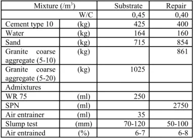
Table 1 : Mixtures proportions for base and re-pair materials
Mixture (/m3) Substrate Repair
W/C 0,45 0,40 Cement type 10 (kg) 425 400 Water (kg) 164 160 Sand (kg) 715 854 Granite coarse aggregate (5-10) (kg) 861 Granite coarse aggregate (5-20) (kg) 1025 Admixtures WR 75 (ml) 250 SPN (ml) 2750 Air entrainer (ml) 35 Slump test (mm) 70-120 50-100 Air entrained (%) 6-7 6-8 2.2.14 Surface Treatments
All preparations were done on a non-formworked surface. A detailed visual inspection of all prepared surfaces revealed the following macroscopic and visible effects for the different surface preparation methods:
• Scarification ( SCA ): It generally induces grooves in one direction (preferentially ori-ented macro-roughness), which the operator eliminated in this study by means of succes-sive transverse and perpendicular passes. • Sandblasting ( SAB ): It was done using grade
5 sand (1-1,4 mm) projected according to the TS-29. Sandblasting removes the surface lai-tance without inducing a high roughness. The sandblasting slightly exposed the aggregates (less than half of the diameter of the maxi-mum size aggregate).
• Chipping hammer followed by sandblasting ( PJ7S ): In this study, low weight
jackham-mer (7 kg) was used to minimize side-effects on substrate integrity. In addition, it should be stated that all surfaces prepared with a chipping hammer were followed by thorough sandblasting, a quite effective mean to
re-move dust and loose particles. The surface profile is characterized by large waves with high amplitudes.
• High-pressure water jetting ( WJ ): This sur-face preparation technique uses a high pres-sure water jet (in this case: 125 MPa prespres-sure and 27 L/h water flow). It induces a particu-lar texture characterized by particu-large waves, mostly parallel to the water flow.
2.3Roughness parameters
In Table 2, a summary of basic surface parame-ters is provided and more information about theses parameters is available in previous work [Perez 07, Courard 00]. These parameters are determined using the mean line as a reference. The mean line is deter-mined for any point of the actual profile by calculat-ing the Gaussian mean value derived from adjacent points. These parameters appear to be the most use-ful for concrete surface characterization
[Courard 00, Abu-Tair et al 00, Perez 05]. Table 2 : Profile statistical parameters
Pa-
ram-eter
Definition References
Ra Arithmetical mean deviation of the profile (mm)
DIN 4768/1, ANSI/
ASME B
46.1-1985 Sm
Mean spacing between profile peaks at the mean line, mea-sured over the assessment length (mm)
ISO 4768,
ANSI/ASME B 46.1-1985
Iss
Increasing of the specific sur-face. Ratio of projected surface under real surface (%)
CF Depth of the profile, excluding high peaks and holes (mm) ANSI/ASME B 46.1-1985
αrough Mean angle of the profile (de-gree) ANSI/ASME B 46.1-1985
All parameters are calculated in x and y direction. The val-ues presented in this article were the meaning of both direc-tion analyses. Generally, surface preparadirec-tions induced no isotropic roughness.
For instance, the arithmetical mean deviation of the profile (Ra) is used in the monitoring of
produc-tion processes where gradual changes in surface fin-ish due to cutting wear can occur. It is in fact the most common parameter referred in the literature to describe roughness [Silfwerbrand 90, Courard 99, Maerz et al 01, Perez 05]. Another useful surface analysis tool is the Abbott’s bearing ratio curve [Courard 99] a 1-D representation of the mean sur-face profile. The sursur-face parameters calculated from that curve provide information not only on local roughness, but also on the whole surface profile. CF
(bearing coefficient): the depth of the profile exclud-ing high peaks and deep valleys; it is evaluated from the vertical height of the Abbott’s curve approxi-mately linear segment, assumed here to extend from 20 % to 70 % in terms of bearing ratio values. The CF parameter gives an indication of the surface
flat-ness: the lower is the CF value, the flatter is the
pro-file. Finally, the parameter αrough is calculate by the
combination of CF and Sm as equation below shows: 1 4 tan ( F) rough m C S α = − × (2) The parameter αrough represents the angle between the
horizontal level and the mean profile of the surface. αrough is
included between 0 and 90 degree.
2.4Bond strength characterization
It exist many techniques to characterize the bond strength of a repair system. In this work, two (2) were used. A short description of each test is avail-able in the figure 1.
Usually, the quality of a repair system is evaluat-ed through a direct tension test. In field condition, a pull-off tester can be used to perform tensile bond test. This paper presents a more suitable direct ten-sile (DT) test that was used because of its lower variability (figure 1-a)). Correlation between pull-off test and direct tensile test has been done and is pre-sented in Perez [Perez 05]. In all cases, results indi-cate that mean value is similar with both tests. The bond strength in tension was done for the composite made from the four 4 surface preparation.
To measure the direct shear bond (DS), the same type of core is placed in a ‘guillotine’ apparatus (fig-ure 1-b). Due to limitation of the amplitude in the shear plan, only smooth interface can be tested with this setup. Based on this restriction, only shear strength for SAB and SCA has been evaluated. All tests were performed at least 7 month after casting of the substrates.
a) b)
Figure 1 : Description of the bonding test: a) the direct tension test and b) the direct shear test
2.5Debonding observations
The debonding observations were presented in previous works [Perez07]. A summary description of the procedure used to characterize and map the pattern of cracks is made below. Three (3) successive methods were used.
The initiation of all cracks was detected with the eye. After each crack occurrence, or after each cycle, the initiation and propagation of all cracks were marked carefully at the concrete surface, and the widths of few cracks were measured using a crack microscope with a resolution of 20 µm.
Then, LVDT is placed to measure the displacement of two points located on either side of the crack. Resolution of this LVDT is about 5 µm/m and the extension is ±800 µm. These captors were used to follow the width of a debonding crack or a vertical crack.
Cracks mapping consists of a picture of the transparency film shot with a digital camera and the colors removed with imaging software.
3RESULTS
3.1Surface topography characterization 3.1.1Before repaired operation
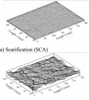
In accordance with the procedure described, four (4) optical profilometry measurements were per-formed before placing the repair material. The re-sults of two (2) profiles are presented in figure 2.
a) Scarification (SCA)
Figure 2 : Profiles obtained with different types for SCA and WJ surface preparation.
From the roughness parameters summarized in ta-ble 3, it can be seen that the Ra value is
approximate-ly ten (10) times greater for both HYD and JP7S than values obtained with SCA and SAB, which pro-duced a rather smooth surface. Abbott’s parameter (CF) gives consistent representations of the influence
of surface treatment on roughness. As shown in ta-ble 3, SCA surface is two (2) time flatter than SAB. All parameters pointed out the fact that HYD and JP7S induce two (2) very similar roughness. SCA gave the smoother surface with a profile comparable to a formworked surface. SAB induced a typical sur-face in which roughness is produced by the aggre-gate. Water jetting (HYD) and Pneumatic jackham-mer (PJ7S) induced a much rougher profile than scarification (SCA) and sandblasting (SAB). All pa-rameters indicated clearly that roughness is higher when energy invested in the surface preparation was.
Table 3 : Roughness parameters for the 4 sur-faces preparation
Roughness
Parameters SCA SAB PJ7S WJ
Under substrate Ra (mm) 0,24 0,46 2,64 2,25 Sm (mm) 9,40 9,50 44,00 31,00 αroughness (degree) 5,9 10,9 13,4 16,2 Iss (%) 1,023 1,093 1,126 1,287 CF (mm) 0,41 0,87 4,71 4,30
After tensile test
αroughness (degree) 4,3 8,5 11,8 12,5
3.1.2After repaired operation
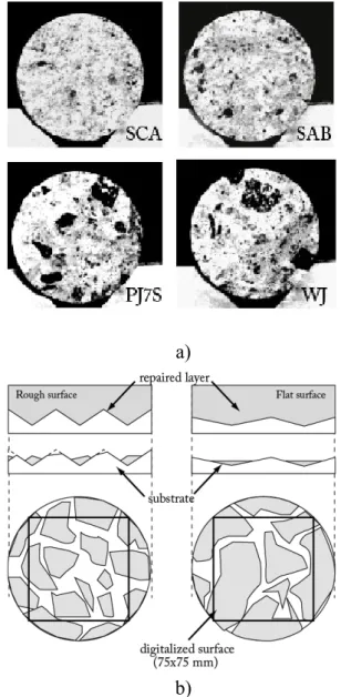
Optical profilometry measurements were per-formed under the substrate section after the tensile test. The maps of ruptured surface were made under sample tested in tension as show in the figure 3-a). The surface digitalized was about 75 × 75 mm. A detailed visual inspection of all specimens’ surfaces revealed the following macroscopic and visible ef-fects for the different surface preparation methods: There were more aggregates ruptured for WJ and MP7S than for SAB. No aggregates ruptured for SCA were observed (big aggregates are black in the picture on the figure 3-a). As depicted in the fig-ure 3-b), flatter was the surface preparation and flat-ter is the breaks surface. There was more repaired mortar at the breaks surface for initial flat surface than for rough surface figure 3-b).
a)
b)
Figure 3 : Surface ruptured after tensile test. 3.1.3Analysis
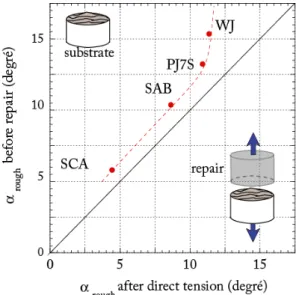
The objective of these two periods of measure was to evaluate the cracks pattern after rupture in comparison to the initial roughness of the substrate surface. Since the interface is the weakness link, the rupture should take place along this plan. The obser-vation of the failure mode was instructive to the comprehension of the adhesion mechanism. As re-sults showed, the breaks surface did not correspond-ed systematically with the initial substrate surface. When the roughness went up a certain level, the break surface was not influence by the initial ness. The analysis of the surfaces with two rough-ness parameter, αrough , illustrated in figure 4, this
effect. When substrate roughness is higher than αrough
= 10 degree , the pattern of cracking is similar regardless the initial roughness. In this condition, the propagation of the cracks did not follow the interface zone and monolithic rupture occurred.
Figure 4 : Comparison of the surface of the substrate and the break surface after a direct tensile test by means of the parameters αrough.
3.2Adhesion Evaluation
Thirty-four (34) cores and five (5) rectangular wedge splitting specimens were used to characterize the influence of the surface preparation on the bond strength. Table 4 presents the results of the mechani-cal properties of the interface for both tensile and shear test as a function of the surface preparation. As shown in previous studies [Silfwerbrand 86, Tal-bot et al 94, Courard 05], bond strength depend on the method used to promote roughness of the sub-strate surface. Previous works has show that the jack-hammer preparation technique is potentially harmful for the concrete substrate superficial layer [Talbot et al 94, Belair 06]. Some significant crack-ing is induced, and it is likely to reduce bond/adhe-sion between the repair material and the old concrete as shows in table 4
Adhesion strength
For all surfaces, bond strengths were very good compared to those typically obtained in field and the results are above the recommended threshold value of 1,5 MPa. As table 4 indicates, excepted for PJ7S, for which there are little difference between the bond obtained with the three (3) others methods (SCA, SAB and HYD). The results were therefore analyzed using a statistical test based on Student-Fishers’ law. It shows that the type of surface prepa-ration does not have a significant influence on adhe-sion strength. As explained before, the jack-ham-mered surface provided the lowest bond strength
[Courard et al 05].
Shear strength
The direct shear test results were analyzed with the same statistical approach. Results shown that the surface preparation does not have a significant influ-ence on the shear bond strength. The shear strengths are 2 times bigger than adhesion strengths. As noted, the tensile strength of the bond is generally consid-ered to be half of its shear strength [Sancier 90, Granju 96, Chausson et al 98, Momayez et al 05]. In this case, the ratio is about 0,42 for SCA surfaces and 0,45 for SAB surface.
Table 4 : Mechanical properties of the interface
DT DS
Surface treatment Mean value
(MPa) Nb Mean value (MPa) Nb SCA 2,60 5 5,77 5 SAB 2,42 9 5,87 5 PJ7S 1,81 6 - -WJ 2,71 4 - -Substrate 3,26* Repair 3.20*
DT :Direct tension test , DS : Direct shear test
* estimation with method developed by Rossi [Rossi
et al 96]
4ANALYSIS
4.1Relation bond strength and roughness
The relation between surface roughness and bond strength is plotted in figure 5. Many roughness pa-rameters were used to test this relation, but only one was plot. It’s the comparison of tensile strength and Ra. As stated, this parameter Ra is the most
common-ly used in literature. But, comparable conclusions could be made using others parameters
[Perez et al 08].
In first approximation, it seems that there is no lationship between roughness and adhesion. The re-sults confirmed those obtained by Belair [Be-lair 2006]. Previous studies [Courard 99, Gar-bacz et al 05] have showed that at microscopic level roughness induced by the different surface prepara-tions are very similar. An in-depth analysis of the microscopic roughness was made for the four (4) surface preparations [Perez et al 05] and the results confirmed that there is no significant difference on the microscopic roughness from a statistical stand-point. In fact, bond is more likely to be influenced by micro-roughness than macro-roughness [Courard 99, Garbacz et al 05]. But, in this analyse, rupture was considered to occur at the interface. However, as showed before, for rougher surface, the break
sur-face doesn’t follow the physical intersur-face. As indi-cated in figure 3, the breaks surface correspond to the interface surface only for flatter surface as SCA and SAB were. In the case of WJ and PJ7S, cracks propagation swing around the interface. In this con-dition, the results presented in figure 4 have no sig-nification. Consequently, it’s impossible to conclude about the relation between roughness and adhesion with this data.
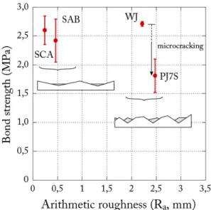
4.2Relation between debonding and bond strength In regard to the debonding mechanism, the design of bonded concrete repair must take account of on the tensile stress perpendicular to the interface. This tensile debonding stress results of many effects like the flexural stiffness of the bending layer or the peeling effects [Granju 01]. Debonding initiates when the tensile stress at the interface exceeds the bond strength. So, it is impossible to observe a debonding until stress stays under the bond strength. This description highlights the prevalence of the tensile strength on the existence and the propagation of debonding. So the test which validates the quality of the execution of a repair is a test which makes it possible to characterize the tensile strength of the composite.
Figure 5 : Relation between adhesion and the roughness parameters Ra
Figure 6 presents the length of debonding measured during loading tests in function of the adhesion evaluation. The debonding obtained on SCA-beams indicate that an adherence of 2,60 MPa does not guarantee the monolithic behaviour whereas an adherence of 1,80MPa (R-JP7S) seems to be sufficient. This debonding has modified the structural behaviour of these repaired SCA-beams. This result lets suppose that an inconsistency was appeared.
Adhesion appeared to be a non sufficient parameter to prevent debonding. Of course, a monolithic behaviour is impossible to achieve without a minimum of adhesion. But it’s not enough. Whereas JP7S-beams have a much lower adhesion than SCA-beams, there was no debonding during structural tests.
Figure 6 : Relation between adhesion and the debonding length
In the other side, SCA-beams configuration exhibited very high debonding with a much higher bonding strength. Finally, SCA-beams and SAB-beams have the same bond strength and their structural behaviours were dissimilar. Theses differences can’t be explained by the variation of the bond strength.
4.3Relation between debonding and roughness
In fact, the relation between reduction of debonding risk and bonding strength came from a misunderstood. In literature [Silfwerbrand 90, Bernard 00], good bonding strength has been reported when a high roughness surface was produced by the surface preparation technique. In this case, no debonding was observed [Silfwer-brand 90, Bernard 00]. So, the appropriate structural behaviour has been often related to the good adhesion instead of roughness. Results below indicated that this assumption could not be sufficient.
Figure 7 present the length of debonding measured during loading tests in function of the roughness evaluation. It exists a roughness threshold above which the risk of debonding is reduced. In the configuration of this program, this threshold of αrough,
is equal to 8degree, which correspond to the SAB preparation of surface. For the practical point of
view, the roughness threshold should be estimated from the initial roughness, directly after the surface preparation.
Figure 7 : Relation between debonding length and the roughness parameters αrough
As Figure 7 showed, there is a shift in the αrough,
between the estimation made before repair operation and after the tensile test. Explanations about this shift have been given previously on this subject. Regard to this, the threshold is about 11,8degree for αrough. In addition, these values are not universal
values. The stresses at the interface are a function of the flexural rigidity and of the thickness of the repair layer. For other beam geometry, the threshold could be different. But the concept will be the same. To obtain a monolithic structural behaviour, the surface roughness must exceed a certain threshold.
4.4PROPOSED APPROACH FOR DESIGN DURABLE REHABILITATION
4.4.1Modification of the debonding mechanism As noticed previously, in regard to the debonding mechanism, the design of bonded concrete repair is made by taking account of the tensile stress perpendicular to the interface. Debonding initiates when the tensile stress at the interface exceeds the bond strength. But results obtained in this work indicated that debonding can occurs regardless the bond strength. Therefore, this parameter couldn’t be use as a parameter to guaranty the repaired structure’s durability. However, based on mechanical measurement, it was demonstrated that the interfacial surface is zone of less strength than bulk concrete. Then, it could be proposed that a local debonding always occurs in this weakness zone but its propagation is stopped rapidly. As noticed, the propagation is evaluated by the GF value. In [Perez 05], based on experimental measurements, a
strong relation has been highlighted between the parameter αrough and the energy GF. This relation was
in correspondence with other literature results
[Büyüköztürk 98]. A propagation mechanism is proposed to take account of all theses new information.
5CONCLUSIONS
The aim of the research was to better understand the mechanisms involved in the cracking behaviour of bonded overlays used on reinforced concrete beams. This works have focus on the influence of the surface preparation.
Through a variety of measurements on substrate surfaces and on concrete to concrete break surfaces with the non-contact method, the roughness of surface and of the fracture surface have been investigated. A complete evaluation of the bond developed between repair material and substrate has been made. Experimental study, as presented in this paper, emphasizes the influence of surface roughness on the structural behavior of repaired beams and on the debonding mechanism. Although tensile bond has been proposed by many investigators as a tool to evaluate the structural behavior of repaired beams, it is, regard to results obtained, that this parameter alone is not sufficient enough to assess the monolithic behavior, especially for cases of relative flat surface preparation. Results indicate that increase the roughness does not enhance the bond strength. The result of the characterization and image analysis of fracture pattern, roughness parameters and binary image stacks are essential geometric and morphological information required in a mechanical model of fracture. The modification of the debonding model proposed to use the angle αrough as parameter to
control the interface debonding. The local angle αrough along the crack progression is determined from
the topography analysis. Then, to insure monolithic behaviour, surface treatment must produce a minimal adhesion and must induce a certain level of roughness. While the roughness is higher than a certain threshold, the debonding risk decrease rapidly and monolithic behaviour is reached. By taking the roughness angle αrough as design parameter
for repaired structure, it makes possible to evaluate the potential durability of structure even before the casting of the repair material. In opposite, the evaluation of the bond strength can only be done when the concrete has reached a certain level of maturity. Then, if the repaired proves to be inadequate, the only exit resides in to the destruction
of the superficial layer of repair material. This step generates expansive socials and economics costs.
6REFERENCES
Abu-Tair A.I., Lavery D., Nadjai A., Rigden S.R., Ahmed T.M.A. (2000), A new method for evaluating the surface roughness of concrete cut for repair or strengthening, Construction and Building Materials, 14, pp 171-176
Bernard O., (2000), Comportement à long terme d’éléments de structures formées de bétons d’âges différents. PhD thesis, EPFL.
Belair N.Jr, (2006), Contribution à la mise au point d’une
procé-dure de caractérisation quantitative des surfaces en béton en vue de travaux de réfection M.Sc. Thesis, Sciences and Engi-neering Faculty, Université Laval, Québec, Canada, CRIB. Bijen J. and Salet T., (1994), Adherence of young concrete to old concrete development of tools for engineering. In Proceed-ing of 2nd Bolomey Worshop on Adherence of Young on Old Concrete., pages 1–24. Wittman, F.W..
Büyüköztürk O. and Hearing B. (1998) crack propagation in concrete composites influenced by interface fracture parameters, In. J Solids Structures Vol. 35, N 31, pp. 4055-4066
Chausson H., (1998), Pratique des réhabilitations en mortier projeté renforcé de fibraflex - 10 ans d’acquis. In 3ième Col-loque International Francophone sur Les Bétons Renforcés de Fibres Métalliques, St Foy, Québec.
Chiai B., Van Mier J.G.M. and Vervuurt A., (1998), Crack growth mechanisms in four different concretes: microscopic observations and fractal analysis, Cement and concrete research, v28,n1,pp103.114
Concrete Society (The U.K.) (1991). ‘Patch repair of reinforced concrete. Model specification and method of measurement’. Concrete Society Technical Report No. 38. Courard L., (1999), Contribution à l'analyse des paramètres in-fluençant la création de l'interface entre un béton et un système de réparation. Appétence et adhérence: cause et effet d'une liai-son”. PhD thesis, Université de Liège, Collection des Publica-tions de la Faculté des Sciences Appliquées, No. 192, 213 pp. Courard, L., (2000). Parametric Study for the Creation of the Interface between Concrete and Repairs Products. Mater. Struct., 33 (225) 65-72.
Courard, L, Bissonnette B. and Belair N.Jr, (2005). Effect of
surface preparation techniques on the cohesion of superficial concrete: Comparison of jack-hammering and water jetting, In: ICCRRR 2005 International Conference on Concrete Repair, Rehabilitation and Retrofitting (Eds. H. Beushausen, F. Dehn and M.G. Alexander), Cape Town, South Africa (Nov.21-23). Cusson D. and Mailvaganam N., (1996), Durability of repair
materials. Concrete international, pages 34–38, march.
Denarié. E.(2000), Etude expérimentale des couplages vis-coelastique – Croissance des fissures dans les bétons de ciment. PhD thesis, EPFL.
Friebrich M.H., (1993) Influence of the surface rougghness on the adhesion between concrete and gunite mortars overlays. Proceeding of 2nd Bolomey worshop on adherence of young on old concrete., pages 107–114
Garbacz A, Górka M and Courard L., (2005), On the effect of concrete surface treatment on adhesion in repair systems. Mag Concr Res, 57:49–60.
Granju J.L., (1996), Fibre reinforced thin concrete overlays : The mechanism of their debonding in relation with their crack-ing. Concrete Repair, Rehabilitation and Protection, pages 583–590.
Granju J.L., (2001), Debonding of thin cement-based overlays. journal of materials in civil engineering, pages 114–120, March-April.
Granju J.L., Sabathier V., Turatsinze A, Toumi T, (2004), In-terface between an old concrete and a bonded overlay: debond-ing mechanism, Interface Science, vol. 12, pp 381-388.
Wheat D.I., Fowler D.W. and Al-Negheimish A.I., (1993), Thermal and fatigue behavior of polymer concrete overlaid beams. journal of materials in civil engineering, pages 110– 118.
Hilsdorf H.K., Gunter M. and Haardt P., (1992), Fracture me-chanics application in the analysis of concrete repair and pro-tection systems. Fracture Mechanics of concrete Structures, pages 951–959.
Laurence O., (2001), La fissuration due au retrait restreint dans les réparations minces en béton : apport combiné de l’expéri-ence et de la modélisation. PhD thesis, Université Laval, CRIB, Canada.
Lupien C., Chanvillard G., Aïtcin P.-C., and Gagné. (1995). Réhabilitation d’une chaussée par resurfaçage mince adhérent en béton renforcé de fibres d’acier. pages 246–250. ASCE. Maerz H., Nanni A., J.Myers J. and Galecki Greg (2001). Laser profilometry for concrete substrate characterization prior to FRP laminate application. Concrete Repair bulletin. May-June, pp 4-8.
Mellinger F.M., (1963), Structural design of concrete overlays. ACI journal, 60(2) :225–237, 1963.
Momayez A., Ehmasi M.R., Ramezanianpour A.A. and Rajaie H. (2005), Comparison of methods for evaluating bond strength between concrete substrate and repair materials, Ce-ment and Concrete Research, 35, 748-757.
Ong K.C.C., Paramasivam P., Ong B.G. and Lee S.L., (1995),. Probabilistic approach to fatigue life prediction of repaired re-inforced concrete slabs. ACI Structural journal, 92(5).
Perez F., Bissonnette B. and Courard L., (2003), Outils de car-actérisation paramétrique de la rugosité des surfaces en béton: nouveaux développements. Journées scientifiques du RF²B, 25-26 August, Sherbrooke, Canada, 10p.
Perez F., Courard L., Bissonnette B., Garbacz A. and Gorka M., (2005), Comparison of two different techniques for the evaluation of concrete surface roughness. In: ICCRRR 2005 International Conference on Concrete Repair, Rehabilitation and Retrofitting (Eds. H. Beushausen, F. Dehn and M.G. Alexander), Cape Town, South Africa (Nov.21-23).
Perez F., (2005), Contribution à l’étude du comportement mé-canique des éléments bi-couches composés de bétons d’âges différents sous sollicitations statiques et dynamiques. Ph.D. Thesis, Sciences and Engineering Faculty, Université Laval, Québec, Canada, CRIB.
Perez F., Bissonnette B. and Gagné R., (2007), Parameters af-fecting the cracking behavior of bonded overlays used on rein-forced concrete slab subjected to flexural loading,
Saiidi M., Vrontinos S, and Douglas B., (1990), Model for the response of reinforced concrete beams strengthened by con-crete overlays, ACI structural Journal, v87, n6, pp687-695. Rossi, P., Ulm, F.-J., Hachi, F., (1996), "Compressive be-haviour of concrete: physical mechanisms and modeling", Journal of Engineering Mechanics, ASCE, vol. 122, n°11, pp. 1038-1043
Santos P.M.D., Jùlio E.N.B.S., Silva V.D., (2007), Correlation between concrete-to-concrete bond strength and the roughness of the substrate surface, Construction and Building Materials 21 1688–1695
Saucier.F., (1990) La Durabilité de L’adhérence Des Répara-tions En Béton. Ph.D. Thesis, Sciences and Engineering Facul-ty, Université Laval, Québec, Canada, CRIB.
Scapinato E.J., (1996), Thin polymer concrete bridge deck overlays. Concrete construction.
Silfwerbrand J., (1990), Improving concrete bond in repaired bridge decks. Concrete International, September: 61–66. Talbot C., Pigeon M., Beaupré D., and Morgan D.R., (1994), Influence of surface preparation on long-term bonding of shotcrete. ACI Materials Journal, November-December :560– 566.