HAL Id: hal-01008566
https://hal.archives-ouvertes.fr/hal-01008566
Submitted on 22 May 2018
HAL is a multi-disciplinary open access
archive for the deposit and dissemination of sci-entific research documents, whether they are pub-lished or not. The documents may come from teaching and research institutions in France or abroad, or from public or private research centers.
L’archive ouverte pluridisciplinaire HAL, est destinée au dépôt et à la diffusion de documents scientifiques de niveau recherche, publiés ou non, émanant des établissements d’enseignement et de recherche français ou étrangers, des laboratoires publics ou privés.
Numerical Simulation of Spin Coating Processes
Involving Carbon Nanotube Suspensions
Elías Cueto, Anson Ma, Francisco Chinesta, Malcolm Mackley
To cite this version:
Elías Cueto, Anson Ma, Francisco Chinesta, Malcolm Mackley. Numerical Simulation of Spin Coating Processes Involving Carbon Nanotube Suspensions. International Rheology Meeting, 2008, Chatel, France. �hal-01008566�
Numerical simulation of spin coating processes with carbon nanotubes
suspensions
E. Cueto
1, A. Ma
2, F. Chinesta
3, M. R. Mackley
21
Group of Structural Mechanics and Material Modelling. Aragon Institute of Engineering Research, I3A.
Universidad de Zaragoza, Spain
URL: http://gemm.unizar.es e-mail: [email protected];
2
Department of Chemical Engineering, U. of Cambridge. New Museums Site, Pembroke Street.
Cambridge, CB2 3RA, U.K.
URL: http://www.cheng.cam.ac.uk/research/groups/polymer/ e-mail: [email protected]
3
Laboratoire de Mecanique des Systemes et des Procedes UMR 8106 CNRS-ENSAM-ESEM. Paris, France.
URL: http://www.paris.ensam.fr/lmsp/ e-mail: [email protected] ABSTRACT: In this paper we address the problem of simulating the behaviour of Carbon nanotubes (CNTs) suspensions in spin coating processes. Spin coating is a procedure used to apply uniform thin films to flat substrates by means of a high rotating velocity and the subsequent centrifugal force.
In this work we assume a suspension of chemically treated CNTs, such that they do not aggregate. In such a suspension, CNTs can be treated as rigid fibres whose orientation is dictated by the flow of the solvent. In order to treat the associated free-surface problem and to avoid the numerical problems associated to their FE solution, we have implemented a Natural Element strategy in an updated Lagrangian framework.
The resulting model is thus composed by a description of the micro scale, related to the orientation of the carbon nanotubes and the assumption of a quadratic closure relation, together with the natural element approx-imation for the Navier-Stokes problem governing the macroscopic suspension kinematics.
KEYWORDS: Spin coating, carbon nanotubes, numerical simulation, meshless methods.
1 INTRODUCTION
Carbon nanotubes have generated a tremendous inter-est in the scientific community after their discovering by Iijima in 1991 [4]. A single-walled carbon nan-otube (SWNT) is a one-atom thick sheet of graphite (called graphene) rolled up into a seamless cylinder with diameter on the order of a nanometer. They posses impressive mechanical and electrical proper-ties:
• Young’s modulus: 1 to 5 TPa • Tensile Strength: 13-53 GPa • Elastic strain up to 5%. • Density 2160 kg/m3
.
This, together with their low price (in the order of
50$/kg) suggest their use as reinforcements in
com-posites. In addition, nanotube based transistors have been made that operate at room temperature and that are capable of digital switching using a single elec-tron. To this end, it is extremely important to know their behaviour in suspension. Although several stud-ies have focused on producing polymer nanotube composites, many practical challenges remain before their potential can be fully realized. Dispersing the nanotubes individually and uniformly into the ma-trix seems to be fundamental in producing composites with reproducible and optimal properties.
In this work we establish a method for the nu-merical simulation of carbon nanotubes suspensions forming processes. We focus our attention to spin coating processes, although we believe that the
tech-nique is general enough to be applied to other forming processes as well.
2 SPIN COATING PROCESSES
Spin coating is a procedure used to apply uniform thin films to flat substrates. In essence, an excess amount of a solution is placed on the substrate, which is then rotated at high speed in order to spread the fluid by centrifugal force, see Fig. 1.
Figure 1: An example of a spinning machine (Cf.
wikipedia.org)
The difficulties in the numerical simulation of spin coating processes arise from the tremendous deforma-tion of the domain, on one side (note that films of around30 − 50µm are produced after a drop of
liq-uid) and to the multiscale nature of the problem on the other.
The numerical strategy employed is composed by two main ingredient in order to cope with these diffi-culties. First, meshless methods (in particular, the nat-ural element method, NEM) were employed to avoid the remeshing efforts characteristic of FE simulations, which are linked, as is well known, with numerical diffusion on the results and subsequent loss of accu-racy.
In order to cope with the second difficulty men-tioned before, we have implemented a kinetic theory model to simulate the behaviour of the carbon nan-otubes in suspension. This model considers the car-bon nanotubes as rigid fibers and allows for the track-ing of their orientation durtrack-ing the process.
3 BASICS OF THE NATURAL ELEMENT METHOD
Consider a model composed by a cloud of points
N = {n1, n2, . . . , nm} ⊂ Rd, for which there is a
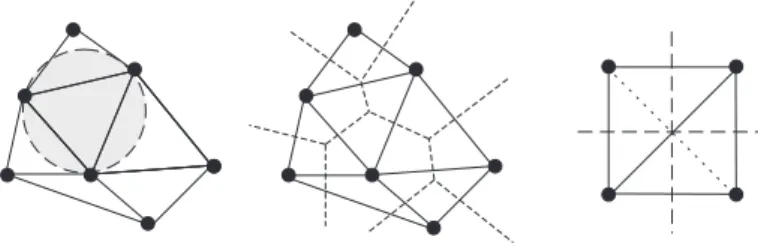
unique decomposition of the space into regions such that each point within these regions is closer to the node to which the region is associated than to any other in the cloud. This kind of space decomposition is called a Voronoi diagram (also Dirichlet tessella-tion) of the cloud of points and each Voronoi cell is formally defined as (see figure 2):
TI = {x ∈ Rd : d(x, xI) < d(x, xJ) ∀ J 6= I}, (1)
whered(·, ·) is the Euclidean distance function.
Figure 2: Delaunay triangulation and Voronoi diagram of a cloud of points.
The dual structure of the Voronoi diagram is the Delaunay triangulation, obtained by connecting nodes that share a common(d−1)-dimensional facet. While
the Voronoi structure is unique, the Delaunay triangu-lation is not, there being some so-called degenerate cases in which there are two or more possible Delau-nay triangulations (consider, for example, the case of triangulating a square in 2D, as depicted in Fig. 2 (right)). Another way to define the Delaunay trian-gulation of a set of nodes is by invoking the empty
circumcircle property, which means that no node of
the cloud lies within the circle covering a Delaunay triangle. Two nodes sharing a facet of their Voronoi cell are called natural neighbours and hence the name of the technique.
Equivalently, the second-order Voronoi diagram of the cloud is defined as
TIJ = {x ∈ Rd: d(x, xI) < d(x, xJ) < d(x, xK)
∀ J 6= I 6= K}. (2)
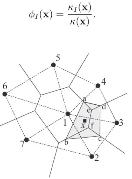
The most extended natural neighbour interpola-tion method is the Sibson interpolant [7] [8]. Con-sider the introduction of the point x in the cloud of
nodes. Due to this introduction, the Voronoi diagram will be altered, affecting the Voronoi cells of the nat-ural neighbours of x. Sibson [7] defined the natural
neighbour coordinates of a pointx with respect to one of its neighbours I as the ratio of the cell TI that is
transferred to Tx when adding x to the initial cloud
of points to the total volume ofTx. In other words, if
κ(x) and κI(x) are the Lebesgue measures of Tx and
TxI respectively, the natural neighbour coordinates of
x with respect to the node I is defined as φI(x) = κI(x) κ(x) . (3) x 1 2 3 4 5 6 7 a b c d e f
Figure 3: Definition of the Natural Neighbour coordinates of a point x.
In Fig. 3 the shape function associated to node 1 at pointx may be expressed as
φ1(x) =
Aabf e
Aabcd
. (4)
Sibson’s interpolation scheme possesses the usual reproducing properties for this class of problems, i.e., verifies the partition of unity property (constant con-sistency), linear consistency (and therefore are suit-able for the solution of second-order PDE). Other in-teresting properties such as the Kronecker delta prop-erty [9] and linear interpolation on the boundary [2] are also verified by the NEM. This is especially im-portant for problems involving friction or, in general, in which the compatibility along the boundary is im-portant.
This kind of interpolation scheme is then used in a Galerkin framework, exactly like in the finite element method. The advantages that this method provides, if compared to the Finite Element Method, is that no lack of accuracy is obtained due to mesh distortion
[1]. This allows us to employ an updated Lagrangian strategy for simulating the free surface flows arising in the problem, which notably simplifies the formu-lation and practical implementation of the code. For more details on the method, the interested reader can consult [5].
4 CONSTITUTIVE MODELLING
The flow model of carbon nanotubes (CNT) consid-ered as short fibers suspensions is defined by the fol-lowing equations (see [6] and references therein)
• The balance of momentum equations, where
we only consider, following [3], the centrifugal forces
Divσ = −ω × (ω × r) (5) where σ is the stress tensor and ω the rotating
speed of the machine.
• The incompressibility condition
Divv = 0 (6)
where v represents the velocity field.
• The constitutive equation, with a quadratic
clo-sure relation for the fourth order orientation ten-sor and other simplifying assumptions, results
σ = −pI + 2µ{D + NpTr(a D) a} (7)
where p denotes the pressure, I the unit
ten-sor, µ the equivalent suspension viscosity, D
the strain rate tensor,Np a scalar parameter
de-pending on both the tube concentration and its aspect ratio, and a the second order orientation tensor defined by
a = I
ρ ⊗ ρ Ψ(ρ) dρ (8) where ρ is the unit vector defining the CNT axis direction, and Ψ(ρ) is the orientation
distribu-tion funcdistribu-tion.
From a physical point of view, we can consider that the eigenvalues of the second order orienta-tion tensor (a) represent the probability of find-ing the CNT in the direction of the correspond-ing eigenvectors.
• With a quadratic closure relation the orientation
equation is expressed as
da
dt = Ω a − a Ω +
+ k (D a + a D − 2 Tr(a D) a) (9) D and Ω are the symmetric and
skew-symmetric components of Gradv, k is a
con-stant that depends on the nanotube aspect ra-tior (fiber length to fiber diameter ratio): k = (r2
− 1)/(r2
+ 1).
This model is solved on the domain defined by the nodes as they evolve. More details on a similar for-mulations can be found at [6] and references therein.
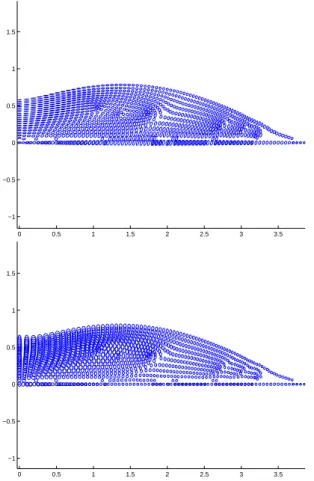
5 NUMERICAL RESULTS
The before presented model was applied to the sim-ulation of spinning a drop of CNT suspension, with initial Gaussian geometry. The model was composed of 977 nodes under axisymmetric assumptions for the flow (but not for the orientation field, assumed 3-d). The results on the orientation field for the carbon nan-otubes are shown in Fig. 4.
0 0.5 1 1.5 2 2.5 3 3.5 −1 −0.5 0 0.5 1 1.5 0 0.5 1 1.5 2 2.5 3 3.5 −1 −0.5 0 0.5 1 1.5
Figure 4: Orientation field for the CNT suspension at an intermediate step of the simulation (top: r− z orientation field.
Bottom: r− θ plane).
6 CONCLUSIONS
A model has been presented for the numerical simula-tion of spin coating of carbon nanotubes suspensions. The model is composed of a meshless (natural ele-ment) strategy for the flow that allows for a proper de-scription of the free-surface flow and a micro-macro description of the nanotube scale that allows for a suitable description of their orientation field. Other possibilities, such as the kinetic description derived from the Fokker-Planck equation or its equivalent sto-chastic (Itˆo) counterpart could also be applied in this same framework. They constitute our current effort of research.
REFERENCES
[1] I. Alfaro, J. Yvonnet, F. Chinesta, and E. Cueto. A study on the performance of Natural Neighbour-based Galerkin Methods. International Journal for Numerical Methods in
Engineering, 7(12):1436–1465, 2007.
[2] E. Cueto, M. Doblar´e, and L. Gracia. Imposing essen-tial boundary conditions in the Natural Element Method by means of density-scaled α-shapes. International Journal for
Numerical Methods in Engineering, 49-4:519–546, 2000.
[3] A. G. Emslie, F. T. Bonner, and L. G. Peck. Flow of a vis-cous liquid on a rotating shell. Journal of Applied Physics, 29(5):858–863, 1958.
[4] S. Iijima. Single-shell carbon nanotubes of 1-nm diameter.
Nature, 363:603–605, 1991.
[5] M. A. Martinez, E. Cueto, I. Alfaro, M. Doblare, and F. Chinesta. Updated Lagrangian free surface flow simu-lations with Natural Neighbour Galerkin methods.
Inter-national Journal for Numerical Methods in Engineering,
60(13):2105–2129, 2004.
[6] M. A. Mart´ınez, E. Cueto, M. Doblar´e, and F. Chinesta. Fixed mesh and meshfree techniques in the numerical sim-ulation of injection processes involving short fiber suspen-sions. Journal of Non-Newtonian Fluid Mechanics, 115:51– 78, 2003.
[7] R. Sibson. A Vector Identity for the Dirichlet Tesselation.
Mathematical Proceedings of the Cambridge Philosophical Society, 87:151–155, 1980.
[8] R. Sibson. A brief description of natural neighbour interpo-lation. In Interpreting Multivariate Data. V. Barnett
(Edi-tor), pages 21–36. John Wiley, 1981.
[9] N. Sukumar, B. Moran, and T. Belytschko. The Natural Ele-ment Method in Solid Mechanics. International Journal for