THÈSE PRÉSENTÉ À
L'UNIVERSITÉ DU QUÉBEC À CHICOUTIMI
COMME EXIGENCE PARTIELLE
DU DOCTORAT EN INGÉNIERIE
PAR
YU-MEIHAN
CORROSION DES COMPOSITES À MATRICE METALLIQUE DU
TYPE AI-B4C DANS LES SOLUTIONS AQUEUSES
A DISSERTATION PRESENTED TO
THE UNIVERSITY OF QUEBEC AT CHICOUTIMI
IN PARTIAL FULFILLMENT OF THE REQUIREMENTS FOR THE
DOCTOR OF PHILOSOPHY IN ENGINEERING
BY
YU-MEI HAN
CORROSION BEHAVIOR OF AI-B
4C METAL MATRIX
COMPOSITES IN AQUEOUS SOLUTIONS
Au cours des dernières années, les composites à matrice métallique (CMM) du type AI-B4C ont reçu une attention considérable en raison de leur légèreté, de leur conductivité thermique supérieure, de leur grande rigidité et de leur dureté. Grâce à la capacité particulière de l'isotope B10 à agir comme capteurs des neutrons, les composites AI-B4C ont
été utilisés par l'industrie nucléaire à titre de matériaux absorbeurs de neutrons pour la fabrication de la section interne de contenants de transport et de stockage des combustibles nucléaires périmés.
Bien que l'incorporation de particules céramiques dans la matrice d'aluminium permet d'améliorer les propriétés physiques et mécaniques de l'alliage de base, elle peut également modifier son comportement en corrosion. En outre, en tant que matériau absorbeur de neutrons utilisé dans les contenants de transport et de stockage pour les combustibles nucléaires usés, en particulier pour les applications de stockage humide, les composites A1-B4C sont continuellement en contact avec l'eau du bassin du réacteur (l'un
d'eux contenant de l'acide borique avec une concentration de B - 2500 ppm), un milieu généralement considéré comme étant légèrement corrosif. Ainsi, pour des raisons de sécurité évidentes, il devient très important de comprendre leur comportement en corrosion dans un milieu d'acide borique.
Cependant, à ce jour, force est de constater que très peu d'études ont été consacrées à la détermination de la tenue en corrosion des composites AI-B4C, et ce en particulier dans l'acide borique, contrairement au nombre considérable de travaux de recherche dédiés à la corrosion des composites Al-SiC et AI-AI2O3 dans divers environnements. Parmi la littérature traitant des phénomènes de corrosion, les solutions 3.5% NaCl et 0.5 M K2SO4 sont celles les plus couramment utilisées pour l'étude du comportement en corrosion des matériaux composites à matrice métallique. Par conséquent, la présente recherche a visé l'étude du comportement en corrosion des composites CMM du type AI-B4C dans trois solutions, soit H3BO3 contenant 2500 ppm B, 3.5% NaCl et 0.5 M K2SO4.
Parmi les solutions considérées, celle de NaCl a été identifiée comme étant celle induisant le plus de dommages au composite AI-B4C suivie, dans l'ordre, des solutions de K2SO4 et de H3BO3. Aucune corrosion appréciable n'a été observée dans les solutions d'acide borique et de K2SO4. Cependant, des piqûres apparentes ont été observées suite aux essais réalisés dans la solution de NaCl, et ce pour tous les matériaux étudiés. Pour l'alliage de base, le site préférentiel de piqûration était l'interface Al/Fe générée par la présence de particules intermétalliques. Pour le composite, l'interface AI/B4C était celle la plus favorable au développement de la corrosion localisée. Par ailleurs, il a été constaté que la
résistance à la corrosion des matériaux composites diminue lorsque la fraction volumique de B4C est augmentée.
Dans le but de contrer l'agressivité des phénomènes de corrosion observés pour le CMM dans la solution de NaCl, une partie des travaux réalisés s'est intéressée à l'inhibition de la corrosion du composite dans cet environnement. À cette fin, le benzotriazole (BTAH) a été utilisé comme inhibiteur de corrosion, et son effet a été systématiquement étudié en fonction de sa concentration, de la fraction volumique des particules de B4C et du temps d'inhibition, en utilisant la polarisation potentiodynamique, l'impédance électrochimique et la spectroscopie infrarouge de réflexion-absorption. Les résultats montrent que le BTAH est un inhibiteur efficace pour contrer la corrosion du composite AI-B4C dans une solution de 3,5 g/L NaCl, et son efficacité s'accroît lorsque sa concentration augmente. Pour une concentration de BTAH fixe et pour une même durée d'inhibition, l'augmentation de la fraction volumique de B4C dans le composite conduit à une plus grande efficacité d'inhibition du BTAH. L'efficacité du processus d'inhibition par le benzotriazole est également influencée par la durée d'immersion dans la solution: l'efficacité d'inhibition augmente durant les 18 premières heures d'immersion, alors qu'une prolongation de la durée d'immersion entraîne une diminution de l'efficacité du BTAH. Puisque le BTAH est un inhibiteur à caractère cathodique, il agit en s'adsorbant physiquement sur les particules de B4C à la surface du composite, lequel processus obéit à un isotherme d'adsorption de Freundlich.
Le mécanisme de corrosion dans la solution de K2SO4 a également été étudié en utilisant la spectroscopie d'impédance électrochimique et les méthodes de polarisation potentiodynamique. La microscopie optique, la microscopie électronique à balayage, ainsi que la profilométrie ont été utilisées pour étudier la morphologie de la surface des matériaux avant et après corrosion. De plus, la spectroscopie infrarouge de réflexion-absorption et la spectroscopie de photoélectrons X ont été utilisées pour identifier les produits de corrosion. Tel que révélé par les analyses de surface, l'espèce SO42" n'a pas
induit de piqûres à la surface du composite. Puisque les particules de B4C ont un caractère cathodique par rapport à la matrice périphérique d'aluminium, la corrosion galvanique entre les particules de B4C et la matrice Al a été considérée comme étant le principal mécanisme de corrosion. Les spectroscopies IRRAS et XPS ont montré que la bayerite (Al(0H)3) est le principal produit de corrosion généré durant une immersion prolongée dans la solution de K2SO4.
À titre de matériaux non structuraux utilisés pour la fabrication de contenants de transport et de stockage pour les combustibles nucléaires usés, les composites AA1IOO-B4C sont souvent assemblés à des matériaux structuraux tels que l'alliage d'aluminium AA6061 ou l'acier inoxydable 304 (SS304). Par conséquent, les composites AAHOO-B4C deviennent couplés galvaniquement aux alliages AA6061 ou SS304, ce qui peut avoir comme effet d'accélérer la corrosion du matériau le moins noble du couple. Pour cette
raison, les phénomènes de corrosion galvanique associés aux couples AA1100-B4C/AA6O6I et AA1100-B4C/SS304 dans les solutions 3.5% NaCl et H3BO3 contenant
2500 ppm de bore, ont été étudiés en utilisant un ampèremètre de résistance nulle (ZRA). Les effets dus à la dissimilarité des matériaux, à la solution d'immersion, et au rapport des aires des surfaces couplées galvaniquement ont été investigués. Dans la solution de NaCl, il a été déterminé que peu importe la nature du matériau structural couplé avec le CMM (SS304 ou AA6061), l'alliage de base (AA1100) ou les composites agissent toujours comme anode et les courants galvaniques mesurés sont directement proportionnels à la surface de la cathode. En revanche, dans la solution de H3BO3, les composites corrodent de façon préférentielle en présence de SS304, tandis que le AA6061 protège les composites de la dissolution. Bien que la corrosion galvanique soit contrôlée par la diffusion de l'oxygène à la cathode dans les solutions de NaCl et de H3BO3, son intensité est de loin inférieure dans la solution de H3BO3, en comparaison avec la solution de NaCl. Le contenu en B4C du composite joue également un rôle clé dans la corrosion galvanique, son influence étant modulée par la composition de la solution et les matériaux avec lesquels le composite est couplé.
Toutes les expériences ont été réalisées à température ambiante. Cependant, les composites AI-B4C sont immergés dans l'acide borique à une température élevée en situation réelle. Alors, l'auteur propose d'étudier le comportement à la corrosion des composites AI-B4C dans l'acide borique à une température élevée et d'enquêter sur la corrosion galvanique associés aux couples composites AI-B4C / SS304 et composites Al-B4C / AA6061 dans l'acide borique à une température élevée.
ABSTRACT
In recent years, AI-B4C metal matrix composites (MMCs) have received considerable attention due to their light weight, superior thermal conductivity, high stiffness and their hardness. Owing to the special capturing neutron ability of isotope B10,
AI-B4C MMCs have been increasingly used as excellent neutron absorber materials to fabricate the inside basket of transport and storage casks for spent nuclear fuels in the nuclear industry.
Although the incorporation of the ceramic particles into the Al matrix can enhance the physical and mechanical properties of the base material, it may also change its corrosion behavior. Besides, as neutron absorber material used in the spent fuels storage racks or transportation casks, especially in the wet storage application, AI-B4C MMCs are continuously in contact with the reactor pool water (i.e. one of them is the boric acid with B concentration of -2500 ppm), which is generally considered to be mildly corrosive. Thus, from the safety point of view, it is of paramount importance to understand their corrosion behavior in boric acid solution.
However, up to date, very limited studies have been devoted to the corrosion behavior of the AI-B4C MMCs, especially in boric acid, in contrast to considerable research in the corrosion behavior of Al-SiC and AI-AI2O3 composites in various environments. Among literature on corrosion, 3.5% NaCl and 0.5 M K2SO4 are the most commonly used solutions in studying the corrosion behavior of the composites. Therefore, the present research aimed at investigating the corrosion behavior of AI-B4C MMCs in three solutions, i.e. 2500 ppm boron-containing H3BO3 solution, 3.5% NaCl and 0.5 M K2SO4.
AI-B4C MMCs corroded most in the NaCl solution followed by K2SO4 and H3BO3
in order. No appreciable corrosion was observed in boric acid and sulfate solutions, while apparent pitting was observed in the NaCl solution for all materials studied. The preferential pitting sites were the Al/Fe intermetallics interfaces for the base alloy and the AI/B4C interfaces for the composites. Besides, it is observed that the corrosion resistance of the composites decreases with increase in B4C volume fraction.
The corrosion inhibition of AI-B4C MMCs in the NaCl solution was consequently investigated. Benzotriazole (BTAH) was tentatively used as a corrosion inhibitor for Al-B4C composites in the NaCl solution and its corrosion inhibition effect was systematically investigated as function of its concentration, volume fraction of B4C particles and inhibition time by using potentiodynamic polarization, electrochemical impedance and
inhibition efficiency increased when increasing the BTAH concentration. For the same BTAH concentration and immersion time, higher B4C volume fraction leads to higher corrosion inhibition efficiency. The inhibition efficiency of benzotriazole was also influenced by the inhibition time: The inhibition efficiency increases with the immersion time in the first 18 hours. However, prolonging the immersion time leads to a decrease in the inhibition efficiency. As BTAH was an inhibitor with a cathodic character, it inhibited corrosion by physically adsorbing on B4C particles at the composite surface, which obeyed the Freundlich adsorption isotherm.
The corrosion mechanism in K2SO4 solution was also studied by employing electrochemical impedance spectroscopy and potentiodynamic polarization methods. Optical and scanning electron microscopes as well as profilometry were employed to study the surface morphology of the material before and after corrosion. Moreover, infrared reflection-absorption spectroscopy (IRRAS) and x-ray photoelectron spectroscopy (XPS) were used to identify the corrosion products. SO42" species did not induce pitting of the
AAl 100-16 vol. % B4C. Since B4C particles showed a cathodic character with respect to the peripheral matrix, therefore, the galvanic corrosion between B4C particles and the Al matrix was considered to be the premier corrosion mechanism. IRRAS and XPS results showed that bayerite A1(OH)3 was the principal corrosion product.
As non-structural neutron absorber materials used to fabricate the inside basket of spent fuel storage racks or transportation casks, AAHOO-B4C MMCs are often assembled to structural materials AA6061 or SS304. Consequently, the AAHOO-B4C MMCs are galvanically coupled to AA6061 or SS304, which could potentially accelerate the corrosion of the less noble material. Therefore, the galvanic corrosion associated with AAl IOO-B4C MMCs/AA6061 and AAl IOO-B4C MMCs/SS304 couples in 3.5% NaCl and 2500 ppm boron-containing H3BO3 solutions was investigated by using a zero resistance ammeter (ZRA). The effects of dissimilar materials, immersion solution, and ratio of the coupled material areas are reported. In the NaCl solution, depending on the nature of the coupling agent (SS304 or AA6061), the composite or base alloy always acts as an anode and the measured galvanic currents are directly proportional to the cathode area. In contrast, in the H3BO3 solution, the composites preferentially dissolve in the presence of SS304, while AA6061 protects the metal matrix composites from dissolution. Although galvanic corrosion is controlled by oxygen diffusion at the cathode in both NaCl and H3BO3 solutions, its intensity is appreciably lower in the H3BO3 solution in comparison with the NaCl solution. The B4C content is also found to play a key role in galvanic corrosion; its influence is modulated by the solution composition and the materials to which the composite is galvanically coupled.
Above all experiments were carried out in room temperature. However, AI-B4C composites are immersed in boric acid at elevated temperature in the real situation. In the future work, the author suggests to studying the corrosion behavior of AI-B4C composites in boric acid at elevated temperature and investigating the galvanic corrosion associated with AI-B4C MMCs/SS304 and A1-B4C MMCs/AA6061 couples in boric acid at elevated
PUBLICATIONS
Journal articles and conference paper1. Y. Han, D. Gallant and X-G. Chen, "Investigation on Corrosion Behavior of the Al-B4C Metal Matrix Composite in a Mildly Oxidizing Aqueous Environment", Corrosion, 67(201 l),No.l 15005.
2. Y.-M. Han, D. Gallant and X-G. Chen, Corrosion Behaviour of Al-B4C Metal Matrix
Composites in H3BO3, K2SO4 and NaCl Solutions, Proceedings of the Light Metal , MetSoc, 2011, pp. 415-425.
3. Y.M. Han, D. Gallant and X-G. Chen, "Galvanic corrosion associated with Al-B4C
composites/6061 andAl-B4C composites/SS304 couples in NaCl andH3BO3 solutions", accepted by Electrochim. Acta. ,2012.
4. Y.-M. Han, D. Gallant and X-G. Chen, "Corrosion Inhibition ofAUB4C Metal Matrix
Composites in NaCl Solution by Benzotriazole (BTA)", accepted by Mater. Chem. Phys., 2012.
5. Y.-M. Han, D. Gallant and X-G. Chen, "Corrosion Characterization ofAl-B4C Metal
Matrix Composites in NaCl Solution", submitted to Electrochim. Acta., 2012, in revision.
6. Y.-M. Han, D. Gallant and X-G. Chen, Corrosion Characterization of Al-B4C Metal
Matrix Composites in H3BO3 Solutions, submitted to Corros. Sci., 2012, in revision.
Scientific posters
7. Y.M. Han, D. Gallant and X.-G. Chen, Galvanic corrosion associated with Al-B4C/AA6O6I and Al-B4C/SS304 couples in NaCl solution, the Encyclopedia of
Research on Aluminum in Quebec, Les Presses de 1'aluminum (PRAL), Trois-Riviere, 2012.
8. Y.M. Han, D. Gallant and X.-G. Chen, Inhibition by Benzotriazole of Al-B4C Metal
Matrix Composites Corrosion in NaCl Solution, the Encyclopedia of Research on Aluminum in Quebec, Les Presses de Paluminum (PRAL), Montreal, 2011.
9. Y.M. Han, D. Gallant, B. Arsenault and X.-G. Chen, Investigation on Corrosion Behavior of AI-B4C Metal Matrix Composite in a Mildly Oxidizing Aqueous Environment, the Encyclopedia of Research on Aluminium in Quebec, Les Presses de l'aluminium (PRAL), Quebec, 2010.
10. Y.M. Han, D. Gallant, B. Arsenault and X.-G. Chen, Corrosion Mechanisms ofAl-B4C
Metal Matrix Composites in Sulfate Solution, the Encyclopedia of Research on Aluminum in Quebec, Les Presses de l'aluminium (PRAL), Montreal, 2009.
ACKNOWLEDGEMENTS
It is a great pleasure to have the chance to convey my thanks to all those who were
involved, directly or indirectly, in making this project a success. First and foremost, I
would like to express my special thanks to my director, Professor X.-Grant Chen and
co-director, Dr. Danick Gallant, for giving me the opportunity to undertake this research, for
their expertise guidance, continuous encouragement, and patience during my Ph. D study.
Without them, I wouldn't have come so far.
I would like to express my appreciation to all members of Natural Research
Council Canada (NRC)-Saguenay site for creating such a comfortable studying and
experimental environment during my five years of research. Particularly, I would like to
express my profound gratitude to Ms. Amélie Ruest, Ms. Sandy Laplante, Ms. Geneviève
Simard and Ms. Hélène Grégoire, not only for their professional technical assistance
during experiments, but also for the happy time that they shared with me. I would also like
to thank Mr. Bernard Arsenault, the director of NRC-Saguenay site, who introduced me to
NRC-Saguenay site and gave generous encouragement in my research work. Many thanks
also go to Mr. Stephan Simard, Mr. Mojtaba Eskandarian and Ms. Saleema
Noormohammed.
I am grateful for all members of NESERC Industry Chair in Metallurgy of
stimulating discussions at the half-month meetings and all the fun that we have had during
the last five year.
I wish to express my grateful acknowledgement to the financial support from the
Natural Sciences and Engineering Research Council of Canada (NSERC), from Rio Tinto
Alcan and from the Natural Research Council Canada (Saguenay site) through the NSERC
Industrial Research Chair in Metallurgy of Innovative Aluminium Transformation at the
University of Quebec in Chicoutimi.
Finally, my endless thanks go to my beloved parents, grandparents, brother and
husband for their love and immense support-both spiritually and practically. I also would
RESUME i ABSTRACT iv PUBLICATIONS. vii ACKNOWLEDGEMENTS viii TABLE OF CONTENTS x LIST OF TABLES xv
LIST OF FIGURES xvii
CHAPTER 1
INTRODUCTION 1
1.1 Definition of the Problem .2 1.2 Objectives 5 References 6
CHAPTER 2
LITERATURE REVIEW 8
2.1 A1-B4C Composites 9
2.1.1 Fabrication Process of Al-B4CMMCs 11
2.1.3 Applications of AI-B4C MMCs in the Nuclear Industry 15 2.2 Forms of Corrosion 19 2.3 Corrosion of Aluminum Metal Matrix Composites 23 2.4 Galvanic Corrosion of Metal Matrix Composites Associated With Dissimilar
Materials 27 2.5 Corrosion Prevention 28 2.6 Basic Aspects of Electrochemical Processes 32 2.6.1 Electrical Double Layer 32 2.6.2 Three-Electrode Cell 34 2.7 Corrosion testing and evaluation techniques 35 2.7.1 Potentiodynamic Polarization 37 2.7.2 Electrochemical Impedance Spectroscopy (EIS) 40 2.7.3 Zero Resistance Ammetry 48 References 49
CHAPTER 3
EXPERIMENTAL PROCEDURES 55
3.1 Sample Preparation and Solutions 56 3.2 Electrochemical Experiments 59 3.3 Microstructural Analysis 60 3.4 Infrared Reflection-Absorption Spectroscopy 61 3.5 X-Ray Photoelectron Spectroscopy 61 References... 61
CHAPTER 4
CORROSION BEHAVIOUR OF A1-B4C METAL MATRIX COMPOSITES IN H3BO3, K2SO4 AND NaCl SOLUTIONS 62
Abstract 63 4.1 Introduction 64 4.2 Materials and Methods 65 4.3 Results and Discussion ..67 4.3.1 Potentiodynamic Polarization 67 4.3.2 Electrochemical Impedance Spectroscopy 72 4.4 Conclusions 77 References 78
CHAPTER 5
INVESTIGATION ON CORROSION BEHAVIOR OF THE A1-B4C METAL MATRIX COMPOSITES IN A MILDLY OXIDIZING AQUEOUS ENVIRONMENT 81 Abstract 82 5.1 Introduction 83 5.2 Experimental Procedure 85 5.2.1 Material Preparation 85 5.2.2 Electrochemical Experiments 86 5.2.3 Microstructural Analysis 88 5.2.4 Infrared Reflection-Absorption Spectroscopy 88 5.2.5 X-Ray Photoelectron Spectroscopy 89 5.3 Results and Discussion 89
5.3.1 Potentiodynamic Polarization of A1-B4C MMC in K2SO4 and NaCl
Solutions ...' 89 5.3.2 Electrochemical Impedance Spectroscopy Investigation of AI-B4C
MMC in 0.5 M K2SO4 93
5.4 Conclusions 110 References I l l
CHAPTER 6
CORROSION INHIBITION OF A1-B4C METAL MATRIX COMPOSITES IN A NaCI SOLUTION BY BENZOTRIAZOLE 114
Abstract 115 6.1 Introduction 116 6.2 Experimental Procedures 118 6.2.1 Preparation of Samples and Electrolytes 118 6.2.2 Electrochemical Measurements 119 6.2.3 Infrared Reflection-Absorption Spectroscopy 120 6.3 Results and Discussion 120 6.3.1 Effect of BTAH on the Inhibition Efficiency 120 6.3.2 Effect of B4C Particle Volume Fraction on The inhibition Efficiency 124 6.3.3 Effect of Immersion Time 128 6.3.4 Electrochemical Impedance Spectroscopy (EIS) Measurements 131 6.3.5 Infrared Reflection Absorption Spectroscopy (IRRAS) 135 6.3.6 Adsorption Isotherm 137 6.4 Conclusions 139 References 140
CHAPTER?
GALVANIC CORROSION ASSOCIATED WITH A1-B4C COMPOSITES/SS304 AND A1-B4C COMPOSITES/AA6061 COUPLES IN NaCI AND H3BO3 SOLUTIONS 144
Abstract 145 7.1 Introduction . 146 7.2 Experimental Procedure 147 7.2.1 Sample Preparation 147 7.2.2 Galvanic Coupling Measurement 148 7.3 Results and Discussion 149 7.3.1 Open Circuit Potentials of Uncoupled Materials 149 7.3.2 Effect of Dissimilar Materials 151 7.3.3 Effect of Solution 155 7.3.4 Effect of Area Ratio 160 7.4 Conclusions 170 References 171
CHAPTER 8
CONCLUSIONS & RECOMMENDATIONS FOR FUTURE WORK 173
8.1 Conclusions 174 8.2 Recommendations for Future Works 177
Table Table Table Table Table Table Table 2.1 3.1 4.1 4.2 5.1 5.2 5.3 Table 5.4 Table 6.1 Table 6.2 Table 6.3 Table 6.4 Table 6.5 Table 6.6 Table 7.1 Table 7.2
LIST OF TABLES
Typical composition of AAHOO-B4C composites 11 Designate chemical composition of the base alloy AA1100 57 Chemical composition ofthe base alloy AA1100 66 Electrochemical parameters derived from polarization curves 70 Typical chemical composition of AA 1100 - 15 wt. % B4C
composite 86 Corrosion parameters calculated from polarization curves 91 Electrochemical parameters calculated from the equivalent circuit in
Figure 5.7 97 Electrochemical parameters calculated from the equivalent circuit in. Figure 5.9 99 Designated chemical composition ofthe base AA1100 alloy 118 Electrochemical parameters obtained from PDP measurements of
AA1100-16 vol.% B4C in 3.5 g/L NaCl with different
concentrations of BTAH 123 Electrochemical parameters obtained from PDP measurements of
AA1100, AA1100-16 vol.% B4C, and AA1100-30 vol.% B4C in a
3.5 g/L NaCl solution in the presence and absence of 0.05M of
BTAH 127 Electrochemical parameters obtained from PDP measurement of
AA1100-16 vol.% B4C in a 3.5 g/L NaCl solution with different
immersion times 130 Electrochemical parameters obtained from PDP measurement of
AA1100-16 vol.% B4C in a 3.5 g/L NaCl + 0.05M of BTAH
solution with different immersion times 130 Electrochemical parameters obtained from EIS measurements of Al
composites in a 0.35 % NaCl solution with different BTAH
concentrations 134 Chemical composition of the base alloy AA1100 148 Open circuit potential ( ^ ) of materials investigated in 3.5% NaCl
and 2500 ppm B-containing H3BO3 solutions 150 Table 7.3 Average galvanic current J~ °f different couples and potential
difference ^ of uncoupled dissimilar material in 3.5% NaCl
solution 154 Table 7.4 Average galvanic current J~ °f different couples and potential
difference Acps of uncoupled dissimilar materials in 2500 ppm
LIST OF FIGURES
Figure 2.1 Classification of composite materials with metal matrixes 9 Figure 2.2 Schematic diagram showing three types of metal matrix component
materials 10 Figure 2.3 General steps in the powder metallurgy process.[8] 12
Figure 2.4 General steps in liquid mixing process 13 Figure 2.5 (a) Microstructure of AA1100-15 vol.% B4C and (b) Ti Mapping
showing the Ti barrier layer at B4C and matrix interfaces 15 Figure 2.6 Optical micrographs showing (a) large clusters of secondary phases
and (b) the uniform distribution of boron carbide in the matrix with the addition of Ti in AA6351-15 vol. % B4C composite obtained
after 30 min processing time 15 Figure 2.7 Spent nuclear fuel wet storage pool 16 Figure 2.8 Cross section of a typical PWR storage cell 17 Figure 2.9 Multiple purpose canister of dry storage 18 Figure 2.10 Schematic diagram showing the uniform corrosion 19 Figure 2.11 Schematic diagram showing the galvanic corrosion 20 Figure 2.12 Schematic diagram showing the pitting corrosion 20 Figure 2.13 Schematic diagram showing the crevice corrosion 21 Figure 2.14 Schematic diagram showing stress corrosion cracking 21 Figure 2.15 Schematic diagram showing intergranular corrosion .22 Figure 2.16 Schematic diagram showing selective corrosion 22 Figure 2.17 Schematic diagram showing erosion corrosion ..23 Figure 2.18 Scanning electron micrographs of samples corroded in sea water at
300 K (a) base alloy (6061 Al) and (b) as-cast composite 24 Figure 2.19 Schematic diagram showing the microstructure (a) 7075-SiCp
MMC and (b) 7075 alloy.1 26
Figure 2.20 Chemical structure of BTAH 32 Figure 2.21 Proposed model of the double-layer region under conditions where
anions specially adsorbed 33 Figure 2.22 Three-electrode cell and notation for the difference electrodes 34
Figure 2.23 Theoretical anodic polarization scan 38 Figure 2.24 Potentiodynamic polarisation diagrams for C/AS41 and
C/AS41(0.5% Ca) Mg MMCs in 100 ppm NaCl solution, pH 12.[26] 39
Figure 2.25 Tafel slope calculation 40 Figure 2.26 Sinusoidal current response in a linear system 42 Figure 2.27 (a) Nyquist and (b) Bode plot for the Randle cell 43 Figure 2.28 Simple equivalent circuit with one time constant 44 Figure 2.29 Nyquist plot showing the ideal semicircle (curve 1, ^=1.0) and
depressed semicircle (curve 2, ^=0.8) 45 Figure 2.30 Nyquist plot of A1/0.16M NHLf tartrate at (a) PH = 6 and T = 298K
with electrode potentials: - 670 mV (•); - 470 mV (A); - 270 mV (0); - 70 mV (•); + 330 mV (o); (b) T = 298K, E = 330 mV, PH =5 (o);
6(A);7(n) 46 Figure 2.31 Equivalent circuit used to interpret the Nyquist plot in Figure 2.30 46 Figure 2.32 (a) Equivalent circuit for the total electrode impedance; (b) Nyquist
plot for the circuit in (a) when 1/CR3<R2/L 47
Figure 3.1 EG&G PAR flat cell used in the present study and the
three-electrode system 60 Figure 3.2 Image of scanning electron microscope used in the present study 60 Figure 4.1 Potentiodynamic polarization curves recorded on AA1100-16 vol.
% B4C in 2500 ppm boron-containing H3BO3, 0.5 M K2SO4 and
3.5% NaCl 68 Figure 4.2 Potentiodynamic polarization curves recorded on AA1100-30 vol.
% B4C in 2500 ppm boron-containing H3BO35 0.5 M K2SO4 and
3.5% NaCl 69 Figure 4.3 Potentiodynamic polarization curves recorded on base alloy
AA1100 in 2500 ppm boron-containing H3BO3, 0.5 M K2SO4 and
3.5% NaCl 70 Figure 4.4 Tafel plot of AA1100-16 vol. % B4C in 0.5 M K2SO4 showing that
jcorr value is obtained by the intersection of the extrapolated cathodic
branch at the corrosion potential 71 Figure 4.5 SEM image presenting the surface morphology of AA1100-16 vol.
% B4C (a) before and (b) after polarization in 3.5% NaCl. Initiation
of pitting (marked as black arrows) is observed at the A1/B4C
Figure 4.6 SEM image presenting the surface morphology of AA1100 alloy (a) before and (b) after polarization in 3.5% NaCl. Initiation of pitting (marked as black arrows) at Al/intermetallic phase is observed after polarization. EDS result shows that the intermetallic is
Fe-containing phases 72 Figure 4.7 Typical Bode plots of AA1100? -16 vol. % B4C and -30 vol. % B4C
composites obtained after a 3-hour immersion in 2500 ppm
B-containing H3BO3 solution 74 Figure 4.8 Typical Bode plots of AA1100, -16 vol. % B4C and -30 vol. % B4C
composites obtained after a 1-hour immersion in 0.5 M K2SO4
solution 74 Figure 4.9 Typical Bode plots of AA1100, AA1100-16 vol. % B4C and
AA1100-30 vol. % B4C obtained after a 1-hour immersion in 3.5%
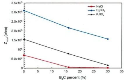
NaCl solution 75 Figure 4.10 Average impedances measured in three solutions in the frequency
range 0.01 ~ 0.04 Hz as a function of B4C percent in the MMCs 75
Figure 4.11 Damage function as function of B4C percent for materials
investigated in 2500 ppm B-containing H3BO3, 0.5 M K2SO4 and
3.5% NaCl solutions 77 Figure 5.1 Typical potentiodynamic polarization curve of AA1100-16 vol. %
B4C composite in a 0.5 M K2SO4 solution after a 3-hour immersion
period. (Inset: Tafel plot showing the corrosion current j was obtained at the intercept of the extrapolation of cathodic branch,
jcorr = 74 nA.cm"2, Ecorr = -400.7 mV) 90
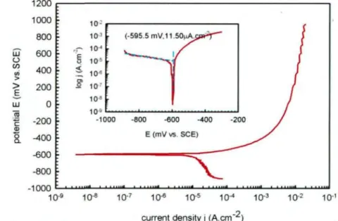
Figure 5.2 Typical potentiodynamic polarization curve of AA1100-16 vol. % B4C composite in a 3.5% NaCl solution after a 3-hour immersion
period. (Inset: Tafel plot showing the corrosion current jcorr was
obtained at the intercept of the extrapolation of cathodic branch. jcorr
= 11.50 ^lA.cin2, ECorr = -595.5 mV) 90
Figure 5.3 SEM image comparing the surface morphology of the composite (a)
before and (b) after polarization in a 0.5 M K2SCU solution 92 Figure 5.4 SEM image presenting the occurrence of pitting at the interface of
A1/B4C particles on an AA1100-16 vol. % B4C MMC surface
during polarization in a 3.5% NaCl solution 93 Figure 5.5 Optical micrographs showing (a) uniform B4C particle distribution
and (b) defects on an AA1100-16 vol. % B4C MMC surface;
topographic profile of (c) uniform surface and (d) defective surface 94 Figure 5.6 Typical (a) Nyquist and (b) Bode plots of AA1100-16 vol. % B4C
MMC samples with uniform surfaces obtained after a 3-hour immersion period in a 0.5 M K2SO4 solution (experimental data and
fitted curves are respectively presented by points and lines) 96 Figure 5.7 Equivalent circuit to interpret EIS spectra obtained from samples
with uniform surface 96 Figure 5.8 Typical (a) Nyquist and (b) Bode plots of AA1100-16 vol. % B4C
MMC samples with defective surfaces obtained after a 3-hour immersion period in a 0.5 M K2SO4 solution (experimental data and
fitted curves are respectively presented by points and lines) 98 Figure 5.9 Equivalent circuit to interpret EIS spectra obtained from samples
with defective surfaces (the pore section was taken from Figure 5.5;
RE: reference electrode; WE: working electrode). 99 Figure 5.10 (a) Nyquist plots of the composite with uniform surface obtained
after 3, 24, 48, 96 and 120 hours' immersion times in a 0.5 M K2SO4 solution; (b) plot showing polarization resistance varying
with time 100 Figure 5.11 Optical and SEM micrographs showing the surface morphology of
AA1100 - 16 vol. % B4C MMC (a) before corrosion and after a
120-hour immersion in a 0.5 M K2SO4 solution (b) with agitation
and (c) without agitation 102 Figure 5.12 Corresponding EDS results of Figure 5.11: "Spectrum 1" points the
B4C particle; "Spectrum 2" reveals that the B4C boundaries are rich
in Ti, Al, O and trace elements; "Spectrum 3" exhibits the Al matrix under the cracked layer, "Spectrum 4" and "Spectrum 5" indicate
the cracked and uncracked layer as Al oxide 103 Figure 5.13 IRRAS spectra of AA1100-16 vol. % B4C MMCs obtained from
different conditions: (a) before and after 120-hour corrosion, (b) the
difference of the two spectra seen in (a) with a corrected baseline 105 Figure 5.14 X-ray photoelectron A12p spectra of AA1100 -16 vol. % B4C
samples (a) before corrosion and (b) after 120 hours corrosion in a
0.5 M K2SO4 solution 106
Figure 5.15 (a) SEM image showing the preferential deposition of small nodules over B4C particles; (b) and (c) EDS elemental mappings showing
that the small nodules contained within the circle in (a) are
essentially composed of Cu and 0 108 Figure 5.16 The schematic diagram showing the preferential deposition
mechanism of copper oxide over B4C particles 110
Figure 6.1 Chemical structure of BTAH 117 Figure 6.2 Potentiodynamic polarization curves of AA1100-16 vol.% B4C in a
3.5 g/L NaCl solution containing different BTAH concentrations 121 Figure 6.3 Variation of inhibition efficiency IE (%) as a function of BTAH
concentration in a 3.5 g/L NaCl solution 124 Figure 6.4 Potentiodynamic polarization curves of AA1100, AA1100-16 vol.%
B4C and AA1100-30 vol.% B4C immersed in (a) 3.5 g/L NaCl and
(b) 3.5 g/L NaCl +0.05M of BTAH solution for one hour 126 Figure 6.5 Plot showing the inhibition efficiency of 0.05 M of BTAH in a
3.5g/L NaCl solution as a function of the B4C particles volume
fraction 127 Figure 6.6 Potentiodynamic polarization curves of AA1100-16 vol.% B4C in (a)
3.5 g/L NaCl and (b) 3.5 g/L NaCl +0.05M of BTAH with different
immersion times 129 Figure 6.7 Plot showing that the Eb-Ecorr obtained in the solution with BTAH
has a linear relationship with the immersion times 131 Figure 6.8 Nyquist plots of AA1100-16 vol.% B4C in 3.5 g/L NaCl with
different concentrations of BTAH (experimental data and fitted
curves are respectively presented by points and lines) 132 Figure 6.9 The equivalent circuit used to interpret the experimental data
obtained in a 3.5 g/L solution in the presence of BTAH at different
concentrations 133 Figure 6.10 IRRAS spectra of AA1100-16 vol.% B4C MMCs obtained after
immersion in a 3.5 g/L NaCl with different BTAH concentrations 136 Figure 6.11 Band area of A1(OH)3 centered at 3500 cm"1 as a function of
inhibition efficiency 136 Figure 6.12 Plot of log 0 vs log CBTAH (Freundlich adsorption isotherm)
obtained from the BTAH surface coverage values presented in
Table 6.2 138 Figure 7.1 Time behavior of galvanic current / for AA1100 coupled to
SS304andAA6061in3.5%NaCl 152 Figure 7.2 Time behavior of galvanic current / for AA1100-16 vol.% B4C
coupled to SS304 and AA6061 in 3.5% NaCl 153 Figure 7.3 Time behavior of galvanic current / for AA1100-30 vol. % B4C
coupled to SS304 and AA6061 in 3.5% NaCl. 153 Figure 7.4 Time behavior of galvanic current / for AA1100 coupled to
SS304 and AA6061 in 2500 ppm B-containing H3BO3 156 Figure 7.5 Time behavior of galvanic current / for AA1100-16 vol. % B4C
Figure 7.6 Time behavior of galvanic current / for AA1100-30 vol.% B4C
coupled to SS304 and AA6061 in 2500 ppm B-containing H3BO3 157 Figure 7.7 Time behavior of galvanic potential for AA1100, AA1100-16 vol.%
B4C and AA1100-30 vol.% B4C composites coupled to SS304 in
2500 ppm B-containing H3BO3 solution 157 Figure 7.8 Surface morphology of the AA1100-16 vol.% B4C composite
coupled to SS304 after 24 h immersion in (a) 3.5% NaCl and (b)
2500 ppm B-containing H3BO3 solution (100x) 158 Figure 7.9 Average galvanic current density / " as function of ^s of
uncoupled dissimilar materials in 2500 ppm B-containing H3BO3
solution 160 Figure 7.10 Galvanic current / as function of time and area ratio Ac IAA for
AA1100-16 vol. % B4C coupled to SS304 in 3.5% NaCl solution 162
Figure 7.11 Galvanic potential ç as function of time for AA1100-16 vol. %
B4C/SS304 couple with different area ratios in 3.5% NaCl solution 162
Figure 7.12 Galvanic current / as function of time with oxygen purging during the test for AA1100-16 vol. % B4C/SS304 couple in 3.5% NaCl
solution (Ac IAA =1:1) 164
Figure 7.13 Galvanic current density \A with respect to anode (AA1100-16 vol.
% B4C) as function of time and area ratio for AA1100-16 vol. %
B4C/SS304 couple in 3.5% NaCl solution .166
Figure 7.14 Galvanic current density f with respect to cathode (SS304) as function of time and area ratio for AA1100-16 vol. % B4C/ SS304
couple in 3.5% NaCl solution ..166 Figure 7.15 Dependence of \A on area ratio AC/AA in 3.5% NaCl solution 167
Figure 7.16 Dependence of corrosion rate r of AA1100-16 vol. % B4C on area
ratio AC/AA in 3.5% NaCl solution 168
Figure 7.17 Galvanic current *as function of time and area ratio ACIAA for
Al-16 vol. % B4C coupled to SS304 in 2500 ppm B-containing
H3BO3 solution 169 Figure 7.18 Galvanic potential as function of time for Al-16 vol. % B4C/SS304
couple with different area ratios in 2500 ppm B-containing H3BO3
INTRODUCTION
1.1 Definition of the Problem
AI-B4C metal matrix composites (MMCs) have received considerable attention due
to their light weight, superior thermal conductivity, high stiffness and their hardness.[1]
Owing to the special capturing neutron ability of isotope B10, AI-B4C MMCs have been
increasingly used as excellent neutron absorber materials to fabricate the inside basket of
transport and storage casks for spent nuclear fuels in the nuclear industry. ^2'5\
However, although the incorporation of the particles into the Al matrix can enhance
the physical and mechanical properties of the base material, it may also change its
corrosion behavior.^ Bhat et alP^ investigated the corrosion behavior of the 6061 Al-SiCp
composite and its base alloy in seawater using the potentiodynamic polarization technique.
It was found that the composite corroded faster than its base alloy and that composite
corrosion was mainly confined to the interface as opposed to the uniform corrosion
observed for the base alloy. Sun et al. [8] also studied the corrosion behavior of 6061
Al-SiCp MMCs in a NaCl solution. With the observation that the pitting degree rose with an
increase of SiC content, it is presumed that the occurrence of pitting corrosion depends on
and consequently more pit initiation sites. Singh et al}9] similarly studied the influence of
SiC additions on the corrosion behavior of 2014 alloy in a 3.5% NaCl solution at 30 °C. It
was revealed that the addition of 10 wt. % SiC into the base alloy considerably increases its
corrosion resistance, while the addition of 25 wt. % SiC into the base alloy decreases the
overall corrosion resistance of the material. From a more general perspective, Roepstorff et
al. ^10] reported that the corrosion resistance of metal matrix composites can essentially be
affected by three processes: (1) galvanic coupling of the metal and reinforcement, (2)
crevice attack at the metal/reinforcement interface, and (3) preferential localized attack on
possible reaction products between metal and ceramic. According to Hihara et al.[n\
among these corrosion mechanisms, the galvanic corrosion between aluminum and
reinforcement particles is of primary concern when studying MMC corrosion behavior.
As neutron absorber material used in the spent fuel storage racks or transportation
casks, AI-B4C MMCs are placed between spent nuclear fuel assemblies. In the wet storage
application, AI-B4C MMCs are continuously in contact with the reactor pool water (i.e. one
of them is the boric acid with B concentration of -2500 ppm), which is generally
considered to be mildly corrosive J12^ Thus, from the safety point of view, it is of paramount
importance to understand their corrosion behavior in boric acid solution. However, up to
date, very limited studies have been devoted to the corrosion behavior of the A1-B4C
MMCs, especially in boric acid, in contrast to considerable research in the corrosion
behavior of Al-SiC and AI-AI2O3 composites in various environments. Among literature on
the corrosion behavior of the composites. Therefore, the present research aimed at
investigating the corrosion behavior of AI-B4C MMCs in three solutions, i.e. 2500 ppm
Boron-containing H3BO3 solution, 3.5% NaCl and 0.5 M K2SO4.
A variety of methods such as anodizing and rare earth chloride inhibition have been
suggested for the protection of aluminum metal matrix composites from corrosion. The
organic compounds containing heteroatoms N, O, and S in the molecules were reported to
be effective inhibitors for Al alloys in an environment containing aggressive ions [13"15]. It is
believed that organic compounds inhibit the corrosion of Al alloys in some aggressive
media by adsorbing on the material surface and forming a physical barrier between the
material surface and the aggressive media. Benzotriazole, conveniently abbreviated as
BTAH, has been known to be an effective inhibitor for copper and its alloys for more than
sixty years.[16"18] It has been recently reported to be an effective corrosion inhibitor for iron
and aluminum alloys. In the present research, benzotriazole was tentatively used as a
corrosion inhibitor for AI-B4C composites in a NaCl solution.
As non-structural neutron absorber materials used to fabricate the inside basket of
spent fuel storage racks or transportation casks, AAHOO-B4C MMCs are often assembled
to structural materials AA6061 aluminum alloy or 304 stainless steel (SS304).
Consequently, the AAHOO-B4C MMCs are galvanically coupled to AA6061 or SS304,
which could potentially accelerate the corrosion of the less noble material. Such galvanic
corrosion phenomenon is especially at risk when assemblies are used in the wet storage
application of spent nuclear fuels that implies immersion in a mildly corrosive reactor pool
AAHOO-B4C MMCs/AA6061 couples. Accordingly, we have also investigated the
galvanic corrosion of AAHOO-B4C MMCs with different B4C levels (16 and 30 vol.%)
coupled to AA6061 or SS304 in 3.5% NaCl and 2500 ppm boron-containing H3BO3
solutions considering the effect of dissimilar materials, solution and area ratios of coupled
materials.
1.2 Objectives
The present research aims to study the corrosion behavior of AI-B4C MMCs in a
lab-scale condition that simulates the environment to which neutron absorber materials are
exposed. This general objective could be achieved by four sub-objectives:
(1) Investigating the corrosion susceptibility of AI-B4C MMCs in 2500 ppm
boron-containing H3BO3 in comparison with those in 0.5 M K2SO4 and 3.5% NaCl
solutions and finding out the influence of B4C particle levels on the corrosion resistance of
the composites;
(2) Studying the corrosion mechanism of AI-B4C MMCs in a 0.5 M K2SO4
solution, 2500 ppm boron-containing H3BO3 and 3.5% NaCl solutions;
(3) Systematically investigating the inhibitive effect of BTAH on the corrosion
of AI-B4C composites in a 3.5 g/L NaCl solution as a function of BTAH concentrations,
AA6061 or SS304 in 3.5% NaCl and 2500 ppm boron-containing H3BO3 solutions
considering the effect of dissimilar materials, solution and area ratios of coupled materials.
References
[1] X.-G. Chen, "Application of AI-B4C Metal Matrix Composites in the Nuclear Industry for Neutron Absorber Materials", in: Proceedings of the Symposium on Solidification Processing of Metal Matrix Composites, W.H. Hunt and N. Grupta (Eds.), TMS, 2006, pp. 343-350.
[2] X.-G. Chen, R. Hark, "Development of Al-30%B4C Metal Matrix Composites for
Neutron Absorber Material", in: Proceedings of Aluminium Alloys: Fabrication, Characerization and Applications W. Yin and S.K. Das (Eds.), TMS, 2008, pp. 3-9. [3] G. Bonnet, V. Rohr, X.-G. Chen , J.L. Bernier, R. Chiocca, H. Issard, "Use of
Alcan's A1-B4C Metal Matrix Composites as Neutron Absorber Material in TN International's Transportation and Storage Casks", Packaging, Transport Storage and Security of Radioactive Material 20 (2009) 98-102.
[4] A.R. Kennedy, "The Microstructure and Mechanical Properties of Al-Si-B4C Metal Matrix Composites", Journal of Materials Science. 37 (2002) 317-323.
[5] C. Brown, C.G. Interrante, L.R. Abramson, "Neutron Absorbers: Qualification and Acceptance Tests", in: Proceeding of the 13th International Symposium on
Packaging and Transportation of Radioactive Materials (PATRAM), (Eds.), 2001, pp. 201-205.
[6] L.H. Hihara, R.M. Latanision, "Corrosion of Metal Matrix Composites", International Materials Review. 39 (1994) 245-263.
[7] M.S.N. Bhat, M.K. Surappa, H.V.S. Nayak, "Corrosion Behaviour of Silicon Carbide Particle Reinforced 6061/A1 Alloy Composites", Journal of Materials Science, 26 (1991) 4991-4996.
[8] H. Sun, E.Y. Koo, H.G. Wheat, "Corrosion Behavior of SiCp/6061 Al Metal Matrix Composites", Corrosion, 47 (1991) 741-753.
[9] I.B. Singh, D.P. Mandai, M. Singh, S. Das, "Influence of SiC Particles Addition on the Corrosion Behavior of 2014 Al-Cu Alloy in 3.5% NaCl Solution", Corrosion Science, 51 (2009) 234-241.
[10] S. Roepstorff, E. Maahn, "Corrosion Resistance of Aluminum-Silicon Carbide Composite Materials", in: Proceeding of 12th Scandinavian Corrosion Congress and Eurocorrf92, P.J. Tunturi (Eds.), Corrosion Society of Finland, 1992, pp.
[12] H. Ding, L. Hihara, "Localized Corrosion Currents and pH Profile Over B4C, SiC,
and AI2O3 Reinforced 6092 Aluminum Composites: I. In 0.5 M Na2SÛ4 Solution", Journal of the Electrochemical Society, 152 (2005) B161-B167.
[13] G. Bereket, A. Pinarbaçi, "Electrochemical Thermodynamic and Kinetic Studies of the Behaviour of Aluminium in Hydrochloric Acid Containing Various Benzotriazole Derivatives", Corrosion Engineering Science and Technology, 39 (2004)308-312.
[14] V. Branzoi, F. Golgovici, F. Branzoi, "Aluminium Corrosion in Hydrochloric Acid Solutions and the Effect of Some Organic Inhibitors", Materials Chemistry and Physics, 78 (2003) 122-131.
[15] .Z. Grubac, R. Babic, M. Metikos-Hukovic, "Application of Substituted N-arylpyrroles in the Corrosion Protection of Aluminium in Hydrochloric Acid", Journal of Applied Electrochemistry, 32 (2002) 431-438.
[16] K.F. Khaled, M.M. Al-Qahtani, "The Inhibitive Effect of Some Tetrazole Derivatives Towards Al Corrosion in Acid Solution: Chemical, Electrochemical and Theoretical Studies", Materials Chemistry and Physics, 113 (2009) 150-158.
[17] T. Kosec, I. Milosev, B. Pihlar, "Benzotriazole As An Inhibitor of Brass Corrosion in Chloride Solution", Applied Surface Science, 253 (2007) 8863-8873.
[18] F.M. Bayoumi, A.M. Abdullah, B. Attia, "Kinetics of Corrosion Inhibition of Benzotriazole to Copper in 3.5% NaCl", Materials and Corrosion, 59 (2008) 691-696.
LITERATURE REVIEW
2.1 AI-B4C Composites
Metal matrix composites (MMCs) are metals reinforced with either particles or fibers
and are particularly suited for applications that require strength and stiffness. They are
being considered as good candidates for replacing conventional alloys in many industries
such as aerospace, automotive, and sport due to their specific strength and stiffness
compared to their matrix alloys.[1]
Metal matrix composites could be classified in consideration of type and contribution
of reinforcement components in particle-, layer-, fiber-, and penetration composite
materials (see Figure 2.1). Fiber composite materials could further be classified into
continuous fiber composite materials (multi- and monofilament) and short fibers or, rather,
whisker component materials, as seen in Figure 2.2.[2]
Classification of the composite materials with metal matrix Composites with metal phase
1
dispersion hardened and particle composites1 1
Layer composites (Laminates) Fiber composites infiltration compositesMono filaments Whiskers/ Particle
Short fibers
Figure 2.2 Schematic diagram showing three types of metal matrix component materials. '21
Of all metal matrix composites, aluminum matrix composites have been the most
popular due to their low cost over most other MMCs. In addition, they offer high
strength-to-density ratios, excellent thermal conductivity, high shear strength, excellent abrasion
resistance, high-temperature operation, non-flammability, minimal attack by fuels and
solvents, and the ability to be formed and treated on conventional equipment.[1]
Boron carbide (B4C) appears to be an interesting strengthening agent for aluminum
based composites with a low density (2.51 g/cm3), a hardness just below that of diamond,
excellent thermal stability and remarkable chemical inertness.'31 Owing to the specific
ability of the 10B isotope to capture neutrons, A1-B4C composites are being extensively used
to fabricate the inside baskets of storage and transport containers of spent nuclear fuels in
the nuclear industry.[4"61
Four A1-B4C composites are produced by Rio Tinto Alcan, as listed below: [7]
(1) AA 6351 - B4C composite;
(3) AA 1100 - B4C composite; and
(4) Al - Si - B4C composite.
Of all four products, the AAHOO-B4C composites are very attractive since they
provide the highest B4C content, up to 30% by volume (28% by weight) and still have good
formability for the extrusion and rolling manufacturing processes. However, it is a
non-structural material. For this reason, in real applications, AAHOO-B4C MMCs are often
assembled with structural materials AA6061 or SS304. The typical composition of the AA
1100 composite is given in Table 2.1.
Table 2.1 Typical composition of AA11OO-B4C composites.[7]
Elements Amount (wt.%)
Ti 0.5-2.0
B4C <28
AA1100 balance
2.1.1 Fabrication Process of A1-B4C MMCs
AI-B4C composites could be produced by many different techniques. Two basic
methods are commonly used, i.e.9 powder metallurgy and liquid metal mixing.
(1) Powder metallurgy. The process starts with a blending of the boron carbide,
aluminum powder, and alloying constituents. After blending, the mixture is placed in a
drum-like vessel and compacted. Following compaction, the mixture is subject to a vacuum
degas step and finally vacuum hot pressed into a near maximum theoretically dense billet,
2.3. This method, however, is found to be expensive due to the high cost of metal powders
and time-consuming process.[8]
Ceramic
Particulate Aluminum Powder
8iend Feed Materials Alloy Constituents Compact Blend Vacuum De-Gas Compact Vacuum Hot -Press Billet Extrude Preform
Hot Roll Preform to Final Gage
Figure 2.3 General steps in the powder metallurgy process.[8]
(2) Liquid metal mixing. In this process, B4C particles are incorporated into the
molten aluminum in a continuously stirred vacuum melt reactor, as depicted in Figure 2.4.
It is very attractive due to its efficiency and low cost. Now it becomes a dominant method
for producing the most common commercial aluminum MMC materialsP^ However, the
MAtm
âhiminufii Alloying elstnentei
Reactor (mixing process) particlesI
DC
castbif Extrusion RollinsFigure 2.4 General steps in liquid mixing process.
2.1.2 Interfacial Reactions Between Al matrix and B4C Composites
During the manufacturing process of AI-B4C, either the powder metallurgy or liquid
melting method, the occurrence of interfacial reaction is a common problem. In the liquid
mixing process, AI-B4C MMCs are manufactured at temperatures well above the liquidus
of the Al matrix, and the processing time can be in the order of a few hours. Under these
conditions, severe interface reactions between B4C particles and Al matrix can occur, and
secondary phases AI4C3 and AIB2 or AI3BC (see Figure 2.5a) are formed according to
Equations 2.1 and 2.2. These phases tend to aggregate into clusters (see Figure 2.6a) and
leads to non-uniform distribution of boron carbide particles.[10] It is reported that formation
of clusters could reduce the fluidity of the melt, deteriorates certain mechanical and
physical properties and lowered the corrosion resistance of the composite.C11^
+3B4C(S) -> A14C3(S)+6AIB2(S)
9Alm + 2B4C(S) -> 2ALBC(S) + 3AIB2(s) _, .. o _
(/) 4 (5) 3 (J) 2(5) (Equation 2.2)
What's worse, AI4C3 is water reactive and the reaction between AI4C3 and water is
thermodynamically favorable, increasing the corrosion sensitivity of the composites. [12]
The reactions are given as follows:
AlACw+12H2O{g) -+ 4Al(OH)3(s) +3CH4ig) ( E q u a t i o n 2 J )
=-1847kl
A14C3(S) + lSH2O(g) -+ 4Al(OH)3(s) +3CO2(g)+12H2(g) ( E q u a t i o n 2 4 )
AG29gK=-l746kJ
In order to protect B4C particles from reaction with aluminum matrix, 0.5 - 2.0 wt.
% titanium is added to the liquid aluminum. A thin, dense layer of TiB2 and TiC (as shown
in Figure 2.5(b)) is formed insitu on the boron carbide surfaces due to the reaction between
Ti and B4C that is more favored than the reaction between Al and B4C. ^13^ Figure 2.6 shows
the microstructure of AI-B4C MMCs before and after Ti addition. It is observed that the
addition of Ti eliminates the formation of the secondary phases and large clusters, which
ensures the uniform distribution of the B4C particles during the liquid process. ^10'l4^
3Ti(s) + B4C(S) -* 2TiB2(s) + TiC(, m ,. o ..
Figure 2.5 (a) Microstructure of AA1100-15 vol.% B4C and (b) Ti Mapping showing the Ti barrier layer at B4C and matrix interfaces.[13]
Figure 2.6 Optical micrographs showing (a) large clusters of secondary phases and (b) the uniform distribution of boron carbide in the matrix with the addition of Ti in
AA6351-15 vol. % B4C composite obtained after 30 min processing time.'131
2.1.3 Applications of AI-B4C MMCs in the Nuclear Industry
By virtue of the nuclide IOB that has a large thermal neutron absorption cross section,
in excess of 3800 barns, AI-B4C composites have been extensively used as the neutron
absorbers for wet and dry storage applications.
(1) Wet Storage - Use in Pool Racks
When the spent nuclear fuel rods are removed from the reactor core, they are
2.8 is a cross section of a typical pressured water reactor (PWR) fuel rack for high
reactivity, unburned reload fuel. The absorber plates are positioned on all four faces of the
stainless steel cell walls that form a storage cell to keep distance of each and fuel rod and
meanwhile to absorb the radiation given off by the nuclei inside the rod.
^ - ^ ^ ^ ^ ^ ^ ^ ^ ^ ^ ' - . • • • . • _ • • • . .
-I
1 1 1 1 1 : . • I'v • Dota 'V 0.075* nro-CefWdi y/////// i—--'-. y ••• • " • • 1— i . ij • .' rv. i DETAIL "A"Figure 2.8 Cross section of a typical PWR storage cell.[7]
(2) Dry Storage - Use in Multiple Purpose Canisters
After several years cooling in a pool, spent fuels will be stored in the multiple
purpose canisters (MPC) which is shown in Figure 2.9. Neutron absorbers for dry storage
MPC. In this application, the neutron absorber is sheathed in a thin gage stainless steel to
protect it from mechanical impact with fuel assemblies during fuel loading and to provide a
means for affixing it to the walls of the MPC.
Figure 2.9 Multiple purpose canister of dry storage. '
In the wet storage application, the pool is not filled with ordinary water but with
boric acid, which helps to absorb some of the radiation given off by the radioactive nuclei
inside the spent rods. As we know, boric acid is a weak acid, even it is not aggressive but it
still mildly corrosive. This means that the neutron absorber materials are immersed in a
mildly corrosive solution for several years in the wet storage application and temporarily
contact with this solution during the fuel loading in the dry storage application. Therefore,
this risks the occurrence of corrosion in both wet and dry storage. Worse, the neutron
absorber materials are usually assembled with structural materials such as SS304 to protect
the neutron absorb materials from the mechanical impact, which increases the possibility of
of great importance to investigate the corrosion behavior of the neutron absorber materials
(AI-B4C MMCs) in the boric acid solution.
2.2 Forms of Corrosion
Corrosion could be classified by many ways, the most important of which is by the
appearance of the corroded metal. According to this category method, eight basic forms of
corrosion are identified:[17]
(1) Uniform corrosion
Uniform corrosion is also called general corrosion. It is characterized by the evenly
corrosion over the entire surface area, or a large fraction of the total area (Figure 2.10).
General thinning takes place until failure, thus it makes relatively rare disaster. It is the
most important but easy-measured and predicted corrosion.
Figure 2.10 Schematic diagram showing the uniform corrosion. (2) Galvanic corrosion
Galvanic corrosion is also called "dissimilar metal corrosion". It occurs when three
conditions are satisfied: (1) dissimilar materials; (2) dissimilar materials are electrically
coupled; and (3) the coupled dissimilar materials are immersion in an electrolyte, as shown
corrodes slower than it would all by itself, while the other becomes the anode and corrodes
faster than it would alone.
^Active
Figure 2.11 Schematic diagram showing the galvanic corrosion. (3) Pitting corrosion
Pitting corrosion is characterized by cavities or holes in the material, as depicted in
Figure 2.12. It is considered to be more dangerous than uniform corrosion damage because
it is more difficult to detect and predict.
I
\J
A/;
^ .
Figure 2.12 Schematic diagram showing the pitting corrosion. (4) Crevice corrosion
Crevice corrosion usually occurs in crevices between metals and metals or metals
and nonmetals, as shown in Figure 2.13. It is associated with a stagnant solution on the
micro-environmental level, in which, oxygen differential cell is easily formed. The stagnant
solution in the crevice contains less oxygen than that contains on a surface, thus the lower
oxygen content in the crevice forms an anode at the metal surface, and the solution exposed
Figure 2.13 Schematic diagram showing the crevice corrosion. (5) Stress corrosion cracking
Stress corrosion cracking (SCC) is the result of the combined effect of tensile stress
and a specific corrosive environment. The impact of SCC on a material usually falls
between dry cracking and the fatigue threshold of that material. Stresses may be due to
applied loads, residual stresses from the manufacturing process, or a combination of both.
Figure 2.14 shows schematic diagram of stress cracking corrosion.
Figure 2.14 Schematic diagram showing stress corrosion cracking. (6) Intergranular corrosion
Intergranular corrosion is, just as its name implies, localized attack along or adjacent
to grain boundaries, while the bulk of the grains remain almost unaffected. This form of
corrosion is usually associated with chemical segregation effects or specific phases
precipitated on the grain boundaries. Figure 2.15 shows schematic diagram of intergranular
Figure 2.15 Schematic diagram showing intergranular corrosion. (7) Selective corrosion
Selective corrosion can also be called dealloying. It refers to the selective removal of
one element from an alloy by corrosion processes. After dealloying, the alloy loses the
active component of the metal and retains the more corrosion resistant component in a
porous "sponge" on the metal surface. A common example is the dezincification of
unstablized brass, the selective removal of zinc can proceed in a uniform manner or on a
plug-type scale, as illustrated in Figure 2.16.
Figure 2.16 Schematic diagram showing selective corrosion. (8) Erosion Corrosion
Erosion corrosion is induced from the combination of an aggressive chemical
environment and high fluid-surface velocities, as illustrated in Figure 2.17. The increased
turbulence caused by pitting on the internal surfaces of a tube can result in rapidly
increasing erosion rates and eventually a leak. Erosion corrosion can also be aggravated by
flow
Figure 2.17 Schematic diagram showing erosion corrosion.
It is reported that three corrosion forms are predominant for the aluminum metal
matrix composites, they are: (1) galvanic coupling of the aluminum and reinforced particles,
(2) crevice corrosion at the aluminum/reinforcement interface, and (3) preferred localized
attack at possible reaction products between metal and ceramic.[18]
2.3 Corrosion of Aluminum Metal Matrix Composites
Although the incorporation of the particles into the Al matrix can enhance the
physical and mechanical properties of the base material, it may also change its corrosion
behavior. [19] It is reported that incorporation of the reinforcement breaks the continuity of
the protective aluminum oxide film and increases the number of sites where pitting could
be initialed. Bhat et al [20] investigated the corrosion behavior of the 6061 Al-SiCp
composite and its base alloy in seawater using the potentiodynamic polarization technique.
It was found that the composite corroded faster than its base alloy and that composite
corrosion was mainly confined to the interface as opposed to the uniform corrosion
observed for the base alloy, as shown in Figure 2.18. Sun et al. [21] also studied the
corrosion behavior of 6061 Al-SiCp MMCs in a NaCl solution. They found that pitting
SiC distribution and the surface film integrity. A larger volume percentage of SiC results in
more opportunities for film disruption and consequently more pit initiation sites. Singh et al.
^ recently studied the influence of SiC additions on the corrosion behavior of 2014 alloy
in a 3.5% NaCI solution at 30 °C. It was revealed that the addition of 10 wt. % SiC into the
base alloy increases its corrosion resistance considerably, while the addition of 25 wt. %
SiC into the base alloy decreases the overall corrosion resistance of the material. Using a
scanning micro reference electrode (SMRE) technique, Feng et al. [231 found that 2024-SiCp
MMCs was more susceptible to pitting corrosion than unreinforced alloy and increasing the
volume fraction of SiC particles resulted in a significant decrease in pitting potential.
• • • • • • .
Figure 2.18 Scanning electron micrographs of samples corroded in sea water at 300 K (a) base alloy (6061 Al) and (b) as-cast composite. ^
Except for pitting, galvanic couple formed between the reinforced ceramic and the
matrix alloy could also stimulate the corrosion of the composite and thus decrease its
corrosion resistance. According to Hihara et al., ^24' galvanic corrosion between aluminum
and the reinforcement particles is primary consideration with respect to the corrosion
behavior of metal matrix composites. Ding et al. [25] investigated the galvanic corrosion of
containing 3-5 ppm H^PtClô for 5 hours (platinazation method). They concluded that B4C
particles were cathodic sites and induced galvanic effects on the corrosion of the 6O92-B4C
composites. Bakkar and Neubert *26' investigated the corrosion behavior of carbon fibers
reinforced magnesium metal matrix composite (MMC) in alkaline aqueous solutions
containing 100 ppm NaCl. They assumed that the galvanic coupling formed between Mg
and C-fibers causes the shift of the corrosion potential in the noble direction by more than
1000 mV compared to their monolithic counterparts.
However, the galvanic couple effect of Al and SiC particles is controversial. In
general, silicon carbide reinforced aluminum alloy composites (MMCs) are considered to
be more susceptible to corrosion attack than their monolithic counterparts. ^ In aqueous
solution, SiC can serve as inert electrode and therefore galvanic cell is formed. [19] Dikici et
alP*\ found that the galvanic cells between SiC particles and aluminum matrix could be formed and are responsible for the decrease in high corrosion potential and pitting potential.
While Cheng et al [29] reported that SiC particles are nonmetallic and thus could not form
the galvanic cell with the Al matrix. Instead, the existence of SiC particles minimize the
effective corrosion area of the matrix, leading to less galvanic corrosion cells formed
between secondary phases and the matrix, which is schematically shown in Figure 2.19.
Pardo et al [30] studied the corrosion behavior of silicon carbide particle (SiCp) reinforced
AZ92 magnesium alloy manufactured by a powder metallurgy process in 3.5 wt.% NaCl
solution, neutral salt fog (ASTM B 117) and high relative humidity (98% RH, 50 °C)
environments. They believed that the SiC is an insulator and is not expected to have any
the corrosion rate due to the presence of Mg matrix/SiCp interfaces breaking the continuity
of the Mg matrix and creating preferential locations for corrosion attack.
5XTTTB
A \ \
(a) Second phase particle SiC (b) Second phase particle
Figure 2.19 Schematic diagram showing the microstructure (a) 7075-SiCp MMC and (b) 7075 alloy.[29]
Secondary phases formed during the metallurgy process and the crevices existing at
the vicinity of reinforcement may also be the preferred sites of corrosion. [31'32] In the case
of AA2009/SiCw, Yue et al [33] proved that it was Al2Cu rather than SiC reinforcement that
played a dominant role in the pitting process. They also explained that after the chloride
ions broke into the air-formed oxide layer at the particle/matrix interface, the Al around the
AbCu particles started to dissolve, which leads to the formation of micro-crevices at the
interfaces, with increasing immersion time, the crevice would be gradually enlarged and
eventually led to open pits. Ding and Hihara [34] investigated the effect of B4C particles on
the corrosion behavior of 6092-T6 Al MMCs with 20 vol. % B4C in a 0.5 M Na2SO4
solution at room temperature. They found that corrosion initiation and propagation are
related to the formation of microcre vices caused by reinforcement particles left in relief, to
localized acidification and alkalization of the solution, and to aluminum containing
amphoteric oxides. Ahmad et al t l l ] found that less cluster of the composites and more
homogeneous distribution of the secondary phases led to a better corrosion resistance for
the composite 6013-20SiC. Winkler et al [35] studied the pitting corrosion of 50 vol. %
preferentially not only in cast-defects, but also at grain boundaries and fiber/interface
regions.
In contrast to the considerable amount of research work dedicated to a better
understanding of the corrosion behavior of Al-SiC composites, there are only a few studies
devoted to the corrosion behavior of AI-B4C composites. Emmerich et al ^36] performed
electrochemical polarization measurements on pure aluminum and borated AA1100 in the
as-received surface condition in two different electrolytes at 90 °C. The first solution
contained 0.15 mg/L fluoride and 0.15 mg/L chloride, while the second contained the same
quantity of fluoride but a higher chloride ion concentration (i.e. 1.0 mg/L). The applied
potential was increased from -300 mV to +400 mV during a potentiodynamic polarization
experiment. For borated aluminum, current transients (i.e., metastable depassivation events)
were observed and attributed to locally thinner and/or less stable passivation layers on the
surface. The cause for such inhomogeneous passive layers could be mechanical surface
defects or inclusions in the alloy. It was also presumed that both A1B2 and AIB12 particles
present in the alloy could act as nucleation sites.
2.4 Galvanic Corrosion of Metal Matrix Composites Associated With Dissimilar Materials
As non-structural neutron absorber materials used to fabricate the inside basket of
spent fuels storage racks or transportation casks, AAHOO-B4C MMCs are often assembled
with structural materials AA6061 or SS304. Consequently, the AAHOO-B4C MMCs are


![Figure 2.31 Equivalent circuit used to interpret the Nyquist plot in Figure 2.30. [69]](https://thumb-eu.123doks.com/thumbv2/123doknet/7693017.244205/71.924.148.834.486.1048/figure-equivalent-circuit-used-interpret-nyquist-plot-figure.webp)