Using the Fringe Field of MRI Scanner for the Navigation of Microguidewires
in the Vascular System
ARASH AZIZI Institut de génie biomédical
Thèse présentée en vue de l’obtention du diplôme de Philosophiæ Doctor
Génie biomédical Août 2019
Cette thèse intitulée :
Using the Fringe Field of MRI Scanner for the Navigation of Microguidewires
in the Vascular System
présentée par Arash AZIZI
en vue de l’obtention du diplôme de Philosophiæ Doctor
a été dûment acceptée par le jury d’examen constitué de :
Farida CHERIET, présidente
Sylvain MARTEL, membre et directeur de recherche Nikola STIKOV, membre
DEDICATION
ACKNOWLEDGEMENTS
I believe in Sylvain’s ideas. Katie Bouman from Caltech took the first picture of a black hole. Sylvain hacked the tumors by opening a way to its hypoxic zone. As long as one says “impossible” to something, there are people like Sylvain who try to make them happen, and science advances. I appreciate the unique opportunity and all the supports Dr. Martel gave me to work on the project of Fringe Field Navigation.
RÉSUMÉ
Le traitement du cancer, la prévention des accidents vasculaires cérébraux et le diagnostic ou le traitement des maladies vasculaires périphériques sont tous des cas d'application d'interventions à base de cathéter par le biais d'un traitement invasif minimal. Cependant, la pratique du cathétérisme est généralement pratiquée manuellement et dépend fortement de l'expérience et des compétences de l'interventionniste. La robotisation du cathétérisme a été étudiée pour faciliter la procédure en augmentant les niveaux d’autonomie par rapport à cette pratique clinique. En ce qui concerne ce problème, un des problèmes concerne le placement super sélectif du cathéter dans les artères plus étroites nécessitant une miniaturisation de l'instrument cathéter / fil de guidage attaché. Un microguide qui fonctionne dans des vaisseaux sanguins étroits et tortueux subit différentes forces mécaniques telles que le frottement avec la paroi du vaisseau. Ces forces peuvent empêcher la progression de la pointe du fil de guidage dans les vaisseaux. Une méthode proposée consiste à appliquer une force de traction à la pointe du microguide pour diriger et insérer le dispositif tout en poussant l’instrument attaché à partir de l’autre extrémité n’est plus pratique, et à exploiter le gradient du champ de franges IRM surnommé Fringe Field Navigation (FFN ) est proposée comme solution pour assurer cet actionnement. Le concept de FFN repose sur le positionnement d'un patient sur six DOF dans le champ périphérique du scanner IRM afin de permettre un actionnement directionnel pour la navigation du fil-guide.
Ce travail rend compte des développements requis pour la mise en œuvre de la FFN et l’étude du potentiel et des possibilités qu’elle offre au cathétérisme, en veillant au renforcement de l’autonomie. La cartographie du champ de franges d'un scanner IRM 3T est effectuée et la structure du champ de franges en ce qui concerne son uniformité locale est examinée. Une méthode pour la navigation d'un fil de guidage le long d'un chemin vasculaire souhaité basée sur le positionnement robotique du patient à six DOF est développée. Des expériences de FFN guidées par rayons X in vitro et in vivo sur un modèle porcin sont effectuées pour naviguer dans un fil de guidage dans la multibifurcation et les vaisseaux étroits. Une caractéristique unique de FFN est le haut gradient du champ magnétique. Il est démontré in vitro et in vivo que cette force surmonte le problème de l'insertion d'un fil microguide dans des vaisseaux tortueux et étroits pour permettre de faire avancer le fil-guide avec une distale douce au-delà de la limite d'insertion manuelle. La robustesse de FFN contre les erreurs de positionnement du patient est étudiée en relation avec l'uniformité locale dans le champ périphérique. La force élevée du champ magnétique disponible dans le champ de franges IRM peut amener les matériaux magnétiques doux à son état de saturation. Ici, le concept d'utilisation d'un ressort est présenté comme une alternative
déformable aux aimants permanents solides pour la pointe du fil-guide. La navigation d'un microguide avec une pointe de ressort en structure vasculaire complexe est également réalisée in vitro. L'autonomie de FFN en ce qui concerne la planification d'une procédure avec autonomie de tâche obtenue dans ce travail augmente le potentiel de FFN en automatisant certaines étapes d'une procédure.
En conclusion, FFN pour naviguer dans les microguides dans la structure vasculaire complexe avec autonomie pour effectuer le positionnement du patient et contrôler l'insertion du fil de guidage - avec démonstration in vivo dans un modèle porcin - peut être considéré comme un nouvel outil robotique facilitant le cathétérisme vasculaire. tout en aidant à cibler les vaisseaux lointains dans le système vasculaire.
ABSTRACT
Treatment of cancer, prevention of stroke, and diagnosis or treatment of peripheral vascular diseases are all the cases of application of catheter-based interventions through a minimal-invasive treatment. However, performing catheterization is generally practiced manually, and it highly depends on the experience and the skills of the interventionist. Robotization of catheterization has been investigated to facilitate the procedure by increasing the levels of autonomy to this clinical practice. Regarding it, one issue is the super selective placement of the catheter in the narrower arteries that require miniaturization of the tethered catheter/guidewire instrument. A microguidewire that operates in narrow and tortuous blood vessels experiences different mechanical forces like friction with the vessel wall. These forces can prevent the advancement of the tip of the guidewire in the vessels. A proposed method is applying a pulling force at the tip of the microguidewire to steer and insert the device while pushing the tethered instrument from the other end is no longer practical, and exploiting the gradient of the MRI fringe field dubbed as Fringe Field Navigation (FFN) is proposed as a solution to provide this actuation. The concept of FFN is based on six DOF positioning of a patient in the fringe field of the MRI scanner to enable directional actuation for the navigation of the guidewire.
This work reports on the required developments for implementing FFN and investigating the potential and the possibilities that FFN introduces to the catheterization, with attention to enhancing the autonomy. Mapping the fringe field of a 3T MRI scanner is performed, and the structure of the fringe field regarding its local uniformity is investigated. A method for the navigation of a guidewire along a desired vascular path based on six DOF robotic patient positioning is developed.
In vitro and in vivo x-ray Guided FFN experiments on a swine model of are performed to navigate
a guidewire in the multibifurcation and narrow vessels. A unique feature of FFN is the high gradient of the magnetic field. It is demonstrated in vitro and in vivo that this force overcomes the issue of insertion of a microguidewire in tortuous and narrow vessels to enable advancing the guidewire with a soft distal beyond the limit of manual insertion. Robustness of FFN against the error in the positioning of the patient is investigated in relation to the local uniformity in the fringe field. The high strength of the magnetic field available in MRI fringe field can bring soft magnetic materials to its saturation state. Here, the concept of using a spring is introduced as a deformable alternative to solid permanent magnets for the tip of the guidewire. Navigation of a microguidewire with a
spring tip in complex vascular structure is also performed in vitro. The autonomy of FFN regarding planning a procedure with Task Autonomy achieved in this work enhances the potential of FFN by automatization of certain steps of a procedure.
As a conclusion, FFN to navigate microguidewires in the complex vascular structure with autonomy in performing tasks of patient positioning and controlling the insertion of the guidewire – with in vivo demonstration in swine model – can be considered as a novel robotic tool for facilitating the vascular catheterization while helping to target remote vessels in the vascular system.
TABLE OF CONTENTS
DEDICATION ... iii ACKNOWLEDGMENTS ... iv RÉSUMÉ ... v ABSTRACT ... vii TABLE OF CONTENTS ... ixLIST OF TABLES ... xiii
LIST OF FIGURES ... xiv
LIST OF SYMBOLS AND ABBREVIATIONS... xix
LIST OF APPENDICES ... xx
...1
1.1 Contribution of this project ... 5
...7
2.1 Brief about the catheterization procedure ... 7
2.1.1 Hazards and complications ... 13
2.1.2 Selective Catheterization ... 15
2.1.3 Super selective catheterization ... 15
2.2 Advancements in drugs and delivery ... 16
2.3 MRI-guided catheterization ... 18
2.3.1 Devices ... 19
2.3.2 Passive and active imaging ... 20
2.3.3 Occupational considerations for MRI-guided intervention ... 20
2.4 Robotic catheterization ... 21
2.4.2 The autonomy in medical robotic systems ... 25
2.5 Fringe Field Navigation ... 26
2.6 Robotic patient positioning systems ... 28
... 30
3.1 General ... 30
3.2 The venue for FFN ... 30
3.3 Methods ... 31
3.3.1 Map of the fringe field ... 31
3.3.2 Map of the magnetic gradient force ... 34
3.3.3 Local uniformity in the fringe field ... 37
3.3.4 Vascular trajectory[152] ... 39
3.3.5 Method of FFN ... 45
3.3.6 Avoiding Collision ... 49
3.3.7 Motion Planning Strategy for Robotic Patient Positioning ... 52
3.3.8 Vascular registration ... 54
3.4 Materials ... 61
3.4.1 Patient table ... 61
3.4.2 Guidewire ... 65
3.4.3 Guidewire Feeder ... 66
3.4.4 Communication with the robot ... 67
... 70
4.1 Setup of the experiment ... 70
4.1.1 The vascular phantoms ... 71
4.3 Navigation in the 2D model ... 75
4.4 Navigation in 3D vascular structure ... 77
4.4.1 x-ray Guidance of navigation ... 80
4.5 Miniaturization of the tip ... 82
4.6 Impact of the magnetic gradient force ... 83
4.7 Robustness in FFN ... 85
4.8 Discussion and Conclusion ... 85
... 87
5.1 General ... 87
5.2 Intervention facility ... 87
5.2.1 Preparation of the robotic patient table ... 89
5.3 Animal preparation ... 89
5.4 Vascular model and trajectory ... 91
5.5 In vivo animal model 1 ... 91
5.5.1 Vascular Registration for animal model 1 ... 93
5.6 In vivo animal model 2 ... 95
5.6.1 Robustness in FFN ... 97
5.6.2 Impact of the magnetic gradient pulling force ... 97
5.7 Autonomy in FFN ... 97
5.8 Conclusion ... 98
... 99
6.1 Concept of the spring ... 99
6.2 Magnetic interaction ... 100
... 104
... 109
8.1 Future Work ... 109
REFERENCES ... 111
LIST OF TABLES
LIST OF FIGURES
Figure 2.1 Schematic example of (A) retrograde and (B) antegrade access to the femoral artery .. 8 Figure 2.2 Example of an X-ray image taken for localization of the site of the puncture for access
to the femoral artery of a swine animal model ... 9 Figure 2.3 Example of catheters with a custom tip in action [2] ... 10 Figure 2.4 Example of the orientation of the cerebral arteries in a swine animal model. The long
arrow points lingual artery, the short arrow points to the external carotid artery ... 11 Figure 2.5 Steps for the preparation of the animal prior to the surgery for the catheterization ... 11 Figure 2.6 Illustration of the steps of access to the femoral artery of a swine model ... 12 Figure 2.7 Examples of showing the catheters under X-ray in (A) Aorta and (B) carotid artery of a
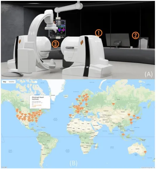
swine model. Arrows point to the catheters. ... 13 Figure 2.8 summary of the occupational hazards of exposure to x-ray for the Cath Lab crew ... 14 Figure 2.9 (A) Niobe Stereotaxis 1- remote magnetic navigation system 2- the workstation 3- the
working zone of the catheterization (B) the location of the hospitals that have installed this system (source: http://www.roboticep.com/) ... 24 Figure 2.10 (A) the additional gradient coils in the MRI tunnel [65] (B) the introduced concept for
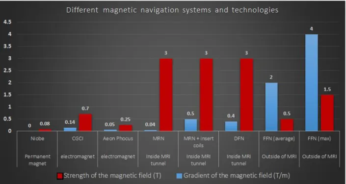
exploiting directional steering with FFN and (C) result of initial in vitro FFN experiments [69] ... 26 Figure 2.11 Comparison of FFN with other systems developed for magnetic navigation ... 27 Figure 2.12 Use of robots for patient positioning (A) Leoni (www.leoni-healthcare.com) (B)
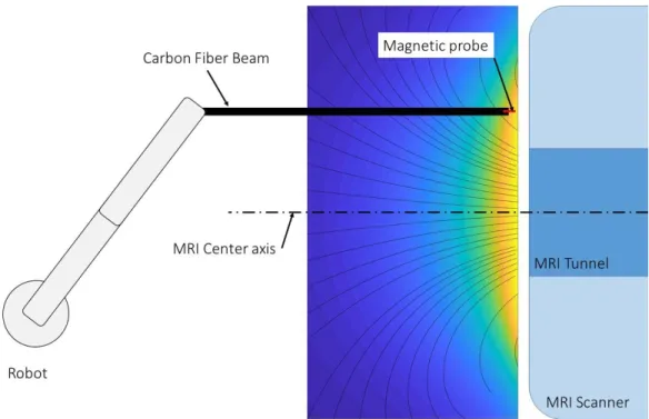
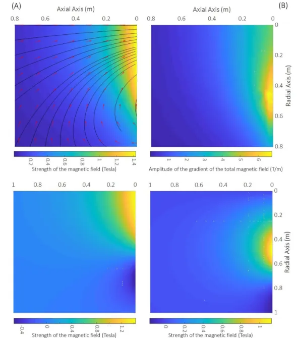
Examove 6F (www.exacure.com) (C) Cyberknife (https://www.cyberknife.com) ... 28 Figure 3.1 venue of FFN showing the MRI scanner, and the robotic patient positioning system . 30 Figure 3.2 Schematic plot of the set-up for sampling the magnetic fringe field ... 32 Figure 3.3 map of a radial plan of (A) total sum of the components of the fringe field of 3T
radial component (D) axial component of the fringe field. In (A) red vectors show the vector
field of the fringe field and the black lines are the lines of the magnetic field. ... 33
Figure 3.4 (A) vector field map of the fringe field and (B) the gradient force (vector field) and intensity of the gradient (heat map) the conditions described in 3.3.2. ... 36
Figure 3.5 Size of a cubic sub-volume in the fringe field in which the deviation in the direction of the magnetic field between the center and the corners of the cube is less than (A) 5 (B) 10 and (C) 15 degrees. ... 37
Figure 3.6 (A) local coordinate systems in sheared slab model [146] (B) size of the cube for 20 degrees deviation and (C) the curvature radius of the lines of the magnetic fringe field ... 38
Figure 3.7 (A) models used as an example and (B) example of exceeding nodes in centerline data ... 39
Figure 3.8 diagram of the remaining nodes from the centerline data through the progress of the step of elimination of the excessive nodes ... 41
Figure 3.9 (A) first shortest distance and (B) the second shortest distance of each node from the rest of the members of set S for the 3D model of the phantom ... 43
Figure 3.10 Schematic of the steps of planning the vascular trajectory from the centerline data .. 44
Figure 3.11 Schematic of defining the location and the orientation of the vascular trajectory in the coordinate system of the table ... 46
Figure 3.12 (A) Example of a segmented vascular path and (B) segmenting the trajectory ... 47
Figure 3.13 General order of the points in the maps of the fringe field ... 48
Figure 3.14 The limited working space of the robot for FFN experiments ... 50
Figure 3.15 examples for the modeling of different elements inside the venue for a sequence of FFN including the wall, floor, the robotic manipulator, and the table and MRI front face for the prediction of collision ... 51 Figure 3.16 steps of the robotic positioning of the table. *X-Y-Z coordinate system is shown in this
performed by reverse execution of the steps of moving the patient to the location of the
sequence of FFN. ... 53
Figure 3.17 Defined zones for the motion planning for robotic patient positioning (A) zone I and (B) zone II (the dimensions and the distances are not exact) ... 54
Figure 3.18 Schematic of the method of the registration by showing the relative position of different elements ... 56
Figure 3.19 (A) a DSA image taken during in vivo experiments of this work and (B) schematic representation of the steps of correction for registration ... 57
Figure 3.20 Example of the method for the correction of the error in the registration by use of DSA image ... 59
Figure 3.21 Main elements of the patient table for the robotic patient positioning ... 61
Figure 3.22 (A) the distribution of stress and (B) deformation ... 62
Figure 3.23 stress distribution in the carbon fiber beams under a uniform load of 750N ... 63
Figure 3.24 (A) the distribution of stress and (B) deformation ... 64
Figure 3.25 (A) the distribution of stress and (B) deformation ... 65
Figure 3.26 the system for feeding the guidewire ... 67
Figure 3.27 A sequence of FFN. Each line contains the coordinates to which the table has to be moved in for each step of the sequential patient positioning. The first and the last line are the HOME location. S and T are parameters related to the movement of the robot and the -1 value is set to use Linear Movement. ... 69
Figure 3.28 Schematic of communication between the server and different modules of the robot and the feeder system. ... 69
Figure 4.1 a picture of the general setup for in vitro FFN experiments ... 70
Figure 4.2 Priory steps of performing an FFN experiment ... 72
Figure 4.4 Robotic Positioning of the table for some examples of the sequences of FFN. In (A-D) moving the table partially inside the MRI bore and in (E-J) the table is entirely outside of the MRI scanner ... 74 Figure 4.5 result of FFN experiment with a 2D phantom ... 76 Figure 4.6 (A) the 3D phantom used for in vitro experiments and (B) the internal radius of different
parts of the phantom ... 77 Figure 4.7 (A) result of navigation of the custom microguidewire shown in (B) to different targets
of the 3D phantom and the red arrows point to the magnetic tip of the guidewire. (C) shows an example of the impact of large field-gradient-deviation on the tip of the guidewire (the crook) ... 78 Figure 4.8 (A) and (B) are two examples of using the vascular registration (black lines) on an x-ray image and locating the expected location of the tip of the guidewire (white squares). The markers were made by making holes on a plate of aluminum. ... 81 Figure 4.9 (A, C, E, and G) examples of the impact of using the pulling force applied on the tip of
the guidewire to insert the guidewire beyond the limit of the possibility of insertion manually from the other end of the guidewire (B, D, F, and H). The dashed ovals show the crooks at the distal of the guidewires. Red arrows point to the tip of the guidewire. ... 84 Figure 5.1 the layout of the rooms and the facilities for in vivo FFN experiment ... 88 Figure 5.2 the schematic layout of different components on the patient table for in vivo experiment ... 89 Figure 5.3 (A) a picture of the animal on the MRI table for the time of angiography and (B) shows
the markers ad the straps of immobilization on the table. ... 90 Figure 5.4 (A) 3D model of cerebral arteries of swine animal model and (B) the vascular trajectory
of the vessels ... 91 Figure 5.5 animal on the robotic patient table for FFN experiment ... 92 Figure 5.6 result of first in vivo experiment. Red arrows point to (A) the selected target of the
arrow points to a magnet that brock from the tip of the guidewire during the experiment and was trapped inside Rete Mirabile of the animal shown in the blue circle in (A). ... 93 Figure 5.7 example of a FFN sequence of positioning of the animal ... 94 Figure 5.8 (A) shows the detection of the circular markers with Hough Transform. (B) shows the
result of the registration of the vascular trajectory on a DSA image. (C) and (D) show the correction of the error in the registration of the vascular trajectory. White dashed lines in (A) are corrected of black dashed lines. (D) shows the binarized DSA image and the white dashed lines shows the vascular trajectory after applying the transformation to correct for the error (Details of the method is presented in chapter 3). ... 95 Figure 5.9 result of the second in vivo experiment on animal model 2. (The red arrow in X-ray
image (B) shows the tip of the guidewire place at the selected target (red circle) in (A) MRI image. (A) shows that the arteries of the animal were not visible in the MRI image. The gray area in (B) is related to an instrument from a separate experiment. ... 96 Figure 5.10 (A, and B) show examples that the insertion of the guidewire without applying a pulling
force at the tip of the guidewire was not possible and the distal of the guidewire (shown in dashed ovals) crooked. The gray area in both images is related to an instrument used for another experiment. ... 98 Figure 6.1 envisioned mechanism of deformation of the spring tip of the guidewire during retrieval
through the catheter (A) bending inside the catheter and (B) unwinding. ... 100 Figure 6.2 the interaction of spring with different configuration with the external magnetic field.
(1) is tightly winded and L/D > 2. (2) is tightly winded and L/D ~ 1 and the orientation of the spring changes with the strength of the external magnetic field. (3) is spring with a gap between its turns and it is perpendicular to the direction of the external magnetic field. .... 102 Figure 6.3 (A – E) shows results of in vitro FFN experiment with a spring at the tip of the guidewire
LIST OF SYMBOLS AND ABBREVIATIONS
Cath Lab Catheterization LaboratoryCE Conformité Européene CNC Computer Numerical Control DOF Degree of Freedom
FDA Food and Drug Administration Fr French
FOV Field of View ID Inside Diameter IP Internet Protocol IV Intravenous
MRI Magnetic Resonance Imaging OD Outside Diameter
RF Radio Frequency SNR Signal to Noise Ratio
TCP Transmission Control Protocol TE Echo Time
LIST OF APPENDICES
Appendix A Developments in summary ... 120
Appendix B Thin plate spline interpolation ... 121
Appendix C Formulation of magnetic gradient force ... 122
Appendix D Schematic of the method of vascular registration (Calibration) ... 123
Appendix E FFN app (screenshots) ... 124
INTRODUCTION
The vascular system of humans consists of a complex and interconnected network of blood vessels that spreads across the body to provide nutrition and oxygen for the living cells metabolism. The range of the diameter of the blood vessels varies with 3000-fold between Aortas as the largest artery with an average diameter of 25000 microns to capillaries with a few microns of diameter [1]. Vascular catheterization is the medical procedure of placing a catheter – a tubular and flexible medical device – inside a vascular path to administer a material such as the embolizing agent or place a device like a stent at a desired location within the body [2, 3]. Medical procedures that are based on the catheterization are considered to be a less-invasive alternative to the medical treatments such as surgeries [4-7] or insertion of a needle [8, 9] to perform a certain therapy. Placing a catheter in blood vessels enables to deliver a therapeutic agent to the desired location inside the body through a vascular rout instead of performing surgery to access the site of the problem or toxication of the whole body similar to the chemotherapy. Catheterization of hardly accessed sites inside the body and placing the catheter instrument in the narrow blood vessels and lessening the arduousity of manual catheterization by raising the level of autonomy of the procedure to make it an easy operation to implement would enhance the quality of current catheter-based procedure while enable introducing novel treatments.
Surgery is a traditional approach to treat the problematic area inside the body[10-12]. The robotic system of Da Vinci [13, 14] was developed to minimize the invasiveness of certain surgeries by performing the operation through the insertion of the robotic endoscopic hands and camera inside the body through small punctures made on its surface to minimize the pain and the post-operation complications for the patients while facilitating the operation by adding robotic precision. Insertion of a needle into the body had also been investigated as a solution to minimize the invasiveness of the surgeries when the treatment requires administration of a drug or ablation of a bulk of malignant cells inside the body [15]. Inserting needles for the RF or cryogenic ablation of cancerous tumors inside the liver [16], prostate [17], pancreas [18], etc. have already translated to the clinical setting. A recent project called EDEN 2020 aims to develop a method for local therapy and drug administration inside the brain based on the insertion of a bioinspired deformable needle into the brain tissue as a substitution for the surgeries [19]. Radiation therapy uses ionizing radiation for the destruction of malignant cells while eliminating the need for access to the problematic site[20].
In focal ultrasound surgery, the energy for damaging the malignant cells is concentrated at a focal point through using its specific transducer allowing to perform a focal surgery at a deep location within the body without harming surrounding healthy tissues[21].
Catheter-based treatments are investigated for the development of less-invasive alternatives to traditional treatments in cardiology[22], interventional oncology[23], and treatment of the vascular diseases[3]. Manual or robotic catheters can enter the within the heart from the path that blood gets inside of it. Then, operation inside the heart chambers without affecting the functioning of this vital organ by passing through its valves and the septum wall to provide access to interior surface and tissue of the heart becomes possible. It has had a significant impact on developing novel minimally invasive methods of diagnosis and treatment in the cardiology[24]. Diagnosing the vascular diseases in coronary arteries, cerebrovascular arteries, and peripheral arteries by the injection of a contrast media (CM) into the vessels and use radioscopy to detect occlusion or abnormality that impairs the circulation had been used for decades, and currently, catheters are developed for intravascular imaging based on Optical Coherence Tomography and Ultrasound technologies[25]. Use of the catheters to access the diseased site in the peripheral arteries is now a clinical alternative to vascular bypass surgery in different branches of Aorta in the abdomen [2], coronary arteries[26], carotid[27], etc. Angioplasty is a term used to describe the procedure of widening an obstructed blood vessel and it is done by insertion of a balloon catheter with an inflatable part at its distal to widen the occlusion in the vessels. For a more long term – and effective – treatment, placement of a stent – which is a tubular wired structure – at the problematic site in the vascular system is utilized to treat the cause of occlusion by eluting the drugs attached on the stent which is in direct contact to the cause of occlusion [26, 28, 29]. The need for the removal of stents from the body has led to the development of biodegradable stents[30, 31]. Arrhythmia in the functioning of the heart can be diagnosed by Cardiac Electrophysiology (EP)[32, 33] and treated by focal ablation [34]. The device for collecting the electrophysiology signal from the internal surface of the heart tissue or performing the ablation of the tissue of the heart to regulate the heartbeat rhythm is integrable into a catheter that operates within the heart [35].
Interventional oncology is another vast place for using the catheter.s The first practice of chemotherapy was done by administration of a drug based on the mustard gas agent to the body of the terminally ill patients to treat cancer[36]. As an alternative to chemotherapy which relies on
systemic circulation of toxic drugs across the body, one approach is Transarterial Chemoembolization (TACE) that is based on blocking the blood vessels that supply blood to the solid tumors by local administration of embolic agents through a catheter priory placed in a desired blood vessel [9, 15, 23]. Currently, TACE is counted as one of the options for the treatment of Hepatocellular carcinoma cancer, which is the most common type of liver cancer. Unique vascular anatomy of the liver allows performing full embolization of the hepatic artery or its major branches to perform TACE. However, Super-selective catheterization of the arteries that feed the tumors is required to achieve better treatment result[37] as TACE is applicable to any type of cancer with a solid tumor. This need also has led to the development of drugs and methods for non-systemic delivery of the therapeutic agents to the tumors [38-42]. So, if it is difficult to place the tip of the catheter as close as possible to the tumor, these new technologies enable to navigate drugs along the path between the point of injection – or the tip of the catheter – to the tumor to enhance the efficiency of the therapy. All of the catheter-based procedures discussed here are the clinical options for the treatment of the major causes of mortality and illness across the world including cardiac arrest[43, 44], stroke[45], and cancer[46, 47].
Developing new devices that can operate inside bodily environments to perform a local diagnosis or treatment have been actively investigated for applications in medicine [48]. Development of new materials and robotic medical agents is a growing field in biomedical engineering domain [38-41, 48-59]. Currently, nano/micro/mili scale synthesis or biohybrid robotic systems with different modes of locomotion[50, 51] are developed for operation inside the body and various methods of actuation including the magnetic field [39, 55, 57, 60], light[61], ultrasound[62], biological motors[63, 64], and chemical propulsion [65] have been exploited for the mobility of the devices. Drug delivery to the hypoxic zone of the solid tumors has been realized by dispatching a swarm of bacteria with Aero-Magneto taxis capability that propels with its flagella and is sensitive to the gradient of the oxygen concentration and can rotate by the magnetic field [66, 67]. Helical micro swimmers have been investigated to operate in various bodily fluid for imaging and treatment purpose [55, 57, 58]. Soft-bodied small-scale robots are emerging to answer the problems regarding the mobility of the robots to pass obstacles to enable moving in different environments in the body[50]. Shapeshifting soft-bodied micro-robots with the high motility in complex channels can swim in the viscous flow are developed to reach remote locations [51]. All of these advances
promise to enhance life quality by introducing novel medical treatments. Mainly, these advances require vascular catheterization to deliver the agent or device to the desired target inside the body [68].
No wonder that vascular catheterization is reshaping the therapies, and the scope of the catheter-based operation is expanding. However, endovascular catheterization is a growing field and acquiring the skills required to perform a procedure is a dynamic process which highly depends on the experience of the practitioner [2, 3, 69]. Tackling this issue has been confronted by developing robotic systems for catheterization [70-75]. Application of robotic system in the catheterization had been successful for applications in cardiology, and many clinics across the world have adopted robotic systems for the cardiac interventions [4, 7, 74-77]. However, developing robots for selective and super-selective navigation of the catheters in the complex vascular systems is still in its infancy as the most prominent robotic systems for vascular catheterization with FDA approval – e.g. Amigo robotic catheter and Magellan (Hansen Medical) – are capable of targeting major peripheral arteries while the caliber of the catheter does not allow further advancement in the vascular system.
With applications in the interventional oncology or the treatment of the vascular diseases, roboticization of vascular catheterization can facilitate reaching to a desired – and even remote – site in the vascular system. By passing multiple branches to access a location deeper inside the vascular system, the tortuous blood vessels become narrower[1]. It requires miniaturization of the guidewire instrument and the systems for actuation in order to target narrower vessels[69, 73]. Miniaturization of the instrument results in the decrease of its stiffness until steerability becomes unpractical while pushing the instrument at the insertion site to counteract the opposing friction forces being amplified by the added surface in contact against the vessel walls and caused by the bending of the instrument [73]. Applying magnetic torque on the tip of the catheter has been used in different applications for steering catheters [71, 74, 75, 77]. However, miniaturization of the catheter and reducing the stiffness to target smaller vessels, adds new complexity for insertion of the device[69, 73]. Therefore, applying a pulling force on the tip of the guidewire is considered as a way to resolve this problem and the magnetic gradient force was introduced to overcome this challenge. In [69], the gradient of up to 0.5 T/m was used for steering of a microguidewire in the peripheral arteries of a rabbit model. Fringe Field Navigation (FFN) was introduced to exploit the
gradient (up to 4T/m) of the magnetic fringe field of the clinical MRI scanners for the navigation of the guidewires[73]. The strong pulling force provided by the fringe field was the mean to enable insertion of the guidewires with a soft and floppy distal in the narrow vessels.
The initial experiment of FFN demonstrated the possibility of steering microguidewires in multibifurcation models. However, the initial experiments had limitations. The MRI Fringe Field is a static field and so providing directional actuation requires relative 6 DOF positioning of the patient and the magnetic field. While the MRI scanner is way heavier than the patient, positioning of the patient by a robotic system is proposed as the solution to provide the required directional actuation. The first limitation of the initial FFN experiment was the lack of the essential 6 DOF patient positioning [73, 77]. Second, the experiments were limited to using the center axis of the MRI fringe field which the direction of the magnetic field lines and its gradient. FFN is proposed to navigate microguidewires with a magnetic body attached at its tip in the 3D vascular systems. Another problem along the way of FFN project is the retrieval of the guidewire through a small catheter – a microcatheter [69]. This problem arises from the fact that retrieving a microguidewire which has a magnetic tip with a size larger than the diameter of the shaft of the guidewire requires a larger caliber of the catheter. It may lead to the impossibility of using a microcatheter for a procedure.
1.1 Contribution of this project
The Main goal of this project was to investigate if a pulling force applied on the tip of a guidewire enables to navigate a microguidewire to a location beyond the limits of traditional approaches or the methods that solely rely on the bending the tip of the instrument. In other words, this project aimed to demonstrate that a pulling force applied on the tip of a floppy and soft microguidewire allow advancing the instrument in narrow vasculatures. In FFN, providing this force at a remote location within the vascular system is provided by exploiting the gradient of the magnetic fringe field around the MRI scanners. In fact, this work tries to investigate if FFN can push the boundaries of robotic catheterization in targeting smaller vessels. In parallel, developing a robotic method to enhance the level of autonomy and reduce the need for the experience from the practitioner had high importance in this project.
This work reports on the developments to implement the FFN by six DOF robotic positioning around an MRI scanner and the results of the navigation of microguidewires. Chapter 3 presents developments, either materials or methodologies, to perform FFN experiments. The developments aim to increase the level of the autonomy of the procedure. In Chapter 4, results of in vitro experiments of FFN are presented for the (1) navigation of a guidewire through multibifurcation and narrow vascular paths, (2) demonstrate the impact of the magnetic gradient force to insert a guidewire beyond the limits of manual insertion, (3) the possibility of the miniaturization of the instrument in FFN, (4) and robustness in FFN against error in the 6 DOF patient positioning. In Chapter 5, the results of in vivo experiments of FFN on a swine animal model to navigate a microguidewire in cerebral arteries. Also, the impact of the pulling force provided by the fringe field to insert microguidewires in narrow blood vessels is demonstrated in vivo as well. Chapter 6 presents the concept of a new magnetic body for the tip of the guidewire as the basis of developing a deformable magnetic tip which is not a permanent magnet and can saturate in the fringe field, to facilitate the retrieval of the guidewire through the smaller catheters. General discussion, conclusions, and recommendations for the future work on FFN are presented in chapters 7 and 8.
LITERATURE REVIEW
Endovascular interventions are reshaping the methods and approaches of treatments and the scope of the catheter-based procedures are broadening by introducing novel minimally invasive methods of treatment and diagnosis. The main categories for the application of the catheter-based interventions are in the cardiac intervention [4, 78], diagnosis and treatment of the peripheral vascular diseases[2, 3, 6, 11, 78-80] and interventional oncology[9, 15, 23]. Conducting a successful intervention requires different knowledge, skills, and experience. Adapting eye and hand to the fluoroscopic image (fluoroscopy-eye-hand coordination), prediction of the interactions between the guidewire and the vessels (particularly at the site of the lesions), choosing the right combination of the catheter and the guidewire, and knowing the limits of an intervention to determine the end of a procedure, are some of the necessary endovascular skills. To prepare the interventionist to perform an intervention, development of the catheter-guidewire skills has high importance. Acquiring the skills relies on the experience of the practitioner and the number of interventions they have participated is considered as a criterion to evaluate their qualification to perform a specific procedure. To emphasize the importance of experience in performing an intervention, Table 2.1 provides examples on the recommendation of different endovascular societies on the number of the cases it takes for a new physician to qualify to perform an endovascular intervention[2].
Table 2.1 number of the interventions when an interventionist qualifies
SIR SCAI ACC AHA SVS
Angiogram 200 100/50a 100 100 100/50a
Intervention 25 50/25a 50/25a 50/25a 50/25a
a As primary interventionist.
Abbreviations: SIR, Society of Interventional Radiology; SCAI, Society for Cardiac Angiography and Interventions; ACC, American College of Cardiology; AHA, American Heart Association; SVS, Society for Vascular Surgery.
2.1 Brief about the catheterization procedure
In this section, a concise introduction of the steps of catheterization is presented. These explanations are supported with the examples from in vivo experiment that was performed for this
project. A catheterization procedure begins with the preparation of the patient. It includes putting the patient under anesthesia (local or general) and intubation of the respiratory tract. After preparation of the patient, the initial step in a catheterization procedure is accessing the vascular system. This step begins by making a puncture on the skin to open a way to insert the catheter device in a major blood vessel. There are different vessels considered for accessing the vascular system including femoral artery, brachial artery, subclavian artery, and carotid artery. The femoral artery which passes at the groin is the most common artery for vascular access. The access can be performed retrogradely or antegrade depending on the location of the target. For instance, antegrade access to the femoral artery is required for intervention in the popliteal artery which is in the lower limbs while retrograde access is needed for entering the device in the Aorta. A wrong decision for the access can make a simple intervention difficult, or make a difficult intervention impossible. Figure 2.1 represents a schematic example of the concept and the direction of the vascular access for an intervention. Finding the right site of the puncture on the skin is important to reduce the damage to the tissue of the patient and related complications. Some of the complications regarding the vascular access are bleeding either minor or major, perforation of the vessel, or infection[81-83]. Different external landmarks such as features on the skin or bony landmarks or landmarks that are visible under radioscopy like the location of the head of the femur bone are considered as the ways to find the site of the puncture. Radioscopy is the common approach to find the optimal location of the site of puncture. This approach was also used to find the site of the puncture in in vivo experiments in this work. Figure 2.2 shows an example of an
X-Figure 2.1 Schematic example of (A) retrograde and (B) antegrade access to the femoral artery (B)
ray image taken for finding the location of the puncture for access to the femoral artery in a swine model by finding the head of the femur. Use of ultrasound imaging (Doppler ultrasound) to guide the procedure is another approach for image-guided vascular access[84].
After finding the artery, insertion of a needle inside it opens the way into the vascular system. Backflow of the blood out of the needle is the way to validate that the needle is inside the artery. Then, a guidewire passes through the needle into the artery. This step is followed by withdrawing the needle and insertion of the sheath over the guidewire into the accessed vessel. The sheath is used to provide secure access for the insertion of the other devices (catheters and guidewires). Inserting a dilator into the sheath is also a common practice to stabilize the vascular access [2]. After access to the vascular system by placing a sheath, it is the time for the guidewire-catheter operation to reach the desired target. The catheter and the guidewire are complementary to each other. The whole procedure to navigate a catheter into the location of the target in the vascular system is done by the use and exchange of different guidewire and catheters during a procedure. There are different criteria in choosing the right combination of the instruments. Length, diameter, coating, stiffness and the shape of the tip are the basic features to choose the right device for an intervention. Some other features that distinguish guidewires from each other are variation in the Figure 2.2 Example of an X-ray image taken for localization of the site of the puncture for access
stiffness of the shaft along its length, high torque transfer between the shaft and the tip, or length of the floppy distal of the guidewire. The material of the guidewire is another important criterion especially for its visibility under X-ray or in a more advanced application, its compatibility with magnetic resonance imaging in MR-guided interventions[85, 86].
The shape of the tip of the guidewire is an important feature that enables steering into bifurcations. Certain shapes or hooks at the tip are considered to facilitate specific interventions and to facilitate insertion into a vascular branch. When a guidewire has reached near the location of a bifurcation, specific shapes of the tip would be prone to advance easier into the desired vascular branch. Same as the guidewires, catheters are developed with the different shape at their tips for the navigation into different vascular branches. Figure 2.3 shows some different selective catheters in action. Also, various types of catheters exist which their characteristics differ from each other based on their application. Catheters for the navigation, catheters for angiography and catheters that are used for exchanging devices during an intervention have specific features depending on their application. This variation in the type of the devices and the will of the physicians in choosing a combination of the catheter and guidewire based on their experience is a reason for considering the endovascular skills to be a dynamic process.
Size of the diameter of the catheters is defined in French Scale (Fr) and each 3 Fr is equal to 1mm. Guidewires and catheters are produced with different diameter, and currently, micro-catheter/guidewire devices are widely in use. The devices with a smaller size, e.g., the guidewire with a diameter of 0.014-in, are used for navigation inside narrower arteries like coronary arteries
which its diameter is between 1 to 4 mm[2]. It is because using a larger caliber of the guidewire or catheter can limit the blood circulation in narrow arteries, or larger devices can induce higher mechanical forces on the vessel walls. To improve the blood circulation, administration of heparin (systemic) to reduce the blood viscosity with more impact on the plasma’s viscosity and to reduce the chance of thrombosis is also considered[2, 87].
Figure 2.4 Example of the orientation of the cerebral arteries in a swine animal model. The long arrow points lingual artery, the short arrow points to the external carotid artery
A consideration regarding fluoroscopy-guided intervention is that the 3D vascular structure is projected on a 2D image. Understanding the spatial direction of the vessels on a 2D image requires a knowledge of the vascular anatomy. Figure 2.4 is an example of two different views of the X-ray imaging of the cerebral arteries of a swine animal model performed during in vivo experiments of this work.
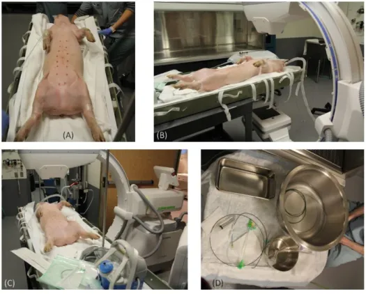
Figures 2.5 and 2.6 show images to illustrate some of the concepts and steps for a catheterization procedure. The images are related to the procedure of catheterization of the common carotid artery of a swine animal model. Figure 2.5.A shows the animal prepared for the surgeries and the catheterization after putting under general anesthesia. Figures 2.5.B and 2.5.C show the animal on the patient table under the X-ray, and Figure 2.5.D shows the catheter and guidewires that are sterilized and prepared for the intervention. In Figure 2.6, (A) is the step of puncturing the skin to find the femoral artery shown in (B). Insertion of a needle into the femoral artery and introducing a guidewire to keep the vascular access is shown in (C) and (D). Then, the needle is withdrawn, and the sheath is introduced (E), the initial guidewire (F) and the dilator (F) are removed to insert the guiding guidewire (H) inside the body. Then the guiding catheter is inserted over the guidewire (I), and the location of the access is secured (H).
2.1.1 Hazards and complications
As mentioned before, fluoroscopy-eye-hand coordination is an essential and important skill that an interventionist has to develop during the training. It is because the visualization of the devices and the blood vessels inside the body is most often done under fluoroscopy and navigation is done by manually turning and insertion of the guidewire. Blood vessels are invisible under X-ray as shown in Figure 2.7. To make the visible in radioscopy, interventionists administer contrast media (CM) into the blood vessels through the catheter, and this material visualizes the blood vessels under the x-ray. The common types of CMs are iodine and barium based. Both of the exposure of the body to ionizing X-ray radiation and intravenous administration of CM[88] could leave adverse effects on the patient. The CM may induce the nephrotoxic effect on the kidney and the renal function[2, 3]. Limiting the time and intensity of the x-ray exposure to the patient and dosage of the administered CM is beneficial for the health of the patient.
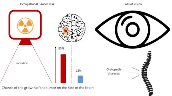
Exposure to x-ray is also an issue for the team of the intervention as they are periodically exposed the hazardous radiation. A study on the interventional physicians with a brain tumor found that in 85% of the patients, the tumor has been developed on the side of the brain which typically faces Figure 2.7 Examples of showing the catheters under X-ray in (A) Aorta and (B) carotid artery of
the x-ray source[89]. Loss of vision is another side effect of the x-ray on the crew of the intervention. It is found that 50% of the interventional cardiologists and 41% of the nurses and technicians of the Cardiac Cath Labs has significant posterior subcapsular lens changes[90]. To limit the side effects of x-ray exposure, the crew protect themselves by wearing a lead apron that blocks the x-ray. However, the heavy protective apron is a cause of ergonomic issues for the personnel[91]. Regarding this issue, a study found that 49% of the cardiac interventionists have suffered orthopedic injuries as a direct result of their work[78]. Figure 2.8 summarizes the major occupational hazards for the crew of the Cath Labs due to being exposed to X-ray radiation. While endovascular intervention is counted as a less invasive alternative to the surgeries, different complications with various prevalence and mortality rates are associated with them. These complications cause discomfort and health problems for the patient and can prolong the period of healing or even lead to death. The most common cause of the complications is stated to be the mechanical interactions between the catheter and the interior wall of the blood vessels. Arterial spasm, hemorrhage, and occlusion followed by the vascular trauma are some of the complications related to the mechanical interactions and forces applied to the vessel walls. Nephropathy and renal failure are complications related to the usage of contrast media. Improvement in the design of the catheter devices to passively protect against these complications is a common way of reducing the likelihood of the occurrence of these complications[2, 3, 81].
2.1.2 Selective Catheterization
Vascular catheterization is coded (catheter placement code – CPT) as selective and non-selective procedures[92]. Non-selective catheterization is the placement of the catheter in the accessed vessel, for example for the case of aortic aneurysm repair [2]. Selective catheterization is the placement of the catheter into a branch of the accessed artery, e.g., one of the main branches of Aorta. Selective catheterization permits focused arteriography and delivery of the therapeutic devices. Improving the technologies in endovascular intervention allows placement of the catheter in all the branches of the Aorta. The meaning behind this technological advancement is the development and availability of a wide array of catheters and guidewires with various specifications as well as technics for the catheterization of different vascular branches. Major peripheral arteries of the Aorta are iliac, femoral, renal, superior mesenteric, celiac trunk to the hepatic artery, subclavian, and carotid artery. The main reasons for performing a selective catheterization are either for diagnosing or treatment of the arterial diseases such as the diagnosing of vascular occlusion with an angiogram[82] or stent placement in the carotid artery[27]. An essential consideration in selective catheterization is to insert the guidewire far enough into the vascular branch (bury the guidewire) to minimize the risk of dislodging the guidewire during the step of the insertion of the catheter[2]. Different factors are considered in choosing the right catheter or guidewire to navigate into the vascular branches. For example, a lesion at the bifurcation or the branch of the vessel influence this decision. In the end, the interventionist chooses the type of guidewire-catheter and the strategy of the intervention.
2.1.3 Super selective catheterization
Placement of a catheter in the branches of the accessed vessels is called selective catheterization. Advancing the procedure by further insertion of the catheter and passing more bifurcations is called superselective catheterization. Vascular diseases are not limited to happen in the accessed vessel or its main branches. For instance, the occurrence of an aneurysm or occlusion of the cerebral arteries which is a cause of the stroke can take place in any cerebral artery. By the increase of the number of the bifurcations between the Aorta and the problematic site in the vascular system, the blood vessel becomes narrower, and access would become more challenging to perform. However, providing an efficient and long-lasting therapy for the patient with less-invasiveness makes
endovascular treatment approach an effective treatment option with less-complications for the patients.
Superselective catheterization is also used in interventional oncology and repair of vascular anomalies. Superselective catheterization of the branches of the superior mesenteric artery and the hepatic artery is performed for super selective angiogram[93] or transarterial chemoembolization (TACE) of blood vessels that supply blood to a problematic site[94]. In TACE, embolization of the blood vessel that supplies the cancerous tumor while avoiding blockage of the other arteries is essential and ideal. Some examples of using the super selective catheterization in the abdominal region are the treatment of polycystic liver disease[95], Hepatocellular Carcinoma[23], aneurysms[96], pancreatic angiogram and embolization[97], and Colonic embolization[98]. Catheterization of the ophthalmic artery which is a branch of the internal carotid artery is performed for the treatment of retinoblastoma[99]. Superselective catheterization of the branches of the renal artery[100], and iliac artery[101, 102] are also other examples of super-selective catheterization. In the end, the importance of superselective targeting in the vascular system is to increase the efficiency by local access to the site of the disease.
2.2 Advancements in drugs and delivery
Introducing the cytotoxic concept to the oncology dates back to the period after world war II which mustard gas agent was used for the treatment of lymphoma[36]. Since then, the development of new drugs and methods continued in order to develop an effective method with fewer side-effects for the patients. TACE is a treatment option in oncology which aims to deprive the cancerous cells of the nutrition for their longevity by blocking the blood vessels that feeds them while degradation of the embolic agents releases the chemo drugs into the tumor to enhance the efficiency of the therapy [103]. Currently, different types of embolic agents are developed in the forms of microspheres[42], and injectable coils [104]. Administration of these drugs requires catheterization of the arteries that feed the cancerous cells to avoid blocking the vessels that feed the healthy cells. Catheters provide a direct exclusive route from the syringe that contains the drug to the desired location. This local drug delivery is highly advantageous over the chemotherapy which relies on the systemic drug delivery[39, 40]. TAE or TACE is currently a treatment option for cancer in the liver because of its unique vascular anatomy as the liver has two blood supply.
Local delivery of the drug is important to increase the quality of therapy and reduce the side effects. In TACE, the embolic agents flew with the systemic blood circulation after releasing from the tip of the catheter. Navigation of the drugs at the bifurcations to selectively deliver them to the target has become a novel field in biomedical engineering that comprises the development of the navigable drugs and the method for the navigation. Using magnetic actuation is a promising method for the navigation, and the development of the magnetically navigable drugs and the methods of navigation have been investigated as well. Regarding the drug, the development of the micro magnetic particles (MMP) as an embolic agent is already achieved and material with different size and magnetic characteristics are developed[42, 105]. Methods for the navigation have been developed based on using the gradient of the MRI scanner dubbed as magnetic resonance navigation (MRN) to apply a directional force on the particles[105, 106]. The magnetic gradient of the MRI scanners is limited to 40mT/m, so Dipole Field Navigation which is based on distorting the uniform magnetic field inside the MRI scanners by the insertion of a magnetic body inside the MRI bore was introduced to produce a higher gradient of up to 0.4T/m and beyond for the purpose of navigation [107]. These methods aim to deliver the magnetic therapeutic agents to the desired target through a vascular route from the point of release of the drug which is the tip of the catheter. Placing the tip of the catheter closer to the target helps to increase the efficiency of these methods therapy.
The methods based on embolization aim to kill the cancerous cells by starving them by closing the passages to the tumor. A big challenge in oncology is the delivery of the drugs to the hypoxic regions within the tumor. A recent breakthrough reported the possibility of targeting the hypoxic region in the solid tumors by use of aero-magneto taxis feature of a certain bacteria that can also carry a drug loaded on its surface. Catheterization of the blood vessels that go to the tumor is a way to increase the delivered amount of the dose of the injected drug to the tumor[66, 108].
Another research has introduced the possibility of passing the blood-brain-barrier to deliver magnetic particles to the tissue inside the brain by use of high frequency reversing magnetic field and use of the hyperthermia effect to kill the cancerous cells inside the brain. This work is extended to the case of passing the blood-retinal-barrier. Application of this method is also in the local drug delivery inside the brain. Catheterization of the blood vessels that reach the desired target for the delivery of the drugs is essential for this application to increase the amount of the drug delivered
to the site of the tumor while minimizing the chance of damaging brain cells due to hyperthermia effect[109, 110].
2.3 MRI-guided catheterization
MRI offers different advantages in comparison with other medical imaging modalities. First, no ionizing radiation is used in MRI. It is advantageous for the patient as well as the interventionists. MRI image allows to orient the slices in 3d volume to see the vascular anatomy from different angles. The dosage of Gadolinium CM used in MR angiography is less than the Iodine CM used in fluoroscopy which may cause nephrotoxicity. More importantly, MRI provides soft-tissue contrast to distinguish between different tissues and blood vessel and no harmful effect from 1.5T and 3T MR imaging on the patient has been reported. These advantages have made endovascular interventionist interested in developing MRI-guided methods for catheterization. In the past decades, research on developing methods and devices to perform an MR-guided endovascular intervention have been actively pursued [85, 86].
Safety of a new type of intervention has to be at first validated with experiments on the animal models. In the development of MRI-guided endovascular interventions, a vast body of the work is reported in the guided catheterization in an animal model. Different cases of fully MRI-guided catheterization of hepatic artery in swine[111], stenting of aorta and filter placement in vena cava vein in swine[112], real-time MRI-guided intervention of renal artery for angioplasty and stent placement[113] and in-vivo visualization and tracking of an active catheter in carotid[111] and renal artery[114] in the swine animal model have been reported are some of the examples of MRI-guided interventions.
Results of successful cases of MRI-guided endovascular interventions on human have also been reported in the last two decades. In 1997, the first case of MRI guided endovascular intervention in a human was reported[85, 115]. In this work which aimed to navigate a catheter in the basilica vein of a human, passive tracking of the catheter with MR imaging was performed for guiding the intervention. In [116], results of MRI-guided cardiac catheterization in children and adults are reported. Also, MRI-guided cases of endovascular intervention in human for angioplasty of femoral artery stenosis[117], and some other examples [85] are reported as other cases of using MR imaging to guide an endovascular intervention.
2.3.1 Devices
The high strength of the magnetic field, the high gradient of the MRI fringe field and the RF waves used in magnetic resonance imaging makes it challenging to develop systems and devices to work in an MRI facility. These factors, especially the compatibility of the device with MR imaging, have impacted the progress in the field of MR-guided endovascular interventions. In fact, the progress of MR-guided interventions has not yet reached to a level appropriate for clinical translation due to the complexity of the development of MRI safe and compatible devices with appropriate mechanical characteristics for endovascular interventions [118-120]. Use of metals for the cores and/or braiding in the catheter and guidewire instruments are common in endovascular devices to provide adequate torque/push/pull-ability as well as radioscopy visibility. The metallic alloys like nitinol that use of them in the fluoroscopy-guided intervention is safe are conductive of electricity or magnetic permeable. The Problem with the use of conducting materials in MR-guided intervention is the heat induction in the instrument from the radiofrequency pulses of MR imaging. Besides, deterioration of the MR image from the susceptibility artifact is another obstacle in use of the metallic alloys, even in a limited quantity, in the devices for MRI-guided intervention. Limiting the use of metallic material to develop MRI-compatible devices leads to lower torsional and bending stiffness and so steerability of the device which leads to the difficulty of the navigation [116]. Based on the literature, and the survey performed by the author of this thesis on the website of the major producers of the interventional devices, no catheter or guidewire instrument is available that has received FDA approval for MR-guided intervention[118].
Many groups and companies have developed MRI-compatible products each designed for specific intervention like cardiac electrophysiology, renal and cardiac catheters, catheters for biopsy and catheters for tracking but only a few of these productions are suitable for translation to the clinical use. The first guidewire that featured conditional MRI-compatibility received CE mark in 2012. Use of PEEK in developing MRI-compatible guidewires as an alternative to the nitinol is common, and fiber-reinforcement of the guidewire is considered as a solution to improve the mechanical properties of the guidewires. However, guidewires that are reinforced with fiberglass are prone to disrupter during an intervention. The use of nylon and peek have been suggested for braiding of the catheters to make MRI-compatible catheters with improved mechanical characteristics. In
general, the state of the MRI-compatible endovascular devices is still behind the state of translation to the clinical use, and research on developing appropriate devices has to continue[118].
2.3.2
Passive and active i
magingThe method of imaging and tracking the device inside the body is an essential part of an MR-guided intervention. Real-time MRI for tracking of the devices inside the moving anatomy with proper resolution without any danger for the patient is the ideal condition. One approach which has been widely investigated in different work is incorporating MRI-visible markers along the shaft of catheter or guidewire[85]. These markers either reduce or amplify the MR signal to make a difference in the contrast of the image. It has been done by the use of paramagnetic rings attached to the device[115] or administration of paramagnetic contrast agent in the lumen of the catheter[121]. These approaches do not require additional hardware or post-processing of the image and are called passive tracking. Another approach, called active tracking, is done by inducing an electrical current in a circuit integrated to the catheter to generate a local distortion in the magnetic field that results in voiding MR signal at the location of the distortion. In these methods, induction of current can be synchronized with the imaging sequence to differentiate between the images created in two switching states of ON/OFF to track the device. Methods based on integrating the device that incorporates a small RF coil with the MRI for tracking and profiling the RF signal has been proposed[85].
Also, XMR intervention suites which integrate the MRI and X-ray modalities is another solution to fuse MR image with its soft tissue contrast feature with X-ray imaging to guide and intervention[122]. These intervention rooms allow co-registration between the two imaging modalities and 3D/2D image registration for image-guided interventions by use of a robotic table for transferring the patient between the two imaging modalities[123].
2.3.3 Occupational considerations for MRI-guided intervention
The isocenter of the MRI scanners that contains the field of view of the imaging is at the center of the bore. MRI scanners are can be categorized regarding the length of the tunnel in the two groups of long and short bore scanners. The first group has a bore length of about 1.7m (e.g. Magnetom Skyra, Siemens) and this length for the second group is about 1.25m (e.g. Magnetom Espree,
Siemens). The common size of the diameter of the closed bore MRI scanners is 0.6m or 0.7m. These conditions physically limit the interventionist to access the patient and it may lead to ergonomic injuries. Open Bore MRI scanner improve this drawback by providing more working space and freedom for the interventionist, but this type of scanner suffer from the lower SNR for imaging due to lower strength of the homogenous magnetic field for the imaging[124].
2.4 Robotic catheterization
The role of vascular catheterization in medicine is expanding. Clinicians use the vascular catheterization for the different purposes of diagnosis and treatment of cardiac, and vascular diseases or in oncology. Cardiac diseases, coronary diseases and aneurysm in cerebral arteries which is a cause of the strokes are among the top causes of death due to a health issue. TACE is an efficient method of treatment of cancer with a solid tumor it is in use for the treatment of a specific type of liver cancer. There is a high potential of using TACE for treatment of cancer types with a solid tumor, and one obstacle is performing superselective catheterization of the blood vessels. All being said to clarify the role and impact of vascular catheterization in medicine. However, limitations including the high dependency on the experience of the practitioner and the adverse impact of the x-ray exposure are the obstacles of widespread use of less-invasive endovascular treatments for different cases. Introducing the robotic methods to the field of vascular catheterization have been considered as a way for the improvement first by developing mechanisms of steering and second letting the interventionist to control the device in a safe workstation away from the X-ray imaging. Domains covered in the field of robotic catheterization includes the development of steerable catheters and the mechanisms of actuation [70, 71, 73, 74, 125], systems for navigation and imaging[71], development of the tactile sensors to provide feedback from the mechanical forces[126-129], and development of platforms for simulation of the procedures for training to allow new physicians to develop endovascular skills[71, 130-132]. Decades of research and development in this field have resulted in the development of platforms for robotic catheterization.
Selective catheterization is possible by the use of catheters or guidewires with a specific curve or shape at its distal. Developing mechanisms for steering catheters to enable making the specific shape and bending at the tip is vastly investigated in the field of robotic catheterization. A common


![Figure 3.6 (A) local coordinate systems in sheared slab model [146] (B) size of the cube for 20 degrees deviation and (C) the curvature radius of the lines of the magnetic fringe field](https://thumb-eu.123doks.com/thumbv2/123doknet/2323566.29683/58.918.105.807.525.1008/figure-coordinate-systems-sheared-degrees-deviation-curvature-magnetic.webp)
