HAL Id: hal-01714860
https://hal.archives-ouvertes.fr/hal-01714860
Submitted on 23 Feb 2018
HAL is a multi-disciplinary open access
archive for the deposit and dissemination of
sci-entific research documents, whether they are
pub-lished or not. The documents may come from
teaching and research institutions in France or
abroad, or from public or private research centers.
L’archive ouverte pluridisciplinaire HAL, est
destinée au dépôt et à la diffusion de documents
scientifiques de niveau recherche, publiés ou non,
émanant des établissements d’enseignement et de
recherche français ou étrangers, des laboratoires
publics ou privés.
Navigation of Multi-Robot Formation in Unstructured
Environment Using Dynamical Virtual Structures
Ahmed Benzerrouk, Lounis Adouane, Laurent Lequievre, Philippe Martinet
To cite this version:
Ahmed Benzerrouk, Lounis Adouane, Laurent Lequievre, Philippe Martinet. Navigation of
Multi-Robot Formation in Unstructured Environment Using Dynamical Virtual Structures.
IROS’10,
IEEE/RSJ International Conference on Intelligent Robots and Systems, Oct 2010, Taipei, Taiwan.
�hal-01714860�
Navigation of Multi-Robot Formation in Unstructured Environment
Using Dynamical Virtual Structures
Ahmed Benzerrouk*, Lounis Adouane*, Laurent Lequievre* and Philippe Martinet*
Abstract— In this paper, the control problem for a group
of mobile robots keeping a geometric formation is considered. The proposed architecture of control allows to each robot to avoid obstacles and to rejoin the desired formation. To not complicate the control of such a system, it is proposed to divide the overall complex task into two basic tasks: attraction to a dynamical target, and obstacle avoidance. Thus, a desired geometric shape is defined and each robot has to track one node of this mobile shape. Each robot has to be autonomously able to avoid disturbing obstacles and to rejoin the formation in a reactive manner. Moreover, it chooses the optimal avoidance side thanks to limit-cycle method in order to reach as rapidly as possible its virtual target. The proposed control architecture is implemented in a distributed manner. In addition, this architecture uses the same control law (Lyapunov stable) for the two elementary tasks, and the switching from one task to another occurs only by changing the set-points. Experimental results validate the proposed control architecture.
I. INTRODUCTION
Robots are requested to achieve more and more complex tasks. In the beginning of the robotics revolution, they were solicited to enlarge their workspace. Mobility was then a very desirable property. Once reached, another issue arises. Indeed, as the task is complicated, the robot structure be-comes rapidly complicated too. An alternative of designing one complex robot is to use a set of simpler cooperating robots with more flexibility.
Many examples of multi-robot applications can be cited: pushing a heavy object [1], remover task [2], keeping a formation for AUV (Autonomous Underwater Vehicles) [3], management and platooning of autonomous vehicles [4], [5], etc. However, the coordination of multi-robot is still among the most challenging tasks. In the literature, the problem has been tackled through different approaches. Among them, we can cite the leader follower approach [6]. In this approach, some mobile robots are considered as leaders which track predefined trajectories, while others act as followers and track leaders thanks to their states. In our work, the expected behavior of the flotilla is that the whole formation should not be affected if one robot, namely the leader, leaves the formation (because of breaking down, avoiding obstacles, etc.).
An other approach is the behavior based methods as in [7], [8]. In this case, each robot has a set of weighted behaviors (basic tasks) to achieve. The resulting behavior of the group emerges by accomplishing basic behaviors. It means that
* LASMEA. Clermont Université, Université Blaise Pascal. 24, Av-enue des Landais 63177 Aubière, France. Supported by the National Research Agency of France (ANR) through the R-Discover project. [email protected]
there is not an explicit model of the overall cooperative behavior.
A moving virtual structure is an other strategy. Keeping a desired shape by the robots can then be achieved by considering the formation as a single virtual rigid body. The control law of each robot is derived by defining the dynamics of the virtual structure. The motion of the latter is then translated into the desired motion of each vehicle [9], [10]. In [11], virtual structures have been achieved by having all members of the formation tracking assigned nodes which moves into desired configuration. Many works use the potential fields with this approach: Ogren and al [12] consider the nodes of the desired virtual structure to reach as virtual leaders. Each robot is controlled using a potential field function which takes into account its neighbors and the corresponding virtual leader. Mastellone and al [13] design a controller based on potential fields that guarantees tracking and obstacle/vehicle collision avoidance for nonholonomic systems. They apply it to a formation of mobile robots. However, the weakness of virtual structure is that potential applications are limited especially when the formation shape needs to be frequently reconfigured. For example, changing the configuration by joining new robots to the formation leads to change the parameters of the embedded control into each robot, including the robots forming the old formation. Combining different approaches to get their advantages has been little explored in the literature. In this paper, a group of mobile robots navigating in formation is considered. It is proposed to combine behavior based approach and virtual structure method to build a distributed control architecture. To overcome drawbacks of using potential fields in the virtual structure approach, the achieved task (reaching and maintaining a desired formation while avoiding obstacles) is divided into two basic tasks (behaviors): attraction to a dynamical target, and obstacle avoidance. A control law using geometric rules is thus designed. In fact, each node of the defined rigid body corresponds to a dynamic virtual target that one mobile robot of the group has to reach. A dynamic target assignment for each robot is also proposed giving a cooperative aspect to the robots.
It is noted that robots are evolving in unknown evironment with a risk of collision between them and with outside ob-stacles. Each robot needs then to be able to avoid obob-stacles. Potential fields [14] are widely used in the literature. In fact, they offer a real time method adapted to this task. However, since potential applications have limitation when combined with the virtual structure approach, the used method is the limit-cycle navigation proposed in [15] and improved in [16].
This method also allows to choose the direction of avoidance according to the target position.
The remainder of the paper is organized as follow: in next section (II), the proposed architecture and its controllers (attraction to a dynamical target and obstacle avoidance) are detailed. Section III gives the common control law of the controllers. Section IV discusses experimental results implemented on a set of Khepera III mobile robots. Finally, section V is devoted to conclusion and some prospects.
II. NAVIGATION IN FORMATION
Consider N robots with the objective of reaching and
maintaining them in a given formation even when obstacles disturb their navigation.
A. The adopted cooperative control strategy
The adopted strategy consists to control each robot i to
track a dynamical target (node) of a virtual geometrical structure.
Reaching or tracking a moving target has been widely explored in the literature [17], [18]. In [19], a specific set-point is designed for a mobile robot to reach a dynamical target. However, this work assumes that both the robot and the target are evolving with constant linear velocities (it is assumed that the robot goes faster than its target). Therefore, it is only proved that the robot meets the target but is not able to track it. The proposed virtual dynamical structure that must be followed by the group of robots is defined as follow:
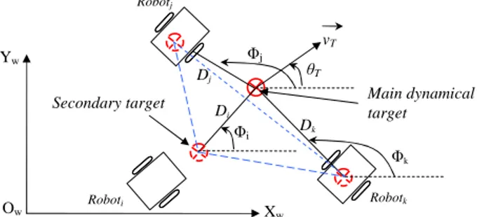
• Define one point which gives the dynamics (velocities)
of the applied structure. This point is called the main dynamical target (cf. Figure 1),
• Define the virtual structure to follow by defining as
much nodes (virtual target) as necessary to obtain the desired geometry. Each node i is called a secondary
target and is defined according to a specific distance
Di and angle Φi with respect to the main target.
Secondary targets defined by this way have then the same orientationθT and velocityvT.
An exemple to get a triangular formation is given in figure 1. Di Roboti Dj Φj Robotj θT Ow Xw Yw Main dynamical target Secondary target vT Robotk Dk Φk Φi
Fig. 1. Keeping a triangular formation by defining a virtual geometrical
structure.
B. Cooperative and Distributed virtual target assignment As discussed above, each mobile robot should follow one of the secondary targets forming the wished geometric shape, but the asked question is what targetj for what roboti? The
only information available at the level of each roboti are its
configuration (xi,yi,θi), the one of the main target (xT,yT, θT) as well as theDj andΦj corresponding to the relative
positions and orientations of the secondary targetsj with
regards to the main one (cf. Figure 1). It is also noted that to simplify the negotiation protocol between the robots [20], a specific priorities (like a hierarchy)p = 1..N is attributed for
each robot. From these information, robots will cooperate to establish with a fully distributed manner the virtual target to follow. The proposed algorithm embedded in each robot is given below:
Input: Distances dSj separating the robot with regards to the
secondary targetsj (cf. Figure 3)
Output: Choice of the virtual target to follow While (experimentation)
• classify by growing order the distances dSj separating
the robot and the targetj,
• go toward the closest target but with the condition that
it is not already chosen by one robot of superior hierarchy
p (this, stipulates that each robot communicates with other
robots its sorted list and its p rank in the hierarchy).
EndWhile
Algorithm 1: Distributed virtual target assignment
III. THEPROPOSEDCONTROLARCHITECTURE:
As cited above, the proposed control architecture includes two controllers: Attraction to a Dynamical Target and Ob-stacle Avoidance controllers (cf. Figure 2). Before giving all details about this architecture, let’s present the proposed Attraction to a Dynamical Target block and the Obstacle Avoidance block.. Attraction to Dynamical Target Roboti (PSoa, θSoa) Hierarchical set-point selection (PSi , θSi ) Control Law (vi, wi) P e rc e pt ions a nd C om m uni ca ti on inf or m a ti on Obstacle Avoidance
Parameters of the formation to achieve
(PSat, θSat)
Fig. 2. The proposed architecture of control.
A. Attraction to a Dynamical Target Controller
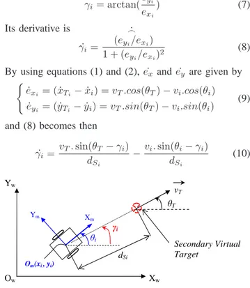
Consider a robot i with (xi, yi, θi) pose. This robot has
to track its secondary dynamical target Ti(xTi, yTi, θTi)
(cf. Section II-B)that the variation of its position can be described by
(
˙xTi = vT.cos(θT) ˙yTi= vT.sin(θT)
(1) Let’s also introduce the used robot model. Experimental results are made on Khepera III, which are unicycle mobile robots. Their kinematic model can be described by the well-known equations (cf. Equation 2).
˙xi= vi.cos(θi) ˙yi= vi.sin(θi) ˙ θi= ωi (2)
whereθi, vi andωi are respectively the robot orientation,
linear and angular velocities.
Figure (3) allows to define position errors as
(
exi = (xTi−xi) = dSicos(γi) eyi = (yTi−yi) = dSisin(γi)
(3) The current distance between the roboti and its target Ti,
noted dSi can then be expressed as
dSi = q e2 xi+ e 2 yi (4) Its derivative is ˙ dSi = exi˙exi+ eyi˙eyi dSi (5) Using equations (1 to 5) allows us to get
˙
dS i = vT. cos(γi−θT) − vi. cos(γi−θi) (6)
Similarly, the current angle of the robot according to its dynamical target is notedγi and is calculated as
γi= arctan(ey i exi ) (7) Its derivative is ˙ γi= ˙ _ (eyi/exi) 1 + (eyi/exi) 2 (8)
By using equations (1) and (2),e˙xande˙y are given by (
˙exi = ( ˙xTi− ˙xi) = vT.cos(θT) − vi.cos(θi) ˙eyi = ( ˙yTi− ˙yi) = vT.sin(θT) − vi.sin(θi)
(9) and (8) becomes then
˙ γi= vT. sin(θT −γi) dSi −vi. sin(θi−γi) dSi (10) γi Ym X m Om(xi , yi) dSi Ow Xw Yw θi θT vT Secondary Virtual Target (x , y )
Fig. 3. Attraction to a dynamical target.
To obtain the set-point angle θSat applied to the robot
in order to reach its dynamical target, our idea is to keep
γi constant. In other words, we would like to haveγ˙i= 0.
Under this constraint, we show that the defined set-point angle leads the robot on its target. Equation (10) allows thus to write: vT. sin(θT −γi) dSi −vi. sin(θi−γi) dSi = 0 (11)
The set-point angle that the robot must follow to satisfy the constraint expressed by equation (11) and to reach its dynamical target is then given by
θSat= arcsin(
vT
vi sin(θT−γi)) + γi (12)
In what follows, it is put b = vT
vi. As already cited, a
close result was given in [19]. However, the two results are differently developed. In fact, in [19], the line of sight of an observer was used to build this set-point and the position of this observer affects the set-point. The proposed work is not based on any observer and our results depend only on the dynamics of the robot and its target. Also, and unlike [19], the robot velocity in not constant. The proposed control law (cf. Section IV) regulates it by accelerating or decelerating according to the robot distancedSi with respect to its target.
The target is then tracked once reached whereas in [19], the goal was just to prove that the robot and its target meet each other.
To prove that the robot reaches its target, we have to prove thatdSi is continually decreasing. For that, it is sufficient to
prove that ˙dSi < 0. Before giving the proof, it is reported that
the linear velocity of the robot will be elaborated satisfying the constraintvi≥vT. It is natural that the robot goes faster
than to the target to reach it, especially when the latter is escaping. Therefore, we have alwaysb = vT
vi ≤1. Moreover,
the trajectory of the target is assumed smooth. For the proof, the following two properties are reminded
cos(−x) = cos(x), ∀x ∈ R
arcsin(x) ∈ [−π
2, π
2], ∀x ∈ [−1, 1]
Consider the equation (6), two cases are then possible 1) (θT −γi) ∈ [−π2 ,
π
2] (escaping target); we have:
cos(θT −γi) =p1 − (sin(θT −γi))2≥0 which leads to ˙ dSi = vTp1 − (sin(θT −γi)) 2 −vip1 − (b sin((θT −γi))2 (13)
However, while the robot did not reach the target, we
have b < 1 since vT < vi (cf. Section IV). It means
that vTp1 − (sin(θT−γi))2< vip1 − (b sin(θT −γi))2 thus ˙ dSi< 0 2) (θT −γi) ∈ [π2,3π2] (approaching target): cos(θT −γi) = −p1 − (sin(θT−γi))2≤0 and ˙ dSi = −vTp1 − (sin(θT−γi))2 −vip1 − (b sin((θT −γi))2 (14)
It can then immediately be deduced that ˙dSi< 0.
Note that in the first case (escaping target), it can be observed that ˙d is as much more negative as the linear robot
velocity is increasing. It will be seen later that the proposed control law increases the robot velocity as the distance robot-target increases. In addition, the control law is elaborated
such that the robot velocity vi → vT when dSi → 0 (cf.
Section IV). Hence, in equation (12) we have b = 1. It is
interesting to note that the proposed set-point allows thereby to converge toθT as dSi →0. In fact, Two cases are again
possible 1) (θT −γi) ∈ [−π2 ,π2] (escaping target): θSat = arcsin(sin(θT −γi)) + γi θSat = θT −γi+ γi θSat = θT (15)
The set-point angle tends directly to the target direc-tion.
2) (θT −γi) ∈ [π2,3π2] (approaching target):
θSat = π − (θT −γi) + γi
θSat = π + 2γi−θT
(16) However, the robot still reaches the target but with this set angle, it goes past it once reached. The robot is then behind the target and tries to join it again. Therefore,γi is
recalculated. Since the target trajectory is assumed smooth, the new calculated γi verifies then the case 1 (the robot is
now behind the target, and this one becomes then an escaping target).
B. Obstacle Avoidance Controller
To perform the obstacle avoidance controller, the robot needs to follow accurately limit-cycle vector fields [15], [16]. Each obstacle is surrounded with an influence circle of radius
RI = RO+Rr+∆, with ROthe real obstacle radius,Rrthe
robot radius and∆ a safety margin. Vector fields are given
by two differential equations:
• For the clockwise trajectory motion (cf. Figure 4(a)): ˙xs = ys+ xs(Rc2−x2s−y2s)
˙ys = −xs+ ys(Rc2−x2s−ys2)
(17)
• For the counter-clockwise trajectory motion (cf. Figure
4(b)):
˙xs = −ys+ xs(Rc2−x2s−ys2) ˙ys = xs+ ys(Rc2−x2s−y2s)
(18) where (xs, ys) corresponds to the position of the robot
ac-cording to the center of the convergence circle (characterized by anRcradius). Figure 4 shows that the circle of “Rc= 1”
is a periodic orbit. This periodic orbit is called a limit-cycle. Figure 4(a) and 4(b) show the shape of equations (17) and (18) respectively. They show the direction of trajectories (clockwise or counter-clockwise) according to (xs,ys) axis.
The trajectories from all points (xs,ys) including inside the
circle, move towards the circle.
The set-point angleθSoa calculated thanks to the Obstacle
Avoidance controller is given by the differential equation of the limit-cycle (17) or (18) as:
θSoa= arctan(
˙ys ˙xs)
(19) However, note that obstacle avoidance controller itself is divided into two phases: attractive phase and repulsive phase. These two cases guarantee that the robot do not navigate very
closely to RI. This causes oscillations of the robot due to
useless switch between obstacle avoidance and attraction to target controllers (see [16] for more details).
Algorithm 2 and Figure 5 explain briefly the two phases principle.(xO, yO) (cf. Algorithm 2) are the relative position
of the robot in the obstacle frame (O, XO, YO) (cf. Figure
5). This frame is built such that direction of the X-axis goes through the virtual target to reach and the obstacle center. Y-axis can then be easily deduced.
Input: All the features of the closest obstacle Output: Radius of the limit-cycle trajectory to follow if yO≥ 0then
Avoid the obstacle in the clockwise direction
else
Avoid the obstacle in the counter-clockwise direction
end
if xO≤ 0 then
Rc= RI−ξ (Attractive phase)
{with ξ a small constant value as ξ ∆ }
else
{Escape criterion: go out of the obstacle circle of influence with a smooth way}
Rc = Rc + ξ (Repulsive phase)
end
Algorithm 2: Obtaining the radiusRc of the limit-cycle.
C. The remaining control architecture blocks
The proposed control architecture is summarized in Figure 2. First, the parameters of the rigid virtual structure
(Di, Φi) (cf. Section II) are given by the Parameters of
the formation to achieve block. Besides, according to the task accomplished by the robot, the corresponding controller is chosen thanks to the Hierarchical Set-Point Selection block. The latter takes a decision thanks to environment information collected by the Perceptions and Communication block and the robot (block) which gives its current position. The corresponding set-points(PSi, θSi) are then sent to the
Control Law block according to the active controller such that
• (PSi = (xSi, ySi)) is the current position of the
dy-namical target (PSat = (xTi, yTi)) and (θSi = θSat)
for Attraction to Dynamical Target controller,
• PSoa is always set to (0, 0) and (θSi = θSoa) for
Obstacle Avoidance controller.
It is important to emphasize that the control block uses the same control law for both controllers. Therefore, only the set-points change coming from a controller or an other. In next section, the proposed control law is given in details.
-3 -2 -1 0 1 2 3 -3 -2 -1 0 1 2 3 xs ys (a) Clockwise -3 -2 -1 0 1 2 3 -3 -2 -1 0 1 2 3 x s ys (b) Counter-Clockwise
Obstaclei Secondary Virtual Target Robot O Y XO A X A Y A O (1) Clockwise Attraction (3) Conter-Clockwise Repulsion (4) Clockwise Repulsion (2) Conter-Clockwise Attraction RI
Fig. 5. The 4 specific areas surrounding the obstacle to avoid
IV. THE PROPOSED CONTROL LAW
The proposed control law allows to each robot i to
converge to its set-point (cf. Figure 2). It is expressed as
vi= vmax−(vmax−vT)e−(d
2
Si/σ2) (20a)
ωi = ωSi+ k1θ˜i (20b)
where
• vmax is the maximum linear speed of the robot, • σ, k1 are positive constants,
• vi andωiare as already defined (cf. Section III) linear
and angular velocities of the robot.wSi= ˙θSi. ˜
θi= θSi−θi (21)
where θSi is the set-point angle according to the active
controller (cf. Section III) and was already computed (cf. Equation (12), (19)).
By derivating
˙˜θi= wSi−ωi (22)
Consider the Lyapunov function V=1
2θ˜i 2
(23) The control law is asymptotically stable if ˙V < 0.
˙
V = k1θ˜i˙˜θi
By replacing equation (22) in the control law (20b), we
get ˙˜θ
i= −k1θ˜i
and ˙V becomes V = −k˙
1θ˜2i < 0
for every ˜θi6= 0 since k1> 0.
V. EXPERIMENTALRESULTS
Experimentations are implemented on Khepera III robots. Navigation is achieved on a platform equipped with a camera giving positions and orientation of the robots and the obsta-cles to avoid. In fact, every element (robot, obstacle) has a different bar code to identify it at each moment: (position, orientation, radius, etc.) [21].
A. Extension of the navigating formation shape
To test the relevance of the proposed control architecture to reach and to maintain a formation shape, a triangular virtual structure is defined. It moves with a constant linear speed
vT = 4.2cm/s. Three Khepera III are randomly put on the
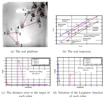
platform. The proposed architecture of control is embedded on each robot. Results are given in figure (6). It can be seen that each one joins the closest virtual target of the virtual structure (cf. Figure 6(a)). The real trajectory of the three robots is given in figure 6(b). While navigation, it is proposed to extend the virtual structure to a diamond shape. Therefore, an other robot is added to the formation. It can be seen that the robot accelerates, and reaches the free virtual target without disturbing the other navigating robots. The distance errors between the robot and their targets are given in figure 6(c). It can be seen that the all the robots reaches their targets (the distance error tends to 0). The evolution of the Lyapunov function of each robot is given in figure 6(d). It can be seen that it is decreasing despite some variations (noise) due to the error localization given by the camera. The definition of the Lyapunov function (cf. Equation 23) allows to deduce that the angular error ˜θ tends also to 0.
ti ti+1 ti+2 1 2 3 4 2 2 1 4 3 1 3
(a) The real platform
0 0.5 1 1.5 0.2 0.4 0.6 0.8 1 1.2 1.4 1.6 1.8 [m] [m ] Initial position of robot 4 Initial position of robot 2 Initial position of robot 1 Initial position of robot 3 ti ti+1 ti+2
Virtual triangular formation set-point at moment t Formation becoming a diamond ti X(m) Y (m )
(b) The real trajectory
0 10 20 30 40 50 60 70 80 0 0.05 0.1 0.15 0.2 0.25 0.3 0.35 0.4 0.45 0.5 Time[s/10] d [ m ] Robot 1 Robot 2 Robot 3 Robot 4 (the added one)
Moment of adding the robot 4
(c) The distance error to the target of each robot 0 10 20 30 40 50 60 70 80 0 0.2 0.4 0.6 0.8 1 1.2 1.4 1.6 Time[s/10] V [ rd ²] Robot 1 Robot 2 Robot 3 Robot 4 (the added one)
Moment of adding the robot 4
(d) Variation of the Lyapunov function of each robot
Fig. 6. Extension of the triangular formation to a diamond formation shape.
B. Joining the formation while avoiding obstacles
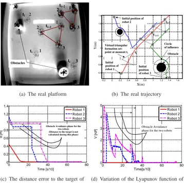
A triangular virtual shape is desired in this experimenta-tion. Three Khepera III robots have then to reach the cor-responding closest target. However, two hindering obstacles prevents two robots from directly catching their targets. It is observed (cf. Figure 7) that the two robots avoid the obstacles, and reach the closest target (cf. Figure 7(a)). The real trajectories of the robots and obstacle positions are given in figure 7(b). Distance errors of the robot to their chosen targets are given in figure 7(c). It can be seen that each robot converges to its virtual target. In the obstacle avoidance phase (cf. Figure 7(c)) for robot 2 and 3, it is noted that the distance of the robot to its target is not taken into
account(PSi = (0, 0) (cf. Section III)). The last computed
distance is kept in robot memory but is not used. When switching into Attraction to Dynamical Target controller again, the distance error decreases until the robot reaches the target. Switch moments can be easily detected thanks to the Lyapunov function variation (cf. Figure 7(d)). In fact, an abrupt change of the set-point angle leads to a jump in the Lyapunov function. Outside the switch moment, each Lyapunov function is decreasing. Note that in the obstacle avoidance phase, two jumps are observed for each robots. The second one corresponds to switching from attraction phase to repulsive phase (cf. Section III-B) [22].
1 1 2 3 2 3 Obstacles 1 2 3 ti ti ti ti+1 ti+2
(a) The real platform
-0.2 0 0.2 0.4 0.6 0.8 1 1.2 1.4 1.6 0.4 0.6 0.8 1 1.2 1.4 1.6 1.8 Initial position of robot 1 Initial position of robot 2 Initial position of robot 3 Virtual triangular formation
set-point at moment ti Obstacle Circle of influence ti t i+1 ti+2 X(m) Y (m )
(b) The real trajectory
0 20 40 60 80 0 0.2 0.4 0.6 0.8 1 1.2 1.4 Time[s/10] d [ m ] Robot 1 Robot 2 Robot 3
Obstacle Avoidance phase for the two robots (Distance to the target is not calculated during this phase)
Time [s/10]
(c) The distance error to the target of each robot 0 20 40 60 80 0 1 2 3 4
5 Evolution of the Lyapunov function of the robots
Time[s/10] V [ rd ²] Robot 1 Robot 2 Robot 3 Obstacle Avoidance phase for the two robots
(d) Variation of the Lyapunov function of each robot
Fig. 7. Avoiding obstacles before joining the formation.
VI. CONCLUSIONS AND FUTURE WORKS The problem of multi-robot formation was studied while designing an appropriate control architecture. It allows to reach and to maintain a desired virtual shape for a group of robots during the navigation. This navigation is accom-plished in unstructured environments. Consequently, each robot has to avoid disturbing obstacles using limit-cycle method before rejoining the formation. Limit-cycle method allows to the robot to choose the optimal avoidance side to rapidly reach its target. If two tasks have to be achieved (Attraction to a Dynamical Target and Obstacle Avoidance), only one sufficient control law is used. Switching between tasks occurs by choosing the appropriate set-points. The proposed architecture offers flexibility to add other robots to the formation even during the navigation. Unlike potential field methods, this is accomplished without affecting or modifying the control laws of the other existing robots.
Stability of the overall control especially in the switch moments will be deeply exposed in a future paper. Collision between robots was not treated in this paper (dynamical obstacle avoidance), it will be subject of future works.
REFERENCES
[1] L Adouane and L.F Nadine. Hybrid behavioral control architecture for the cooperation of minimalist mobile robots. International Conference
On Robotics And Automation, pages 3735–3740, 2004.
[2] Y. Hirata, K. Kosuge, H. Asama, H. Kaetsu, and K. Kawabata. Transportation of an object by multiple distributed robot helpers in
cooperation with a human. Transactions of the Japan Society of
Mechanical Engineers, 68(668):1207–1214, 2002.
[3] B. Jouvencel, V. Creuze, and P. Baccou. A new method for multiple auv coordination: a reactive approach. 8th IEEE International
Con-ference on Emerging Technologies and Factory Automation, 1:51–55,
october 2001.
[4] R. Alami, M. Herrb, Ingrand F., and F. Robert. Multi-robot cooperation
in the martha project. IEEE Robotics and Automation Magazine,
5(1):36 – 47, 1998.
[5] J. Bom, B. Thuilot, F. Marmoiton, and P. Martinet. Nonlinear control for urban vehicles platooning, relying upon a unique kinematic gps. In
International Conference on Robotics and Automation, pages 4149–
4154, 2005.
[6] H.G. Tanner, G.J Pappas, and V. Kumar. Leader-to-formation stability.
IEEE Transactions on Robotics and Automation, 20(3):433 ˝U455, 2004.
[7] G. Antonelli, F. Arrichiello, S. Chakraborti, and S. Chiaverini. Ex-periences of formation control of mutli-robot systems with the null-space-based behavioral control. In IEEE International Conference on
Robotics and Automation, pages 1068–1073, 2007.
[8] T. Balch and R. C. Arkin. Behavior-based formation control for
multirobot systems. IEEE Transactions on Robotics and Automation,
14(12):926 ˝U939, 1998.
[9] K. D. Do. Formation tracking control of unicycle-type mobile robots. In IEEE International Conference on Robotics and Automation, pages 527–538, 2007.
[10] X. Li, J. Xiao, and Z. Cai. Backstepping based multiple mobile robots formation control. In IEEE International Conference on Intelligent
Robots and Systems, pages 887 – 892, 2005.
[11] R. Beard, J. Lawton, and F. Hadaegh. A coordination architecture for spacecraft formation control. IEEE Transactions on Control Systems
Technology, 9:777–790, 2001.
[12] P. Ögren, E. Fiorelli, and Leonard N. E. Formations with a mission: Stable coordination of vehicle group maneuvers. In 15th International
Symposium on Mathematical Theory of Networks and Systems, 2002.
[13] S. Mastellone, D.M. Stipanovic, and M.W. Spong. Remote formation control and collision avoidance for multi-agent nonholonomic systems. In IEEE International Conference on Robotics and Automation, pages 1062–1067, 2007.
[14] O. Khatib. Real time obstacle avoidance for manipulators and mobile robots. International Journal of Robotics Research, 5:90–99, 1986. [15] D. Kim and J. Kim. A real-time limit-cycle navigation method for
fast mobile robots and its application to robot soccer. Robotics and
Autonomous Systems, 42:17–30, 2003.
[16] L. Adouane. Orbital obstacle avoidance algorithm for reliable and on-line mobile robot navigation. In 9th Conference on Autonomous
Robot Systems and Competitions, May 2009.
[17] N. Tatematsu and K. Ohnishi. Tracking motion of mobile robot for moving target using nurbs curve. In IEEE International Conference
on Industrial Technology, volume 1, pages 245 – 249, 2003.
[18] Q. Chen and Luh J. Y. S. Coordination and control of a group of small mobile robots. In IEEE International Conference on Robotics
and Automation, pages 2315–2320, 1994.
[19] F. Belkhouche, B. Belkhouche, and P. Rastgoufard. Line of sight robot navigation toward a moving goal. IEEE Transactions on Systems, Man,
and Cybernetics, Part B, 36(2):255–267, 2006.
[20] P. Gerkey Brian and J Mataric Maja. Sold!: Auction methods for multi-robot coordination. IEEE Transactions on Robotics and Automation,
Special Issue on Multi-robot Systems, 18(5):758–768, 2002.
[21] P. Lébraly, C. Deymier, O. Ait-Aider, E. Royer, and M. Dhome. Flexible extrinsic calibration of non-overlapping cameras using a pla-nar mirror: Application to vision-based robotics. IEEE International
Conference on Intelligent Robots and Systems, page to appear, 2010.
[22] L. Adouane. Hybrid and safe control architecture for mobile robot
navigation. In 9th Conference on Autonomous Robot Systems and