UNIVERSITÉ DE MONTRÉAL
PRACTICAL MICROSTRUCTURED AND PLASMONIC
TERAHERTZ WAVEGUIDES
ANDREY MARKOV
DÉPARTEMENT DE GÉNIE PHYSIQUE ÉCOLE POLYTECHNIQUE DE MONTRÉAL
THÈSE PRÉSENTÉE EN VUE DE L’OBTENTION DU DIPLÔME DE PHILOSOPHIAE DOCTOR
(GÉNIE PHYSIQUE) MAI 2015
UNIVERSITÉ DE MONTRÉAL
ÉCOLE POLYTECHNIQUE DE MONTRÉAL
Cette thèse intitulée:
PRACTICAL MICROSTRUCTURED AND PLASMONIC
TERAHERTZ WAVEGUIDES
présentée par : MARKOV Andrey
en vue de l’obtention du diplôme de : Philosophiae Doctor a été dûment acceptée par le jury d’examen constitué de : M. FRANCOEUR Sébastien, Ph. D., président
M. SKOROBOGATIY Maksim A., Ph. D, membre et directeur de recherche M. MEUNIER Michel, Ph. D, membre
ACKNOWLEDGEMENTS
I would like to express my heartfelt gratitude to my supervisor and research director Prof. Maksim Skorobogatiy for his guidance during my PhD study, his invaluable assistance and support. Maksim’s help allowed me to pursue successfully my scientific dream, become more mature, and enrich my curiosity.
I have been surrounded by wonderful colleagues Bora Ung, Stephan Gorgutsa, Anna Mazhorova, Mathieu Rozé, Hang Qu, Hichem Guerboukha and others. I would like to thank them for the helpful discussions, productive mutual work, and simply support during the five years of my studies.
Finally I would like to give a special acknowledgement to my parents and my fiancé, Stephanie. They have always been understanding and patient, and I could always address to them for the encouragement and support when I needed it.
RÉSUMÉ
La bande térahertz, comprenant les fréquences entre 100 GHz et 10 THz, présente un fort potentiel pour diverses applications technologiques et scientifiques, telles que la détection, l’imagerie, le secteur des communications ainsi que la spectroscopie. La plupart des sources térahertz (THz) sont immobiles et, dans les systèmes THz existants, la propagation de l’onde se fait dans l’air libre, afin de minimiser les pertes de transmission. Le design efficace de guides d’onde THz est important pour des applications pratiques des techniques THz. Ces guides d’onde permettraient une meilleure intégration de plusieurs composants en un système THz unique: les sources, les détecteurs, les filtres etc.
L'application la plus évidente des guides d'onde THz est la livraison de l'onde de la source au détecteur. Les composants optiques encombrants pourraient être remplacés et le tout pourrait être incorporé dans un système compact de spectroscopie THz dans le domaine temporel. L'imagerie et la détection sont d'autres avenues prometteuses pour les guides d'onde THz. Il a déjà été démontré que les guides d'ondes THz peuvent opérer en régime sub-longueur d'onde, offrant ainsi un confinement du mode guidé plus petit que la limite de diffraction. Ainsi, la résolution spatiale de ces guides d'onde surpassent celle des systèmes THz conventionnels.
Pour un design efficace des guides d'onde THz, il est important de minimiser les pertes et la dispersion. Une solution potentielle serait d'augmenter la fraction de la puissance modale qui se propage dans l'air. Dans cette thèse, nous abordons l'utilisation de guides d'onde air/diélectrique, planaires et poreux, ainsi que de guides d'onde hybrides fils métalliques/diélectriques.
D'abord, nous présentons un nouveau design de guide d'onde planaire et poreux. Nous décrivons sa fabrication et nous le caractérisons pour une potentielle application comme guide d'onde et comme senseur dans le spectre THz. Le guide d'onde est formé de plusieurs minces films de polyéthylène (25 - 50 µm) séparés par des couches d'air d'épaisseurs comparables. Une grande portion du champ électrique est guidée dans l'air, permettant ainsi de réduire significativement les pertes par transmission. Également, nous constatons qu'un tel guide d'onde peut s'avérer utile pour des applications de détection biologique et chimique, en plaçant directement les échantillons dans la microstructure. Le guide d'onde planaire proposé possède l'avantage principal de permettre l'accès aisé au mode optique, puisque la majorité de la puissance THz introduite est confiné dans les couches d'air. De plus, le petit espacement entre les couches permet l'introduction rapide
d'analytes par effet capillaire (moins d'une seconde est nécessaire pour remplir un guide d'onde de 10 cm de long). La transmission et l'absorption du guide d'onde a été étudié expérimentalement, avec un système de spectroscopie THz dans le domaine temporel, et théoriquement, avec un logiciel de calcul par éléments finis. L'indice de réfraction modal du guide d'onde poreux est inférieur au guide d'onde plein. Il est possible par ailleurs d'ajuster cet indice en modifiant l'espacement entre les couches, ainsi que le nombre de couches dans le cœur. Également, les pertes de transmission dans le guide d'onde poreux sont considérablement inférieures aux pertes dans le guide d'onde plein.
Dans les chapitres subséquents, nous examinons une autre approche prometteuse pour le design de guides d'onde THz à faibles pertes et peu dispersifs. Le guide d'onde hybride métallique/diélectrique permet la propagation d'un mode plasmonique guidé dans le gap entre deux fils métalliques parallèles. Le tout est encapsulé dans une gaine micro-structurée diélectrique qui permet de donner une stabilité mécanique et d'isoler le guide d'onde de l'environnement. Nous décrivons plusieurs techniques prometteuses d'encapsulation du guide d'onde à deux fils, tout en minimisant l'impact négatif sur la propagation dû à l'ajout de la gaine diélectrique. En particulier, nous détaillons l'utilisation de mousses à faible densité et de plastiques micro-structurés.
Les guides d'ondes hybrides s'avèrent plus commodes pour les applications pratiques que les guides d'onde classiques à deux fils, puisqu'ils permettent la manipulation de la fibre sans risquer de perturber le mode guidé. Nous présentons une analyse détaillée des propriétés de propagation modale du guide d'onde hybride métallique/diélectrique et nous les comparons avec celles d'un guide d'onde à deux fils classique. Aussi, nous discutons des stratégies pour améliorer la performance des guides d'onde, notamment l'utilisation de gaines micro-structurées plus poreuses ou de matériaux intrinsèquement poreux. Nous étudions l'efficacité de couplage de l'onde vers le guide d'onde hybride et nous constatons qu'il peut être relativement élevé (>50%) aux fréquences aux alentours de ~0.5 THz.
Sans surprise, les performances de ces guides d'onde sont inférieures à celles des guides d'onde classiques à deux fils, en raison de la présence du diélectrique près du gap entre les deux fils. Parallèlement, l'ajout des fils métalliques permet de surpasser les guides d'onde poreux sans fils, en termes de largeur de bande passante et de dispersion. Nous démontrons que les guides d'onde hybrides métalliques/diélectrique poreux peuvent avoir des largeurs de bande passante très
grandes, car les modes sont confinés dans l'air aux hautes et bases fréquences. Aux hautes fréquences, ceci est dû au mécanisme de propagation ARROW, alors qu'aux basses fréquences, le mécanisme est plutôt de propagation plasmonique, dans le gap entre les deux fils.
Finalement, nous décrivons une propriété de résonance intéressante de certains modes plasmoniques hybrides métalliques/diélectriques. Cette résonance se manifeste lors du passage du confinement dans le diélectrique au confinement dans l'air. Nous discutons de la possibilité d'utiliser cette propriété pour construire des réfractomètres THz. L'introduction d'analytes à très faibles pertes permet tout de même des changements significatifs dans les pertes modales. Ces pertes sont utilisées comme mécanisme de transduction. La résolution du refractomètre a été étudiée numériquement en fonction de la fréquence d'opération et des paramètres géométriques de la fibre. Avec une résolution de l'indice de réfraction de l'ordre de ~10-3, le senseur permet
l'identification de plusieurs aérosols et analytes gazeux, ainsi que de mesurer la concentration de particules de poussières dans l'air.
ABSTRACT
The terahertz frequency range, with frequencies lying between 100 GHz and 10 THz, has strong potential for various technological and scientific applications such as sensing, imaging, communications, and spectroscopy. Most terahertz (THz) sources are immobile and THz systems use free-space propagation in dry air where losses are minimal. Designing efficient THz waveguides for flexible delivery of broadband THz radiation is an important step towards practical applications of terahertz techniques. THz waveguides can be very useful on the system integration level when used for connection of the diverse THz point devices, such as sources, filters, sensor cells, detectors, etc.
The most straightforward application of waveguides is to deliver electromagnetic waves from the source to the point of detection. Cumbersome free-space optics can be replaced by waveguides operating in the THz range, which could lead to the development of compact THz time domain spectroscopy systems. Other promising applications of THz waveguides are in sensing and imaging. THz waveguides have also been shown to operate in subwavelength regimes, offering mode confinement in waveguide structures with a size smaller than the diffraction limit, and thus, surpassing the resolution of free-space THz imaging systems.
In order to design efficient terahertz waveguides, the frequency dependent loss and dispersion of the waveguide must be minimized. A possible solution would be to increase the fraction of mode power propagating through air. In this thesis, the usage of planar porous air/dielectric waveguides and metal wire/dielectric hybrid terahertz fibers will be discussed.
First, I present a novel design of a planar porous low-loss waveguide, describe its fabrication, and characterize it in view of its potential applications as a low-loss waveguide and sensor in the THz spectral range. The waveguide structure features a periodic sequence of layers of thin (25-50 µm) polyethylene film that are separated by low-loss air layers of comparable thickness. A large fraction of the modal fields in these waveguides is guided in the low-loss air region, thus effectively reducing the waveguide transmission losses. I consider that such waveguides can be useful not only for low-loss THz wave delivery, but also for sensing of biological and chemical specimens in the terahertz region, by placing the recognition elements directly into the waveguide microstructure. The main advantage of the proposed planar porous waveguide is the convenient access to its optical mode, since the major portion of THz power
launched into such a waveguide is confined within the air layers. Moreover, small spacing between the layers promotes rapid loading of the analyte into the waveguide due to strong capillary effect (< 1 s filling of a 10 cm long waveguide with an analyte). The transmission and absorption properties of such waveguides have been investigated both experimentally using THz-TDS spectroscopy and theoretically using finite element software. The modal refractive index of porous waveguides is smaller compared to pure polymer and it is easy to adjust by changing the air spacing between the layers, as well as the number of layers in the core. The porous waveguide exhibits considerably smaller transmission losses than bulk material.
In the following chapters I review another promising approach towards designing of low-loss, low-dispersion THz waveguides. The hybrid metal/dielectric waveguides use a plasmonic mode guided in the gap between two parallel wires that are, in turn, encapsulated inside a low-loss, low-refractive index, micro-structured cladding that provides mechanical stability and isolation from the environment. I describe several promising techniques that can be used to encapsulate the two-wire waveguides, while minimizing the negative impact of dielectric cladding on the waveguide optical properties. In particular, I detail the use of low-density foams and microstructured plastic claddings as two enabling materials for the two-wire waveguide encapsulation.
The hybrid fiber design is more convenient for practical applications than a classic two metal wire THz waveguide as it allows direct manipulations of the fiber without the risk of perturbing its core-guided mode. I present a detailed analysis of the modal properties of the hybrid metal/dielectric waveguides, compare them with the properties of a classic two-wire waveguide, and then present strategies for the improvement of hybrid waveguide performance by using higher cladding porosity or utilizing inherently porous cladding material. I study coupling efficiency into hybrid waveguides and conclude that it can be relatively high (>50%) in the broad frequency range ~0.5 THz.
Not surprisingly, optical properties of such fibers are inferior to those of a classic two-wire waveguide due to the presence of lossy dielectric near an inter-wire gap. At the same time, composite fibers outperform porous fibers of the same geometry both in bandwidth of operation and in lower dispersion. I demonstrate that hybrid metal/dielectric porous waveguides can have a very large operational bandwidth, while supporting tightly confined, air-bound modes both at high
and low frequencies. This is possible as, at higher frequencies, hybrid fibers can support ARROW-like low-loss air-bound modes, while changing their guidance mechanism to plasmonic confinement in the inter-wire air gap at lower frequencies.
Finally, I describe an intriguing resonant property of some hybrid plasmonic modes of metal / dielectric waveguides that manifests itself in the strong frequency dependent change in the modal confinement from dielectric-bound to air-bound. I discuss how this property can be used to construct THz refractometers. Introduction of even lossless analytes into the fiber core leads to significant changes in the modal losses, which is used as a transduction mechanism. The resolution of the refractometer has been investigated numerically as a function of the operation frequency and the geometric parameters of the fiber. With a refractive index resolution on the order of ∼10−3 RIU, the composite fiber-based sensor is capable of identifying various gaseous analytes and aerosols or measuring the concentration of dust particles in the air.
TABLE OF CONTENTS
ACKNOWLEDGEMENTS ... III RÉSUMÉ ... IV ABSTRACT ...VII TABLE OF CONTENTS ... X LIST OF FIGURES ... XIV LIST OF SYMBOLS AND ABBREVIATIONS... XXII LIST OF APPENDICES ... XXIII
INTRODUCTION ... 1
Structure of the thesis ... 3
CHAPTER 1 LITERATURE REVIEW ... 5
1.1 Terahertz waveguides ... 5
1.1.1 Dielectric multilayered waveguides ... 6
1.1.2 Single wire waveguides ... 7
1.1.3 Two-wire waveguides ... 9
1.1.4 Composite metal-dielectric air-core fibers ... 11
1.1.5 Terahertz waveguides examples ... 14
1.2 Terahertz waveguides simulation ... 16
1.3 Applications of foams in terahertz photonics ... 18
1.4 Terahertz refractometers ... 19
1.5 Novelty of the proposed waveguides ... 20
CHAPTER 2 METHODOLOGY ... 23
2.2 Experimental setup ... 25
2.3 Fiber fabrication ... 28
CHAPTER 3 ARTICLE 1: PLANAR POROUS THZ WAVEGUIDES FOR LOW-LOSS GUIDANCE AND SENSING APPLICATIONS ... 29
3.1 Introduction ... 29
3.2 Waveguide design ... 30
3.3 Fundamental mode of the waveguide ... 32
3.4 Details of the numerical modelling of the modal fields ... 33
3.5 Measurement setup ... 34
3.6 Polyethylene refractive index and absorption losses ... 35
3.7 Waveguide transmission and dispersion measurements ... 37
3.8 Fitting experimental transmission data with a theoretical model ... 40
3.9 Conclusion ... 43
CHAPTER 4 ARTICLE 2: TWO-WIRE TERAHERTZ FIBERS WITH POROUS DIELECTRIC SUPPORT ... 44
4.1 Introduction ... 44
4.2 Classic two-wire waveguide ... 48
4.3 Composite fiber featuring two metal wires in a three-hole porous cladding ... 51
4.4 The influence of porosity on the fiber optical properties ... 59
4.5 Composite fiber featuring two metal wires in a seven-hole porous cladding ... 62
4.6 Conclusion ... 65
CHAPTER 5 ARTICLE 3: HYBRID METAL WIRE-DIELECTRIC TERAHERTZ WAVEGUIDES: CHALLENGES AND OPPORTUNITIES [INVITED] ... 68
5.1 Introduction ... 69
5.3 Two-wire THz fibers with dielectric foam cladding ... 76
Bulk polystyrene foam ... 79
Two-wire waveguide with a polystyrene foam cladding... 81
5.4 Two-wire THz fibers with microstructured dielectric cladding ... 84
Two-wire waveguides encapsulated into porous microstructured claddings featuring subwavelength holes ... 85
Sensing applications with hybrid two-wire waveguides ... 89
Experimental characterization of hybrid fibers ... 92
Fibers with embedded Indium wires ... 95
Scaling of the hybrid fiber dimensions ... 98
5.5 Conclusion ... 100
CHAPTER 6 ARTICLE 4: HYBRID PLASMONIC TERAHERTZ FIBERS FOR SENSING APPLICATIONS ... 103
6.1 Introduction ... 103
6.2 Wave guiding in composite fibers with two metal wires in dielectric cladding ... 104
6.3 Results and discussion ... 106
6.4 Conclusion ... 106
CHAPTER 7 GENERAL DISCUSSION ... 111
Additional experimental results ... 111
Waveguides performance limitations ... 114
Fiber cross section ... 114
Coupling efficiency ... 115
Characterization of terahertz waveguides ... 117
3D printing of terahertz waveguides/preforms ... 118
Future research in the area... 121
CHAPTER 8 CONCLUSIONS ... 122
REFERENCES ... 124
LIST OF FIGURES
Figure 1.1 a) Time-domain electric field waveforms detected with the receiver 3mm above and 3mm below the waveguide. b) Spatial profile of the electric field obtained by moving the THz receiver in a plane perpendicular to the waveguide axis. c) The simulated spatial profile of the electric field propagating along the wire. d) THz waveforms measured after 4 cm (black) and 24 cm (red) of propagation distance along the wire. e) Group velocity of the propagating mode as a function of frequency. f) The electric field amplitude attenuation coefficient of the propagating mode as a function of frequency. g) Experimental setup for the excitation of THz surface wave on a metal wire using scattering configuration [52]. ... 8 Figure 1.2 a) THz pulse transmitted through a 9.5 cm length of commercially available TV twin-lead antenna cable, with THz emitter and receiver at 90° to one another (solid curve); for comparison in dotted curve free-space THz transmission along a direct line-of-sight between the transmitter and receiver separated by the same 9.5 cm spacing, with no waveguide or optics in between. b) Amplitude spectra for the two THz waveforms. Adapted from [30]. .. 10 Figure 1.3 a) Cross section of a hollow core Zeonex fiber featuring two indium wires. Core
diameter is ~2 mm. The indium wires are located at the left- and right-hand side of the hollow core and are seen silver; b) Field distribution (theory) in the HE11-like mode at 1.2 THz.
Adapted from [61]. ... 12 Figure 1.4 a) Loss coefficients as measured (grey) and as simulated (red line) for a two-wire fiber.
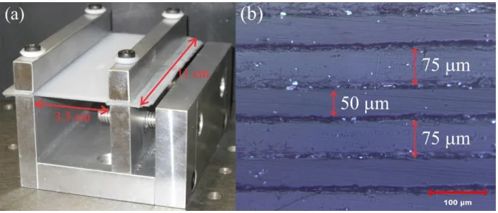
b) Normalized transmission spectrum of 8 cm two-wire fiber with different wire plane orientation with respect to the electric field polarization as indicated. The indium wires are depicted as grey ellipses while the air region is the filled white space. c) Phase refractive indices as measured (grey) and as simulated (red line) for a two-wire fiber. d) The group velocity dispersion parameter determined from the measured data (grey) and as calculated from the simulation (red line) for a two-wire and fiber. Adapted from [61]. ... 13 Figure 2.1. Experimental setup with the fiber mounted in the apertures. ... 26 Figure 3.1 (a) Photograph of the planar porous multilayer waveguide fabricated from polyethylene
the PE layers are separated by the spacers), the thickness of the polyethylene layers is 50 µm, while the thickness of spacers is 75 µm. ... 31 Figure 3.2 Transverse electric field distribution of the fundamental mode of the porous
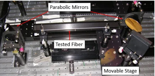
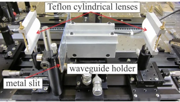
waveguide. ... 33 Figure 3.3 Experimental THz-TDS setup with the waveguide fixed between two cylindrical Teflon
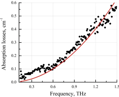
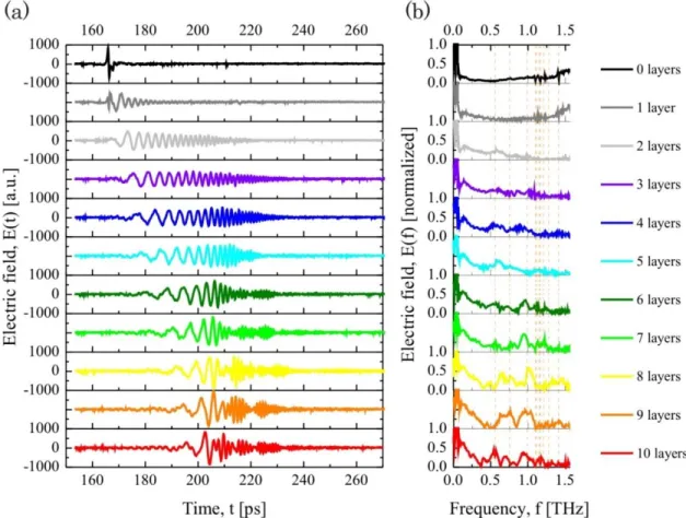
lenses. ... 35 Figure 3.4 Absorption losses of the bulk polyethylene. Red line – quadratic fitting curve. ... 36 Figure 3.5 Experimentally measured electric field (a) in time domain and (b) in frequency domain
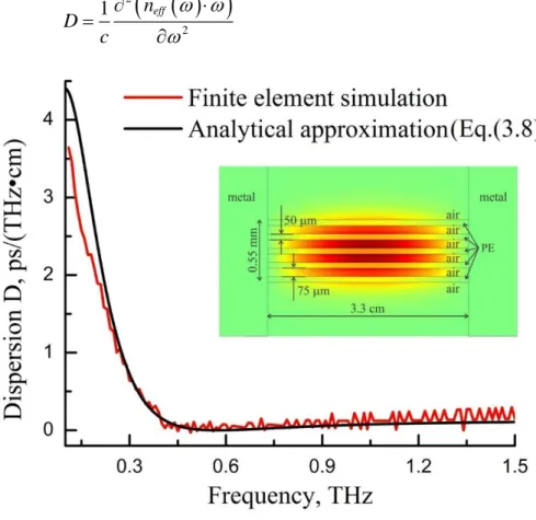
at the output of the waveguide for different number of layers in the waveguide core. Black line corresponds to the absence of the waveguide. ... 37 Figure 3.6 Dispersion of the fundamental mode of a porous waveguide; comparison between exact
simulation and analytical approximation. Black line – analytically calculated dispersion (see Equation 3.8, red line – dispersion computed using finite element method. Layer width 50 μm, spacer width 75 μm, overall waveguide size 0.55 mm, 5 PE layers. ... 39 Figure 3.7 Transverse electric field distributions of the lower order modes of the waveguide. The
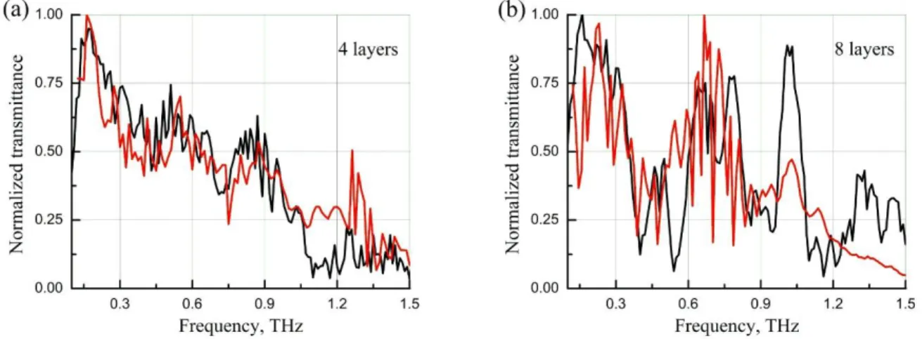
modes in the second and third columns are defined as the side modes of the fundamental (top left) and higher order modes (other modes of the first column) in the text of the chapter. ... 41 Figure 3.8 Black line – normalized experimental transmittance, red line – theoretical
normalized transmittance (a) 4 layers waveguide, 11 cm length, (b) 8 layers waveguide, 11 cm length ... 42 Figure 4.1 a) Schematic of a classic two-wire waveguide. b) Longitudinal flux distribution for the
TEM mode of a two-wire waveguide. Arrows show vectorial distribution of the corresponding transverse electric field. ... 46 Figure 4.2 a) Effective refractive index, b) absorption losses and c) group velocity dispersion of
the fundamental mode of a two metal wire waveguide shown in Figure 4.1. ... 46 Figure 4.3 Excitation efficiency of the fundamental mode of a classic two-wire waveguide using
Gaussian beam with a frequency-dependent beam diameter . as an excitation source. Dependence of the excitation efficiency on various geometrical parameters, such as: a)
displacement along the x axis from the core center; b) displacement along the y axis from the core center; c) inter-wire gap size; d) wire radius ... 50 Figure 4.4 a) Schematic of a composite fiber featuring two metal wires in a three-hole cladding.
b) Longitudinal flux distribution of a typical guided mode presents a mixture of the plasmonic mode guided by the metal wires and a TIR mode guided by the porous fiber cladding. ... 51 Figure 4.5 . Black color: the effective refractive indices, absorption losses and excitation
efficiencies for the various modes of a composite two-wire fiber shown in Figure 4.4. Red color: various optical properties of the modes of a corresponding porous cladding (no metal wires). ... 52 Figure 4.6 a) Effective refractive indices, b) excitation efficiencies, c) absorption losses and
d) group velocity dispersion for the various modes of a composite two-wire fiber shown in Figure 4.4. Dips in the excitation efficiency versus frequency graph correspond to the frequencies of anticrossing between the plasmonic modes and the fiber cladding modes. ... 53 Figure 4.7 Longitudinal flux distribution of the fundamental plasmonic mode of a composite fiber
at various operation frequencies. The flux is normalized at its maximal value at each frequency. ... 54 Figure 4.8 Longitudinal flux distribution of the lowest order cladding mode of a composite fiber at
various frequencies. The flux is normalized at its maximal value at each frequency. ... 55 Figure 4.9 Longitudinal flux distribution of the fundamental mode of a porous fiber (same cross
section as in Figure 4.4, however, without metal wires). The flux is normalized at its maximal value at each frequency. ... 56 Figure 4.10 Longitudinal flux distribution of the second plasmonic mode of a composite fiber. The
flux is normalized at its maximal value at each frequency. ... 57 Figure 4.11 a) Schematic of a seven-hole fiber with overlapping holes. b) Absorption losses,
c) excitation efficiencies, and d) effective refractive index of the various modes of the seven-hole fiber with overlapping seven-holes. ... 60 Figure 4.12 Longitudinal flux distribution for the modes of a composite seven-hole fiber with
mode, c) second plasmonic mode. The flux is normalized at its maximal value at each frequency. ... 61 Figure 4.13 a) Schematic of a seven-hole fiber with two metal wires. b) Longitudinal flux
distribution for a typical guided mode of a composite fiber presents a mixture of the plasmonic mode guided by the metal wires and a TIR mode guided by the fiber cladding. ... 62 Figure 4.14 a) Effective refractive indices, b) excitation efficiencies, c) absorption losses and
d) group velocity dispersion for the various modes of a seven-hole composite fiber shown in Figure 4.14. Solid lines define frequency ranges where the modal excitation efficiency is higher than 10%. ... 63 Figure 4.15. Longitudinal flux distribution for the modes of a seven-hole composite fiber a)
fundamental plasmonic mode, b) lowest order cladding mode, c) second plasmonic mode. The flux is normalized at its maximal value at each frequency. ... 64 Figure 5.1. a) Time-domain electric field waveforms detected with the receiver 3mm above and
3mm below the waveguide. b) Spatial profile of the electric field obtained by moving the THz receiver in a plane perpendicular to the waveguide axis. c) The simulated spatial profile of the electric field propagating along the wire. d) THz waveforms measured after 4 cm (black) and 24 cm (red) of propagation distance along the wire. e) Group velocity of the propagating mode as a function of frequency. f) The electric field amplitude attenuation coefficient of the propagating mode as a function of frequency. Adapted by permission from Macmillan Publishers Ltd © 2004. ... 71 Figure 5.2. a) Schematic of a two-wire waveguide. b) Longitudinal flux distribution for the TEM
mode of a two-wire waveguide. Arrows show vectorial distribution of the modal transverse electric field. ... 72 Figure 5.3. a) Effective refractive index, b) absorption losses, and c) group velocity dispersion of
the fundamental mode of a two metal wire waveguide shown in Figure 5.2. ... 73 Figure 5.4. Excitation efficiency of the fundamental mode of a two-wire waveguide using
diffraction limited Gaussian beam as an excitation source. Dependence of the excitation efficiency on various geometrical parameters, such as: a) displacement along the x axis from
the core center, b) displacement along the y axis from the core center, c) inter-wire gap size, and d) wire radius. ... 74 Figure 5.5. a) A two-wire THz waveguide made in our research group. b) THz waveform at the
input of the waveguide. c) THz pulse transmitted through a 10 cm-long waveguide... 75 Figure 5.6. a) THz pulse transmitted through a 9.5 cm length of commercially available TV twin-lead antenna cable, with THz emitter and receiver at 90° to one another (solid curve); for comparison in dotted curve free-space THz transmission along a direct line-of-sight between the transmitter and receiver separated by the same 9.5 cm spacing, with no waveguide or optics in between. b) Amplitude spectra for the two THz waveforms. ... 76 Figure 5.7 a) Time-domain electric field. b) Transmission spectra c) Unwrapped phase relative to
the reference. Each color represents a particular length of polystyrene foam. ... 79 Figure 5.8 a) Effective refractive index. The mean is indicated by the dashed line. b) Extinction
losses and fit with a forth order polynomial and Lorentzian function ... 81 Figure 5.9 Photograph of the two-wire ABS 3D-printed holder a) with and b) without polystyrene
foam. c) Magnification of the metal coupler used also as an aperture. d) Holder with two wires between two apertures inside the THz-TDS system. ... 82 Figure 5.10 Time domain electric field of a) the two-wire waveguide embedded in polystyrene
foam, b) the two wires only, and c) the ABS holder only. d) Transmission spectra of the corresponding electric field. ... 83 Figure 5.11. Cross sections of several hybrid fibers fabricated in our group. Microstructured
claddings of these fibers feature: a) three-interconnected holes, b) four-interconnected holes, c) web of thin bridges that is used to support metallic wires, and d) three rings of holes positioned on a hexagonal lattice. ... 84 Figure 5.12. a) Schematic of a composite three-hole fiber. b) Longitudinal flux distribution for the
fundamental plasmonic mode at 0.2 THz of a composite three-hole fiber. c) Effective refractive indices, d) excitation efficiencies, e) absorption losses, and f) group velocity dispersion for the various modes of a composite three-hole fiber. We use dotted curves at frequencies for which modal excitation efficiency drops below 5%. As an excitation source we use linearly polarized, diffraction limited Gaussian beam. ... 86
Figure 5.13. a) Schematics of a composite three-hole fiber. b) Longitudinal flux distribution for a typical guided mode of a composite seven-hole porous fiber. c) Effective refractive indices, d) excitation efficiencies, e) absorption losses, and f) group velocity dispersion for the various modes of a composite seven-hole fiber. We use dotted curves at frequencies for which modal excitation efficiency drops below 5%. As a source we assume linearly polarized, diffraction limited Gaussian beam. ... 88 Figure 5.14. Longitudinal flux distribution for the second plasmonic mode at a) 0.60THz, b) 0.80
THz. Arrows show vectorial distribution of the corresponding transverse electric field. Changes in the optical properties of the plasmonic mode as a function of the analyte refractive index. c) Modal effective refractive index, d) absorption losses. ... 89 Figure 5.15. a) Absorption losses of the plasmonic mode, and corresponding b) sensitivity of the
refractometer as a function the refractive index of the analyte at various values of the operation frequency. ... 91 Figure 5.16. Resolution of the hybrid fiber-based refractometer as a function of a) fiber diameter,
b) wire diameter, and c) gap between the wires. ... 91 Figure.5.17 a) Cross section of a hybrid 20cm-long three-hole fiber. b) Experimentally measured
transmission spectra, blue curve – wires oriented along the polarization of the input THz field, red curve – wires are perpendicular to the polarization of the input THz field, green curve – wires are removed, thus leaving behind a porous dielectric cladding, purple curve – the fiber is removed from the holders. ... 92 Figure 5.18 a) Cross section of a hybrid 10cm-long fiber with thin bridges supporting metallic
wires and b) experimentally measured transmission spectra. c) Cross section of a hybrid 10cm-long fiber with thin bridges supporting larger metallic wires and d) experimentally measured transmission spectra. e) Cross section of a hybrid 5cm-long fiber with hexagonal lattice of air holes with two metallic wires and f) experimentally measured transmission spectra. For all the transmission spectra: blue curves – wires oriented along the polarization of the input THz field, red curves – wires are perpendicular to the polarization of the input THz field, green curves – wires are removed, thus leaving behind a porous dielectric cladding. ... 94 Figure.5.19 a) Cross section of a hollow core Zeonex fiber featuring two indium wires. Core
core and are seen silver; b) Field distribution (theory) in the HE11-like mode at 1.2 THz.
Adapted from [61]. ... 95 Figure 5.20 a) Loss coefficients as measured (grey) and as simulated (red line) for a two-wire fiber.
b) Normalized transmission spectrum of 8 cm two-wire fiber with different wire plane orientation with respect to the electric field polarization as indicated. The indium wires are depicted as grey ellipses while the air region is the filled white space. c) Phase refractive indices as measured (grey) and as simulated (red line) for a two-wire fiber. d) The group velocity dispersion parameter determined from the measured data (grey) and as calculated from the simulation (red line) for a two-wire and fiber. Adapted from [61]. ... 97 Figure 5.21 a) Core-bound HE11-like modes similar to those reported in [61]. b) Plasmonic-like
modes similar to those described in chapter 4.3 and paper [123]. The number below each graph indicates the size of the air gap between the two wires. Adapted from [126]. ... 99 Figure 6.1 a) Schematic of the composite three-hole fiber. b) Longitudinal flux distribution for the
plasmonic mode in a composite fiber at 0.71 THz. Arrows show vectorial distribution of the corresponding transverse electric field. ... 104 Figure 6.2 Longitudinal flux distribution for the plasmonic mode of a composite fiber at various
frequencies. ... 105 Figure 6.3 Changes in the optical properties of a plasmonic mode as a function of the analyte
refractive index. a) Modal effective refractive index, b) absorption losses. ... 107 Figure 6.4 a) Absorption losses of the plasmonic mode, and corresponding b) Sensitivity of the
refractometer as a function the refractive index of the analyte at various values of the operation frequency. ... 108 Figure 6.5 Resolution of the refractometer as a function of a) fiber diameter, b) wire diameter, c)
gap between the wires. ... 110 Figure 7.1 a) Cross section of a hybrid 20cm-long three-hole fiber. b) Experimentally measured
transmission spectra; c) Cross section of a hybrid 10cm-long fiber with thin bridges supporting metallic wires and d) experimentally measured transmission spectra. e) Cross section of a hybrid 10cm-long fiber with thin bridges supporting larger metallic wires and f) experimentally measured transmission spectra. g) Cross section of a hybrid 5cm-long fiber
with hexagonal lattice of air holes with two metallic wires and h) experimentally measured transmission spectra. For all the transmission spectra: blue curves – wires oriented along the polarization of the input THz field, red curves – wires are perpendicular to the polarization of the input THz field, green curves – wires are removed, thus leaving behind a porous dielectric cladding. ... 112 Figure 7.2. a) Cross section of a hybrid porous fiber with metal wires and b) experimentally
measured transmission spectra; c) Cross section of a hybrid 10cm-long fiber with thin bridges supporting metallic wires and d) experimentally measured transmission spectra. e) Cross section of 3 hole fiber with two metallic wires and f) experimentally measured transmission spectra. ... 113 Figure 7.3 Two cross sections of the same highly porous hybrid fiber. ... 115 Figure 7.4. Terahertz field amplitude as a function of frequency for different sizes of the
aperture. ... 117 Figure 7.5. Cross section of a 3D printed hollow core fiber and a porous 3D printed preform. .. 120
LIST OF SYMBOLS AND ABBREVIATIONS
FEM – finite element methodGaAs – Gallium arsenide
GVD – group velocity dispersion
HCFC 142b – 1-Chloro-1,1-difluoroethane LDPE – low density polyethylene
PE – polyethylene
RIU – refractive index unit
TEM – transverse electromagnetic mode THz – terahertz
LIST OF APPENDICES
INTRODUCTION
The terahertz range, with frequencies between 0.1 and 10 THz, is located between infrared and microwave frequencies. Historically, the THz region has been one of the least explored due to the lack of efficient THz sources and detectors. In the early 1980’s, generation and detection of terahertz pulses was demonstrated [1-3] with the use of photoconductive switches (Auston switches). The THz pulses were propagating on coplanar and microstrip transmission lines. These pioneer THz waveguides suffered from a severe pulse degradation even at distances on the order of millimeters. Strong dispersion and losses in the aforementioned waveguides were caused by material dispersion in the dielectric substrate and frequency dependent radiation of leaky waves into the substrate. The first works on terahertz time-domain spectroscopy (THz-TDS) began to emerge in the late 1980’s [4-6], with water vapor being the first sample that was thoroughly investigated in the THz range. In order to overcome pulse degradation in media these THz-TDS systems utilized free space propagation where THz beams were navigated, steered and focused using optical hardware, such as mirrors and lenses.
The development of the terahertz range is highly promising for application in high-bit rate communication, chemical and biological sensing, imaging, spectroscopy, security, and others. Terahertz radiation penetrates through a large number of non-conductive materials. At the same time, many molecules have excitation lines at terahertz frequency promoting the usage of terahertz spectroscopy.
THz waves penetrate through the skin surface, nevertheless not damaging the body cells, thus having the potential for non-invasive medical imaging. Being extremely sensitive to the water content of media, terahertz waves offer a modality to measure the water content and density of epithelial tissue, thereby assisting in the detection of skin cancer [7, 8]. Terahertz radiation could potentially offer a safe, non-ionizing alternative to X-rays in dentistry to measure enamel demineralization [9]. In addition, security has the potential to become a major application for THz-TDS. THz waves can penetrate through fabrics and show promise in remote screening for concealed weapons [10]. Explosives and drugs have characteristic terahertz absorptions lines, thus offering the possibility to use imaging and spectral identification simultaneously. THz-TDS has multiple practical applications in gas-phase detection. A THz spectrometer can provide real-time information on the chemical composition of a gas mixture [11] for industrial process control or
trace-gas sensing. Another potential application of THz-TDS is in determining the electron effective mass and scattering times in films [12], and observing transient photoconductivity and the recombination dynamics of quasifree electrons in liquids [13]. Atmospheric pollutant gases, such as sulfur dioxide and hydrogen sulfide, can be efficiently probed with THz spectroscopy [14]. Moreover, investigation of the combustion process can also be carried out using THz-TDS. The simultaneous and direct measurement of heavily contaminated combustion gas, without the need for prefiltration, has been reported in [15]. In [16], terahertz imaging has been proposed as a novel tool to measure the thickness and quality of multiple layers of paint on both metals and non-metal surfaces. The same techniques can be applied in the cultural heritage conservation sector to detect hidden paint layers under coats of plaster or paint in murals [17-19]. With paper, cardboard, and plastics being transparent to terahertz radiation, it has been applied for non-invasive mail inspection [20] and inspection of packaged goods [21]. Furthermore, terahertz systems have set one record after another in wireless data transmission rates, currently achieving 100 gigabits-per-second [22]. The usage of terahertz waveguides may be beneficial for many of the above mentioned applications. Terahertz waveguides would allow us to replace large and cumbersome optical hardware, navigate THz pulses in areas that are otherwise difficult to access, and offer tight or even subwavelength confinement of THz radiation, providing stronger interaction with analyzed samples. Multiple papers have been published in a search for THz waveguides that minimize pulse degradation due to loss and dispersion.
Occupying a position between microwaves and visible light in the electromagnetic spectrum, the terahertz field often borrows the ideas and methods already implemented for the more developed ranges of the spectrum. In this thesis, I will describe two types of terahertz waveguides. To begin, I present a novel design of a planar multilayer terahertz waveguide. The idea of using a multilayer dielectric waveguide came from the visible range, where the radiation modes of such waveguides have been thoroughly investigated [23-26]. The waveguide structure I will discuss features a periodic sequence of layers of thin polyethylene film that are separated by low-loss air layers of comparable thickness. A large fraction of the modal fields in these waveguides is guided in the low-loss air region, thus effectively reducing the waveguide transmission losses.
The idea of using metal wires as terahertz waveguides came from microwaves, where the solution for radiation propagating along a metal wire has been known for decades [27-29]. The classical two metal wire waveguides have been proposed and studied for terahertz propagation confirming their outstanding optical properties [30]. The inconvenience of two wire waveguides in practical applications due to the necessity of cumbersome holders to keep the wires straight and parallel to each other led us in search of cladding for metal wires enabling retention of the optical properties of metal wire waveguides, providing the convenience of operation typical for optical fibers. Our group has performed a study of two different techniques for the encapsulation of metal wires. The first technique involves various porous microstructured cladding, while the alternative approach deals with the usage of low-density foam. The idea of using porous fibers in its turn has come to the THz field from the visible or near-infrared range, where such fibers have been systematically researched.
Structure of the thesis
This thesis is organized as follows:
Chapter 1 provides a literature review of terahertz waveguides and sensors, description of their fabrication techniques, and characterization of their optical properties. Chapter 1.2 provides a literature review of planar terahertz waveguide. In Chapter 1.3, I review recent studies of the terahertz waveguides base on metal wires. In Chapter 1.4, I describe state of the art terahertz sensors for chemical or biological detection.
Chapter 2 provides the methodology of my studies. All the steps of the research work are introduced. The details of the waveguide fabrication and characterization are revealed, as well as the information on the theoretical simulations techniques.
Chapter 3 is based on my paper “Planar porous THz waveguides for low-loss guidance and sensing applications,” published in IEEE Transactions on THz Science and Technology in 2013. This paper is devoted to the experimental and theoretical work concerning THz planar waveguides and includes detailed description of the fabrication and characterization techniques.
Chapter 4 is based on my paper “Two-wire Terahertz fibers with porous dielectric support,” published in Optics Express in 2013. In this chapter I present the results of the theoretical
development of the terahertz waveguide consisted of two metal wires supporting a plasmonic mode and porous dielectric cladding used as a mechanical support.
Chapter 5 is based on my paper “Review: Hybrid metal-dielectric terahertz waveguides: challenges and opportunities,” published in Journal of the Optical Society of America B in 2014. The content of this paper partly coincides with the material of Chapters 4 and 6, however the novel findings are included in this chapter, mainly concerning the experimental investigation of the proposed two-wire waveguides and hybrid metal/dielectric fibers.
Chapter 6 is devoted to further investigation of the two-wire waveguides for their possible application as highly sensible terahertz refractometers and is based on my paper “Hybrid plasmonic terahertz fibers for sensing applications,” published in Applied Physics Letters in 2013.
Finally, general discussion of the achieved results and future research perspectives are presented.
CHAPTER 1
LITERATURE REVIEW
1.1 Terahertz waveguides
Terahertz radiation penetrates through a large number of non-conductive materials. At the same time, many molecules have excitation lines at terahertz frequency promoting. The terahertz frequency range has strong potential for various technological and scientific applications, such as chemical and biological sensing, spectroscopy. Novel implementations of the terahertz range are found in security sector, medicine, environmental sciences, and even in archaeology. Terahertz waveguides are highly promising for the applications in high bit-rate communications, subwavelength imaging and high resolution sensing. .However, most terahertz (THz) sources are immobile and THz systems predominantly utilize free-space propagation, where losses can be minimized. Designing efficient THz waveguides for flexible delivery of the broadband THz radiation is an important step towards practical applications of terahertz techniques. Moreover, THz waveguides can be very useful on the system integration level when used for connection of the diverse THz point devices, such as sources, filters, sensor cells, detectors, etc. Availability of the THz fibers is also crucial for various niche applications such as endoscopy and crevice inspection. In order to design efficient terahertz waveguides, the goal is to minimize the frequency dependent loss and dispersion of the waveguide.
The main complexity with designing terahertz waveguides is the fact that for propagation distances of ~1m almost all materials are highly absorbent in the terahertz spectral range [31]. A traditional way of guiding light would be to use solid-core fibers, such as step index core/clad fibers, or solid-core microstructured fibers. In these fibers, however, the fraction of light guided in the solid core is significant, and, therefore, fiber transmission loss is typically close to the absorption loss of the core material. For completeness, in the 0.1-1 THz spectral range, amorphous materials suitable for fiber drawing (such as glasses and polymers) have losses that are typically higher than 0.1-0.3 cm-1. Moreover, group velocity dispersion of many standard waveguides is high enough to result in significant THz pulse broadening over even modest propagation distances of ~10 cm. On the other hand, metals that function well in microwave range have high Ohmic losses at the THz frequencies.
In fact, the lowest loss materials in THz spectral range are dry gases. Therefore, one of the ways to reduce waveguide absorption loss is to maximize the fraction of light guided in the gas phase. Different types of THz waveguides and fibers have been proposed based on this concept. The simplest of such waveguide is a subwavelength fiber [32-34] that features dielectric core that is much smaller than the wavelength of guided light. As a result, a high fraction of modal power is guided outside of the lossy material and in the loss gaseous cladding. Another type of the low-loss fibers includes fibers featuring porous core region with the size of the individual pores much smaller than the wavelength of light [32, 33]. Consequently, guided light has a strong presence in the low-loss gas-filled pores inside the core. Higher modal confinement in the core makes such fibers less prone to bending losses and less sensitive to the environment compared to the simple rod-in-the-air subwavelength fibers [32, 35]. Using this strategy, very low transmission losses in the range of 0.01 cm-1 were demonstrated using the abovementioned fibers. Subwavelength and porous fibers, however, can have significant group velocity dispersions as these fibers usually operate in the frequency range where modal confinement changes rapidly from weak at lower frequencies (high modal presence in the cladding) to strong at higher frequencies (high modal presence in the core).
Another important type of the low-loss THz waveguides includes fibers featuring gas-filled hollow core surrounded with a structured cladding serving as a reflector. The main challenge in the design of such fibers is to ensure high reflection at the core-cladding interface. Different hollow-core structures have been investigated including metalized bores [35-37], periodic dielectric multilayers [38], as well as thin-walled dielectric pipes [39-42]. These fibers, however, have a tendency of having a large core size that can easily be 10 times larger than the wavelength of guided light. This is necessary in order to reduce modal absorption losses in the reflector structure. Therefore, such fibers operate mostly in the multimode or in the few-mode regime. Moreover, hollow core waveguides that use photonic crystal cladding usually tend to have large outer diameters (over 1 cm) as they need to contain enough layers for efficient modal confinement.
1.1.1 Dielectric multilayered waveguides
Air-filled parallel plate waveguides [43] and slit waveguides [44] are known for their low losses and strong confinement. An obvious disadvantage of such waveguides is a somewhat
inconvenient form factor. So far in terahertz dielectric multilayered waveguides have been mainly used as substrates for photomixers [45] and surfaces for thin dielectric ridge waveguides [46].
In the edge-coupled photomixer source [45], the two interfering laser beams are guided along the multilayer waveguide, the top layer of which is made of an ultrafast photoabsorbing material and covered by dc-biased electrodes. The laser power is being absorbed in the top layer and converted into the THz signal.
Multilayered periodic structures (two-dimensional photonic bandgap structures) enable surface waves guiding in terahertz range [46]. Periodicity of the underlying structure leads to the appearance of the forbidden band. And with a proper choice of material constituting the multilayered waveguide and the terminating top layer it is possible to achieve deeply subwavelength surface terahertz guiding.
The idea of using a multilayer dielectric structures for wave guiding came from the visible range, where the radiation modes of such waveguides have been thoroughly investigated [23-26]. Planar multilayered materials have been recently studied in a context of birefrigent anisotropic materials for THz devices [47, 48].
1.1.2 Single wire waveguides
THz guidance with metal wires was first demonstrated by Mittleman et al. in [49]. In principle, a single metal wire can be used to transport terahertz pulses with virtually no dispersion and low attenuation (see Figure 1.1). In practice, however, it is difficult to realize efficient excitation of the guided mode of a single wire waveguide. This is because the fundamental mode of a single wire is radially polarized (angular momentum m=0), while commonly used photoconductive antennas tend to produce linearly polarized THz light (m=1). Because of this symmetry mismatch, direct excitation of the guided mode on a single wire is problematic. Furthermore, high bending losses of a single wire waveguide limit its practical applications. Even a slight bending of the wire can lead to considerable increase in the modal transmission loss, e.g. from 0.03 cm-1 for a straight wire to 0.05 cm-1 for a slightly bent one (bending radius of 90 cm, [50]).
To overcome difficulties with modal excitation, Deibel et al. [51] used a radially symmetric photoconductive antenna instead of a linear dipole antenna, and demonstrated coupling efficiencies
Figure 1.1 a) Time-domain electric field waveforms detected with the receiver 3mm above and 3mm below the waveguide. b) Spatial profile of the electric field obtained by moving the THz receiver in a plane perpendicular to the waveguide axis. c) The simulated spatial profile of the electric field propagating along the wire. d) THz waveforms measured after 4 cm (black) and 24 cm (red) of propagation distance along the wire. e) Group velocity of the propagating mode as a function of frequency. f) The electric field amplitude attenuation coefficient of the propagating mode as a function of frequency. g) Experimental setup for the excitation of THz surface wave on a metal wire using scattering configuration [52].
in excess of 50%. Van der Valk et al. [53] then studied the effect of thin dielectric coatings (deposited on metal wires) on propagation properties of the guided plasmonic mode. Their measurements demonstrated strong distortion of THz pulses even when nondispersive dielectric materials were used in the layer. At the same time, in [26] it was demonstrated that coating the wire with a thin layer of dielectric improves confinement of the THz pulse in the vicinity of the wire due to significant presence of the modal field in the dielectric layer. It was argued that this effect can be potentially exploited for sensitive detection of changes in physical properties of thin dielectric layers. At the same time, from these experiments one can also conclude that outstanding THz guiding properties of a single standing metal wire (low-loss, low-dispersion) can be compromised if the wire surface is not pristine. Later, Cao et al. [54] introduced a novel approach for coupling THz pulses onto the guided mode of a single metal wire using grooves inscribed directly on the wire surface. Adjustment of the groove number, groove geometrical parameters, and inter-groove separation allows controlling bandwidth and center frequency of the excited THz pulse. Finally, conical (tapered) metal wires have been proposed [55] for superfocusing of a THz wave.
1.1.3 Two-wire waveguides
Recently, an efficient solution to the coupling problem has been proposed in [30], where Mittleman et al. suggested using two-wire waveguides that support linearly polarized low-loss and low-dispersion plasmonic modes. Compared to complicated coupling schemes or utilization of specialized THz antennas, two metal wire waveguides can be directly excited with linearly polarized field patterns emitted by the majority of THz sources.
Indeed, field distribution in the fundamental TEM mode of a two-wire waveguide has the same symmetry as that of a wave emitted by a simple THz dipole photoconductive antenna when the wave is polarized along the line joining the two wires. Thus, one expects high excitation efficiencies of the fundamental mode of a two-wire waveguide when using standard dipole terahertz sources. Moreover, efficient confinement of the modal energy between the two wires, as opposed to a highly delocalized Sommerfeld wave on a single wire, makes two-wire waveguides less prone to bending losses. For example, in [30] it was demonstrated that for the same bending radius, bending loss of a two-wire waveguide was 5 times smaller than bending loss of a single wire waveguide. Additionally, absorption losses and group velocity dispersion of the fundamental
mode of a two-wire waveguide are extremely low. Finally, the confinement of the modal power in a small area between the metal wires opens possibilities for various guidance, sensing and even non-linear THz photonics applications. Coupling efficiency into a two-wire waveguide is a sensitive function of the excitation wavelength. It has been established that, the coupling efficiency achieves its maximal value at the wavelength that is comparable to the inter-wire separation, while the coupling efficiency stays relatively low for the wavelengths that are significantly smaller or larger than the optimal one. For a detailed discussion, see for example [56-58], where the authors use a mode-matching technique and a full-wave FEM numerical simulation to study this issue. Ultimately, it is the frequency dependent coupling efficiency that limits practically usable bandwidth in such waveguides.
Figure 1.2 a) THz pulse transmitted through a 9.5 cm length of commercially available TV twin-lead antenna cable, with THz emitter and receiver at 90° to one another (solid curve); for comparison in dotted curve free-space THz transmission along a direct line-of-sight between the transmitter and receiver separated by the same 9.5 cm spacing, with no waveguide or optics in between. b) Amplitude spectra for the two THz waveforms. Adapted from [30].
Further improvement of the excitation efficiency of a TEM mode in a two-wire waveguide using realistic THz beams (non diffraction limited) as a source is possible by employing Y-shaped waveguide couplers, as shown in [58]. In this work, the authors used four wires adiabatically merging into a two-wire waveguide. The simulation results show an increased coupling efficiency for the two-wire waveguides without a significant effect on the overall group velocity dispersion or losses.
In [59] the authors have studied potential of the two-wire waveguides for application in chip-to-chip interconnects at operation frequencies up to 100 THz. The authors have shown that a two-wire waveguide with a wire radius of 10-20 µm and the inter-wire separation distance of 50-100 µm can be used to interconnect chips placed several mm apart. Such interconnects were then achieved using standard wire bonding techniques with a loss of less than 1.7 dB/mm.
The first attempt to demonstrate practical two wire waveguides was reported in [30]. There the authors used a ~10 cm-long piece of a standard TV antenna cable that is comprised of two metal wires encapsulated into a plastic jacket and separated with a plastic divider (see Figure 1.2). The authors have managed to transmit a THz signal, however, the received pulse was considerably distorted and attenuated. In the same paper, the authors have also demonstrated that traditional bulky metal holders can be partially substituted by foam holders that are highly transparent to THz radiation.
Active two-wire terahertz waveguides have been demonstrated in [60]. THz electric field is generated directly inside the waveguide structure. Efficient excitation of two-wire waveguides coupled with the elimination of power delivery to the waveguide losses allowed achieving 60 times higher power transmittance compared to the passive waveguide of the same structure for the same laser illumination power.
1.1.4 Composite metal-dielectric air-core fibers
Several experimental studies have been reported so far that studied propagation of THz pulses in composite metal-dielectric air-core fibers. Most recently in [61], Argyros et al. have reported a metal-dielectric composite waveguide featuring two or four large indium wires placed into a large hollow plastic tube. The Indium wires were embedded in the preform and then co-drawn together with the supporting material. Indium was chosen because of its low melting
temperature (156.6 °C), appropriate for co-drawing with the chosen dielectric, Zeonex. The main advantage of the co-drawing method is in precise positioning of the thin metal wires inside of the fiber structure compared to manual insertion. Additionally, with the co-drawing method, several-meter-long fibers with wires can be fabricated while with the manual wire insertion method fiber length is typically limited to ~30 cm.
The investigated fiber (see Figure 1.3 (a)) has an inter-wire distance of approximately 2 mm. The wires have an elliptic shape with average diameters of 1.0 mm and 1.8 mm along the minor and the major axis, correspondingly. The fibers were made from Zeonex polymer which is known for its low loss in the THz region [62].
Figure 1.3 a) Cross section of a hollow core Zeonex fiber featuring two indium wires. Core diameter is ~2 mm. The indium wires are located at the left- and right-hand side of the hollow core and are seen silver; b) Field distribution (theory) in the HE11-like mode at 1.2 THz. Adapted from [61].
In the THz frequency range, the lowest-loss mode compatible with the linearly polarized Gaussian beam of a standard THz source is a HE11-like mode shown in Figure 1.3 (b). The
numerical simulations indicate strong modal discrimination (with respect to their propagation losses) between the HE11-like mode and the higher order modes. In the two-wire configuration, the
HE11-like mode is elliptical, which is most pronounced at low frequencies. At such frequencies,
by as much as 20% along the two axes. The authors have also investigated configurations with four metal wires surrounding the hollow core. Unsurprisingly, HE11-like modes of the two-wire and
four-wire fibers do not differ much in shape at high frequencies, with most of the modal field concentrated in the central hole. At lower frequencies however, HE11-like mode of a two-wire fiber
becomes more elongated compared to the mode of a four-wire fiber due to penetration of its modal field into the two peripheral holes.
Figure 1.4 a) Loss coefficients as measured (grey) and as simulated (red line) for a two-wire fiber. b) Normalized transmission spectrum of 8 cm two-two-wire fiber with different two-wire plane orientation with respect to the electric field polarization as indicated. The indium wires are depicted as grey ellipses while the air region is the filled white space. c) Phase refractive indices as measured (grey) and as simulated (red line) for a two-wire fiber. d) The group velocity dispersion parameter determined from the measured data (grey) and as calculated from the simulation (red line) for a two-wire and fiber. Adapted from [61].
Transmission through the fibers has been measured using a standard free-space THz-TDS setup. The cutback method was used to characterize fiber propagation loss and modal effective refractive index. To obtain a modal field profile, a metal pinhole with a diameter of 0.8 mm was placed at the fiber output end and scanned across the fiber cross section. The experimentally obtained modal profiles agree well with the field distribution of the simulated HE11-like mode.
Figure 1.4 (a) shows comparison of the measured and simulated power absorption coefficients. The experimentally measured absorption loss (by power) is 0.3 cm−1 for the two-wire configurations. The simulated absorption loss has a trend of decreasing towards higher frequencies due to enhanced confinement in the air-filled fiber core. At lower frequencies, modal fields can have a significant presence in the lossy plastic cladding, thus leading to rapid increase in the modal propagation loss. Experimentally, this is manifested by the presence of a low frequency cut-off at ~0.5 THz.
The effect of the two-wire orientation with respect to the excitation beam polarization has been investigated by rotating the fiber around its axis. The comparison of the transmission spectra is shown in Figure 1.4 (b). In both cases, the same low-frequency cut-off was observed, at around 0.5 THz. The transmitted power for the polarization perpendicular to the wire plane was reduced in comparison with the polarization parallel to the wire plane.
The effective refractive index is shown in Figure 1.4 (c), and its value is close to 1. The group velocity dispersion is calculated from the measured index data and is shown in Figure 1.4 (d). For the fiber with two-wires, GVD smaller than 5 ps/(THz⋅cm) was found in the 0.65–1.0 THz frequency range. It was further demonstrated that fibers with two-wires show generally lower losses and lower dispersions than fibers with four wires.
1.1.5 Terahertz waveguides examples
Waveguide type Lowest observed losses, cm-1
Remarks
Pipe waveguide. ~ 0.02 (theoretical) Material: Teflon,
Metal pipes with inner dielectric layer
~ 0.004 Material: Silver/Polyethylene coated, Frequency range: 1.2-2.0 THz [63] Hollow core
photonic bandgap fiber
< 0.01 (theoretical) Material: Teflon of high-density polyethylene,
Frequency range: 0.85-1.05 THz [64] Ferroelectric
hollow Bragg fiber
< 0.02 (theoretical), ~0.3 (experimental)
Material: PVDF and polycarbonate, Frequency range: 1.0-3.0 [38, 65]
Cobweb structured hollow core Bragg fiber
~2x10⁻⁵ (theoretical)
Material: high- density polyethylene, Frequency range: 0.3-4.0 THz [66]
Hollow core
microstructured fiber
~ 1.1 Material: PMMA,
Frequency range: 0.8-1.4 THz [67] Kagome fiber < 0.01 (theoretical),
~0.6 (experimental)
Material: Teflon or PMMA,
Frequency range: 0.65-1.0 THz [68, 69] Solid-core subwavelength fiber < 0.01 Material: polyethylene, Frequency range: 0.3-0.35 THz [34] Photonic crystal fiber
< 0.5 Material: high-density polyethylene, Frequency range: 0.1-2.0 THz [70] Polymeric photonic crystal fiber < 0.1 Material: Topas, Frequency range:0.3-0.65 THz [71] Microstructured fiber < 1 Material: Zeonex Frequency range: 0.4-1.2 THz [62]
Porous-core dielectric fibers < 0.1 Material: PMMA, Frequency range: 0.2-0.35 THz [72, 73] Porous-core subwavelength dielectric fiber < 0.1 Material: polyethylene, Frequency range: 0.1-0.3 THz [74]
1.2 Terahertz waveguides simulation
The ability to simulate terahertz wave propagation aids in the development novel waveguides and understanding the principles of their work. The finite element method (FEM) is a powerful computational technique for the simulation of electromagnetic waves propagation in terahertz waveguides [52]. Availability of commercial FEM software facilitates modelling of terahertz guided wave phenomena. Finite element method allows 2D frequency domain mode analysis and 3D time-domain electromagnetic wave propagation simulations of the waveguides. With the 3D simulation one can obtain loss, dispersion, and electric field distribution in the waveguide as the function frequency and waveguide length. In finite element method the spatial domain is divided into a finite number of subdomains, or elements, which can differ in size and shape. Finally, the field distribution and effective refractive index are computed for the structure, ensuring continuity at all boundaries between elements.
In [52] the authors demonstrated that FEM can be implemented for not only the simulation of the propagation and coupling into the waveguide but also for the optimization of the terahertz source geometry to ensure the optimal coupling. In [75] it was demonstrated that FEM can be efficiently used to calculate complex propagation characteristics of surface plasmons in metal coated silicon tubes. The FEM simulation explains the origin of surface plasmon modes and gives the conditions for their phase matching. In [76] the authors implemented their modification of the finite element method to achieve low-loss and relatively low dispersion guidance in a wide band of THz frequencies in hollow cylindrical metallic waveguides.
Finite-difference time-domain is another versatile technique that can be used to study the electromagnetic field propagation in terahertz waveguides of arbitrary shapes. However FDTD is
computationally very expensive. They require a gigantic amount of mesh cells because the simulation deals with lengths scaled from several nm to correctly describe THz field penetration into metals to many cm required to form stable modes in the waveguide. Therefore usually simplifications have to be made, such as neglecting surface roughness, bulk inhomogeneity, or replacing metals with perfect electric conductors [77]. In [78] the authors are implementing FDTD calculations to study waveguide structures and couplers. The ability of FDTD method to evaluate the evolution of the electromagnetic field in irregular shaped structures offered a possibility to optimize a whole set of matching ribbon-based components for single-mode propagation achieving low absorption and low bending loss guidance. Even more complex structure has been studied in [79]. The authors proposed a deep subwavelength terahertz waveguide based on the magnetic polariton guided in a narrow gap in magnetic metamaterial. Strong field confinement below the diffraction limit has been studied using FDTD for straight and bent waveguides, as well as waveguide splitters.
For a slab waveguide, or for a multilayered planar waveguide, or in the case of a perfectly symmetric circular geometry one can use the exact vectorial simulations in a transfer matrix formalism to calculate the waveguide mode parameters. Similar to frequency-domain FEM, transfer matrix theory allows to solve for the complex propagation constants. The transfer matrix method is based on simple continuity conditions for the electric field across boundaries between different media. In [80] ultra-broadband terahertz waveguide emitters are analyzed using the transfer matrix formalism. The model is able to predict the efficiency of different frequency generation of femtosecond optical pulses in five layer metal/cladding/core waveguide structure and their corresponding losses. The transfer matrix method has been applied to investigate metal-metal waveguides for terahertz quantum-cascade lasers [81]. The calculation results allowed the authors to optimize the choice of metal and its thickness to minimize losses in the waveguide. The circular symmetry and step-index refractive index profile of chalcogenide capillaries [41] dictate the modal field of a guided mode can be expressed as a linear combination of Bessel function. This allowed the authors to explain the experimental transmission spectra of anti-resonant guidance in such waveguides and accurately determine the thickness of the capillaries’ walls.