HAL Id: hal-01462157
https://hal-mines-paristech.archives-ouvertes.fr/hal-01462157
Submitted on 8 Feb 2017HAL is a multi-disciplinary open access
archive for the deposit and dissemination of sci-entific research documents, whether they are pub-lished or not. The documents may come from teaching and research institutions in France or abroad, or from public or private research centers.
L’archive ouverte pluridisciplinaire HAL, est destinée au dépôt et à la diffusion de documents scientifiques de niveau recherche, publiés ou non, émanant des établissements d’enseignement et de recherche français ou étrangers, des laboratoires publics ou privés.
A comparison of integration solutions for a gas Stirling
micro-cogeneration system in residential buildings
Romain Bonabe de Rouge, Pierre Picard, Pascal Stabat, Dominique Marchio
To cite this version:
Romain Bonabe de Rouge, Pierre Picard, Pascal Stabat, Dominique Marchio. A comparison of in-tegration solutions for a gas Stirling micro-cogeneration system in residential buildings. ClimaMed 2015, Sep 2015, Antibes Juan-Les-Pins, France. �hal-01462157�
A comparison of integration solutions for a gas Stirling micro-cogeneration
system in residential buildings
BONABE DE ROUGE Romain1, 2, PICARD Pierre1, 3, STABAT Pascal2, MARCHIO Dominique2
1 EFFICACITY
2 MINES ParisTech, PSL – Research University, CES – Centre d’efficacité énergétique des systèmes 3 GDF SUEZ, Direction Recherche & Technologie
Corresponding email: [email protected]
SUMMARY
Micro-Combined Heat and Power (µCHP) is a technology allowing to produce distributed electricity (electrical power below 36 kWel). The main advantage of µCHP is to avoid thermal
energy losses while producing and distributing electricity in order to use primary energy rationally. The electricity can be consumed locally in the building or in the neighborhood area while thermal energy can be recovered to satisfy space heating (SH) and domestic hot water (DHW) demands. Stirling Engine (SE) is one of the various µCHP technologies that can be integrated in individual or small multi-family residential buildings.
The aim of this paper is to study the impact of storage configurations, hydraulic schemes and control strategies on the performance of a µCHP system. This study is carried out on an individual residential building with various electrical, DHW and SH loads. A dynamic model was developed to represent a 1 kWel gas Stirling µCHP system (producing up to 24 kWth
thanks to an auxiliary burner) and has been experimentally calibrated and validated. The model and storage, emitter and distribution network models are implemented in
DYMOLA/Modelica environment in order to get a dynamic representation of the whole installation coupled to the building. The comparison between the different cases is shown in terms of primary energy consumption and analysis of operating conditions. The results allow to identify the best SE-µCHP designs according to building conditions.
INTRODUCTION
Reduction of energy use in buildings is a challenge to reduce energy consumption and lower greenhouse gases emissions. Many actions are made to reduce the energy demand of
buildings such as improving wall insulation and air tightness. A lot of work can also be done to make the production of electricity and thermal energy for buildings more efficient.
Micro-Combined Heat and Power systems allow to produce simultaneously on-site electrical and thermal power to fulfill the needs of buildings. It results in high primary energy efficiency electricity production unlike centralized power plants. The produced electricity can be self-consumed if there is a concomitant electrical need or exported to the electrical network. However, the thermal power needs to be totally consumed in the building. An auxiliary burner (AB) is usually integrated in SE-µCHP systems for peak heat demand. The sizing of a micro-cogeneration system is thereby critical as it is needed to produce as much electricity as possible (to reduce the primary energy demand of the building), for a given thermal need.
Furthermore, most of the micro-cogeneration systems must deal with slow dynamics. Solid-Oxyde Fuel Cells for example may take several hours to reach full capacity [1] and start-stop cycles need to be avoided. For micro Stirling Engines (SE), such as the one studied in this paper, the full capacity of the system is reached around 15 minutes after start-up [2]. Decreasing number of start-ups during the year can result in increasing global efficiency. Furthermore, in France, feed-in tariff for exported electricity to the grid is lower than purchase price and requires today a high investment cost for an additional electric meter. Thus, it seems more interesting to increase self-consumption of produced electricity. Designers can rely on many possibilities to get optimal performance from µCHP systems: indeed, storage tanks can be used to store thermal energy for space heating and domestic hot water needs. Control can also be adjusted to longer operating phases and reduce the need for auxiliary burner to increase the share of the µCHP in thermal energy production and so produce more electricity.
Simulations and experiments also showed that both electrical and thermal needs [3] influence the global primary energy savings of the µCHP system and the profitability of the installation regarding pricing conditions of electricity export [4]. Authors have often studied the impact of building and occupant needs regarding the technology of micro-cogeneration or the optimal size for storage [5] but they rarely explored the impact of hydraulic storage configuration on primary energy savings or profitability. In addition, it was rarely possible to detail the complexity of controls of such systems.
For such a study, yearly dynamic simulation seems to be the best approach. This paper relies on detailed dynamic modeling of systems, buildings, controls and occupants. Implementation of manufacturer control rules has been made and three hydraulic patterns are explored.
METHODS
This section presents the main hypothesis and the methods to model the µCHP system integrated in the building with distribution and emission of thermal energy.
Modeling tool
Dymola [6] is a modeling and simulation tool based on Modelica language which is an acausal object-oriented programing language. A graphic interface allows to represent and assemble the different models of components.
The strength of using Modelica is that is enables to fully represent interactions between all the systems and its controls with variable timestep solver.
Modeling of buildings
The building is modeled thanks to a resistor-capacitance grey box model with two nodes for light (air and furniture) and heavy capacities (walls and floors). Six thermal resistances represents walls and windows conductive resistances, convective resistances and ventilation [7]. This grey-box model is calibrated on air temperature, heating, power and annual heating energy needs thanks to “Design” calibration library [6] against the detailed building model of Buildings Library [8]. This simplified building model has been selected instead of a detailed model in order to assure a faster simulation (about 10 times faster).
The calibration is made for three levels of building performance, intending to represent high, medium and low levels of consumption for the area of Paris, France. Targets of yearly energy consumption are based on past and actual French thermal regulations. The characteristics of the buildings are given in Table 1. Although it is simplified, this building model enables to represent the building envelope interacting with systems and especially the transient behavior of hot water loop.
Table 1. Description of the three levels of performance for the use-case building Level of consumption High Medium Low Area 90 m² (+ unheated basement and attic)
SH annual consumption 172 kWh.m-2.yr-1 75 kWh.m-2.yr-1 35 kWh.m-2.yr-1 Type of windows Simple glazing Double glazing Triple glazing Maximum heating needs (-7 °C) 7000 W 3700 W 2700 W Ventilation + infiltration Single flow 150 m3.h-1 Single flow 100 m3.h-1 Heat recovery ventilation 100 m3.h-1 Modeling of occupancy
Modeling the human behavior seems to be critical in building simulation and especially with cogeneration systems for multiple reasons. First, the humans interact with the temperature setpoint in the building. They also generate heat, consume electricity and domestic hot water. Since the concomitance of electrical and thermal needs is critical for µCHP system, proper modeling is needed. Standard estimations of human behavior as well as averaged daily consumption of electricity seem inadequate for such a study.
For residential applications, the human behavior in buildings has been studied such as Wilke [9] and Vorger [10] studies. They both relied on statistical studies of occupant’s activities in residential buildings. Thanks to their work, it is possible to represent a number of occupants and activities with a reduced time step of 10 minutes. Two sets of data (low and high) were created for two different families (2 and 4 persons). Scenarios are made with night and day setbacks (20 °C during day with occupation and 16 °C during inoccupation and night). Modeling of electrical consumption
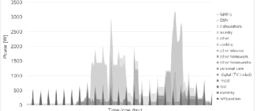
For each family, a weekly electricity consumption profile was used with a 10 minutes time step which proved to be adapted to represent residential electricity consumption [11]. The weekly profiles are created thanks to bottom-up method based on previously exposed work. The electrical consumption is linked to each activity of the occupant and the energy class of their appliances. Aggregating every consumptions allows to generate a stochastic electrical pattern for a full week. As the average of non-HVAC consumption of electricity in French households is about 2700 kWh/yr [12], two profiles are chosen below (1600 kWh/yr) and above (4500 kWh/yr) the mean. The study also uses annual lighting scenario for each family, depending on occupancy and time of the year to take into account the reduction of lighting during summer period. HVAC consumptions are added to the previous profiles to represent the consumption of Controlled Mechanical Ventilation (CMV) and of the additional space heating water pump when it is needed, according to the hydraulic configuration. The electrical consumption of the heat generation system is modeled in the µCHP model. An example of the daily aggregated consumption of the “high consumption” household for Tuesday is shown below:
Modeling of domestic hot water consumption
Similarly, domestic hot water profiles are generated with a 10 minutes time step and they are consistent with occupancy and activities. The water is tapped with a flow rate of 1.2 10-5 m3/s for each occupant using hot water. The profiles are generated for each of the two families. The “low consumption” household consumes 89 L/day of water at 60 °C while the “high consumption” one consumes 166 L/day of water at 60 °C. These values can be compared reasonably to those of the multiple studies cited in [13]
The Table 2 summarizes the characteristics of the two “families”: Table 2. Description of the two scenarios of occupants
Level of consumption High Low
Number of persons in the household 4 2 Consumption of non-HVAC electricity except lighting 4500 kWh/yr 1600 kWh/yr Quantity of tapped water at 60 °C per day 166 L/day 89 L/day Hydraulic configurations and controls
Three hydraulic configurations are compared in this paper. The term “hydraulic
configuration” means number of thermal storages and their type (SH or DHW storage). These configurations are based on µCHP manufacturers. All storage tanks are selected in some manufacturers’ catalogues to get real data such as geometry and insulation.
The emitters are always dimensioned for 60/50 °C temperature and nominal flow rate is adjusted for maximum heating needs. They are modeled with an equivalent radiator dynamic model and thermostatic radiator valve (TRV). The auxiliary burner can modulate its thermal power from 3.5 to 20 kW. It can deliver thermal power only if the Stirling engine has been working for more than 5 minutes. Two hysteresis cycles determine the temperature at which the Stirling engine and the auxiliary burner will start and stop.
Configuration 1 (C1)
The water exiting the µCHP system is directly sent to the emitters. A storage is present for DHW needs. The
auxiliary burner can help the SE only for SH needs as it is assumed that the engine is powerful enough to always manage DHW storage. Weather dependent setpoint (WDS) for space heating water is computed. DHW storage
temperature is constant. Multiple sizes of DHW storages are tested with an insulation of 4 cm.
Configuration 2 (C2)
A common storage is used for both DHW and SH needs. The DHW passes through the tank to exchange with the stored water. The stored water circulates across the emitters. The AB can help the SE for both DHW and SH needs as they are not differentiated in the tank. An
additional pump is needed and WDS is not possible as the stored water always needs to be at a high temperature to prepare DHW. Multiple sizes of storage are tested. It should be noted that the storage tank is very well insulated (13 cm).
Figure 2. Configuration with DHW storage only
Figure 3. Configuration with combi-storage
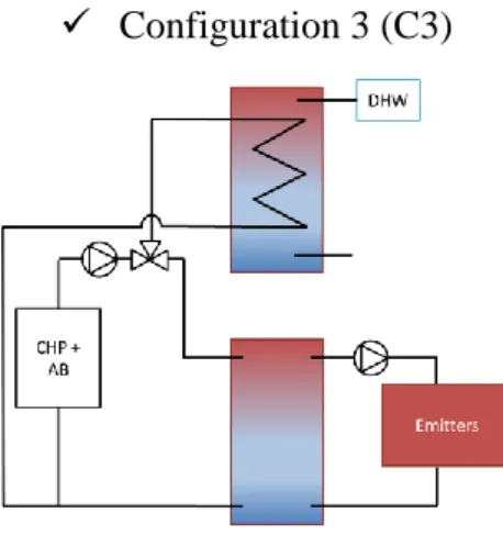
Configuration 3 (C3)
In this case, DHW and SH storage are separated. The 3-way valve controls which of the tanks is filled with hot water coming from the µCHP system. The AB can help the SE only for SH needs as it is assumed that the engine is powerful enough to always manage DHW storage. An additional pump is needed and WDS is possible as DHW and SH are physically separated. Multiple sizes of SH storage will be studied (DHW tank volume is fixed) with an insulation of 4 cm for each tank.
Table 3 summarizes the studied sizes of tanks for each hydraulic configuration. “Default” value is shown in bold characters.
Table 3. Description of the tested hydraulic configurations
Configuration/Tank sizes in litres DHW SH
1 160/200/400 -
2 450/600/750
3 160 100/200/400
Modeling of micro-cogeneration system
The 1 kWel + 7 kWth Stirling Engine is modeled thanks to the work of Bouvenot and Andlauer
[2] [14]. The semi-empirical model relies on experimental calibration and validation done at the laboratory of INSA Strasbourg. It was initially implemented as a TRNSYS type and it has been translated to Dymola environment for the purpose of this study. It represents the
transient and stationary performance of the Stirling Engine according to its operating conditions, especially the mass flow rate of cooling water (𝑚̇𝑐𝑤) return cooling water temperature (𝑇𝑐𝑤,𝑖). Stationary performances are given by correlations for fuel inlet
power (𝑃𝑓𝑢𝑒𝑙), delivered thermal (𝑄̇𝐻𝑋) and electrical (𝑃𝑔𝑟𝑜𝑠𝑠) power, such as: 𝑃𝑓𝑢𝑒𝑙 = 𝑃𝑓𝑢𝑒𝑙𝑛𝑜𝑚+ 𝑎 (𝑇
𝑐𝑤,𝑖 − 𝑇𝑐𝑤,𝑖𝑛𝑜𝑚) + 𝑏 (𝑚̇𝑐𝑤− 𝑚̇𝑐𝑤𝑛𝑜𝑚) (1)
𝑄̇𝐻𝑋 = 𝑄̇𝐻𝑋𝑛𝑜𝑚+ 𝑐 (𝑇
𝑐𝑤,𝑖− 𝑇𝑐𝑤,𝑖𝑛𝑜𝑚) + 𝑑 (𝑚̇𝑐𝑤− 𝑚̇𝑐𝑤𝑛𝑜𝑚) (2)
𝑃𝑔𝑟𝑜𝑠𝑠 = 𝑃𝑔𝑟𝑜𝑠𝑠𝑛𝑜𝑚 + 𝑒 (𝑇𝑐𝑤,𝑖− 𝑇𝑐𝑤,𝑖𝑛𝑜𝑚) + 𝑓 (𝑚̇𝑐𝑤− 𝑚̇𝑐𝑤𝑛𝑜𝑚) (3)
For start-up and stop phases, calibrated exponential correlations model evolution of fuel, thermal and electrical power as a function of time. Delays for electrical and thermal production after the beginning of the start-up are also taken into account.
The auxiliary burner is modeled thanks to state of the art modulating boiler [15]. It is also based on experimentation and performances depends on the same parameters and part load ratio (PLR). The auxiliary burner and the reference case boiler have a nominal power of 24 kWth. Finally, auxiliary power for the pump and controls electrical consumptions are modeled
depending on operating conditions.
Primary energy and reference configuration
The primary energy factor are 1 for natural gas and 2.58 for electricity the value according to the French thermal regulation. The “reference” configuration used to compute primary energy savings is based on a condensing boiler with a 160 L DHW storage and a WDS for SH.
RESULTS
The different configurations can be compared thanks to various criteria. For
micro-cogeneration, self-consumption (share of the produced electricity which is self-consumed) is a significant criterion as it is today in the French context better to consume electricity on-site than export it to the grid. Self-production (share of the electricity needs which is directly covered by the micro-cogeneration) is also an important criterion as it means that the building is not importing electricity from the grid for a part of its needs.
Figure 5 shows self-consumption and self-production ratios for three levels of building insulation and three hydraulic configurations and for “high” occupancy profile. For “low” occupancy profile, two hydraulic configurations and two levels of insulation are tested. Tank volumes are set to the “default” values. It can be seen that self-consumption mainly depends on the electricity load curve of the buildings. The simulations with “Low” electrical profile leads to slightly lower self-consumption ratio (42-47 %) than “High” profile (61-73 %). Figure 5 also shows the best self-consumption ratio is achieved for the building with higher thermal needs with hydraulic configuration No. 3. For both “Middle” and “Low” building cases, the best self-consumption ratios are reached for configuration No. 1. Detailed analysis of the simulations results shows that for these cases, more thermal storage leads to drastically shift the thermal load curve of the building so that thermal and electricity needs are less concomitant. In the best case, for the “Low” occupancy profile with “High” thermal needs, self-production ratio can reach 34 %.
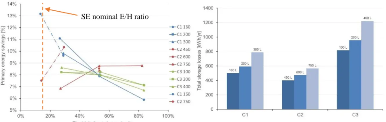
Figure 7 shows Primary energy savings (PES) for various tank sizes, hydraulic configurations building insulations and occupancy profiles. X-axis represents E/H demand ratio of the building. The lowest the E/H demand ratio is (on the left) the highest the thermal needs are and the lowest the electricity needs are. “Low” occupancy profiles are shown in dotted lines. Figure 7 shows that the “best” point for primary energy savings (PES) seems to be achieved
Figure 5. Self-consumption and self-production for various configurations
Figure 6. Total storage losses for “Middle” building case and “High” occupancy profile
Figure 7. Primary energy savings for various configurations SE nominal E/H ratio
for E/H demand ratio close to the nominal production E/H ratio of the SE (1 kWel/7 kWth so
14 %).
Presence of thermal storage for space heating (C2 and C3) allows to reach higher PES for low thermal needs (on the right of the chart) as it allows to longer the Stirling Engine operating cycles. However, for building with high thermal needs, thermal storage for SH is not needed because it does not help to meet higher savings.
Configuration No. 2 shows low storage heat losses (see Figure 6) because of its higher insulation. For low thermal needs, high insulation and high storage capacity are primordial because losses can accounts for a large part of the total thermal needs and high storage volume lengthen operating cycles.
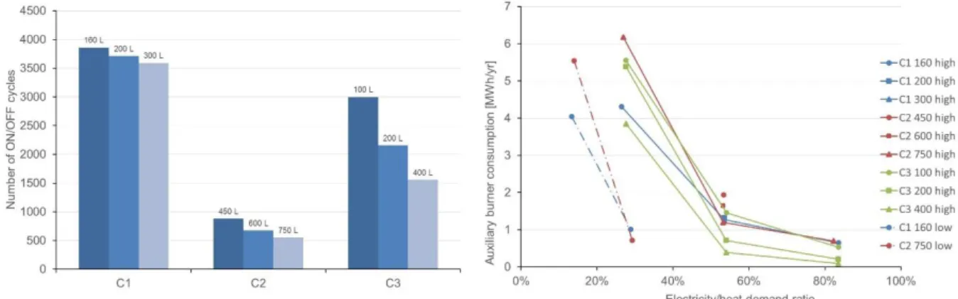
For “Middle” and “Low” building cases, using properly sized thermal storage for space heating demand enables to lower the use of the auxiliary burner as can be seen on figure 9 and consequently raises the share of the Stirling Engine in total heat production.
For “High” building case with configuration No. 2 as both SH and DHW needs are to be handled in the same tank and storage temperature setpoint is always higher than for other configurations (no WDS), the SE is not powerful enough when the tank is discharged and auxiliary burner is often needed.
In every cases, configuration without SH storage leads to increased numbers of Stirling Engine ON/OFF cycles as expected. This could lead to less efficient production but, as return temperature is lower than for storage configurations (2 and 3), global efficiency remains correct: both electrical and thermal efficiency increase for low temperature of returning water. If the number of operating cycles is critical for life expectancy of the µCHP, C2 may be preferred as the larger volume enables the longest operating cycles.
DISCUSSION
This paper shows that design of hydraulic integration clearly influences performances and operating conditions of a SE-µCHP system. First, it seems that DHW storage should be chosen close to the daily needs of hot water as increasing its size does not really enhance performance but grow thermal losses. In the case of this 1 kWel SE, the best configuration for buildings with
high heating needs seems to be without SH storage. Thermal needs are large enough to allow long operating cycles and storage only creates heat losses. However, for buildings with low thermal needs, SH storage leads to higher primary energy savings as it allows longer operating cycles and then more electricity to be produced. It also appears that the best primary energy savings and self-production are reached for buildings for which E/H demand ratio is close to the nominal E/H ratio of the µCHP.
Figure 8. Auxiliary burner consumption for various configurations
Figure 9. Number of ON/OFF cycles for “middle” building case and “high” occupancy profile
From a strict economic point of view, solutions without thermal storage may still be preferred if the additional cost for storage tank cannot be refunded during the lifecycle of the µCHP system: this is why a complete economic analysis should be carried on.
Parameters that could possibly influence the results are the settings of system controls. For example, larger hysteresis bands may be tested to enable longer operating cycles. Management of auxiliary burner could be explored as well as storage tank piping configurations. Exhaustive sensitivity analysis of the results over occupant’s electrical and thermal needs should be assessed. Finally, the presented methodology should be extended to explore the best couples of various µCHP technologies over different buildings types and occupations.
ACKNOWLEDGEMENT
The authors would like to thank Efficacity for its support in the achievement of this project.
REFERENCES
[1] I. Beausoleil-Morrison, "Experimental Investigation of Residential Cogeneration Devices and Calibration of Annex 42 Models," IEA, 2007.
[2] J.-B. Bouvenot, B. Andlauer, P. Stabat, D. Marchio and B. Flament, "Gas Stirling engine micro CHP boiler experimental data driven model for building energy simulation," Energy and Buildings, no. 84, pp. 117-131, 2014.
[3] V. Dorer, R. Weber and A. Weber, "Performance assessment of fuel cell micro-cogeneration systems for residential buildings," Energy and Buildings, pp. 1132-1146, 2005.
[4] K. Alanne, N. Söderholm, K. Sirén and I. Beausoleil-Morrison, "Techno-economic assessment and optimization of Stirling engine micro-cogeneration systems in residential buildings," Energy Conversion and Management, no. 51, pp. 2635-2646, 2010.
[5] V. Dorer and A. Weber, "Energy and CO 2 emissions performance assessment of residential micro-cogeneration systems with dynamic whole-building simulation programs," Energy Conversion and Management, no. 50, pp. 648-657, 2008.
[6] Dassault Systèmes, Dymola User Manual, 2014.
[7] T. Berthou, "Development of building models for load curve forecast and design of energy optimization and load shedding strategies," 2013.
[8] M. Wetter, W. Zuo, T. S. Nouidui and W. Pang, "Modelica Buildings Library," Journal of Building Performance Simulation, vol. 7, 2014.
[9] U. Wilke, "Probabilistic Bottom-up Modelling of Occupancy and Activities to Predict Electricity Demand in Residential Buildings," 2013.
[10] Vorger, Study of the influence of the inhabitants behavior on the energy performance of buildings, Paris: Ecole Nationale Supérieure des Mines de Paris, 2014.
[11] A. Hawks and M. Leach, "Impacts of temporal precision in optimisation modelling of micro-Combined Heat and Power," Energy, p. 1759, 2004.
[12] Enertech, "Mesure de la consommation des usages domestiques de l’audiovisuel et de l’informatique - Projet REMODECE," 2008.
[13] M.-J. Lagogue, "PACTE ECS Les besoins d'ECS en habitat," COSTIC, 2014.
[14] B. Andlauer, Optimisation systémiques de micro-cogénérateurs intégrés au bâtiment, Paris: Ecole Nationale Supérieure des Mines de Paris, 2011.
[15] R. Bonabe de Rougé, Modélisation de systèmes de chauffages en résidentiel, Strasbourg: INSA Strasbourg, 2014.