Faculty de g&iie
Departement de genie civil
FLEXURAL BEHAVIOUR OF REINFORCED CONCRETE BEAMS
STRENGTHENED WITH NEAR SURFACE MOUNTED FRP BARS
COMPORTEMENT EN FLEXION DE POUTRES ENBETON
ARME RENFORCEES PAR DES ARMA TURES EN PRF
ENCASTREES PRES DE LA SURF A CE
These de doctorat es sciences appliquees Speciality : genie civil
Jury: Claude Lupien Kenneth Neale Brahim Benmokrane Ehab El-Salakawy Omar Chaallal Renata Kotynia President Rapporteur Directeur de recherche Codirecteur Examinateur Examinateur
Shehab Monir SOLIMAN
1*1
Archives Canada Published Heritage Branch 395 Wellington Street Ottawa ON K1A0N4 Canada Archives Canada Direction du Patrimoine de I'edition 395, rue Wellington Ottawa ON K1A0N4 CanadaYour file Votre reference ISBN: 978-0-494-48582-8 Our file Notre reference ISBN: 978-0-494-48582-8
NOTICE:
The author has granted a non-exclusive license allowing Library and Archives Canada to reproduce, publish, archive, preserve, conserve, communicate to the public by
telecommunication or on the Internet, loan, distribute and sell theses
worldwide, for commercial or non-commercial purposes, in microform, paper, electronic and/or any other formats.
AVIS:
L'auteur a accorde une licence non exclusive permettant a la Bibliotheque et Archives Canada de reproduire, publier, archiver,
sauvegarder, conserver, transmettre au public par telecommunication ou par Plntemet, prefer, distribuer et vendre des theses partout dans le monde, a des fins commerciales ou autres, sur support microforme, papier, electronique et/ou autres formats.
The author retains copyright ownership and moral rights in this thesis. Neither the thesis nor substantial extracts from it may be printed or otherwise reproduced without the author's permission.
L'auteur conserve la propriete du droit d'auteur et des droits moraux qui protege cette these. Ni la these ni des extraits substantiels de celle-ci ne doivent etre imprimes ou autrement reproduits sans son autorisation.
In compliance with the Canadian Privacy Act some supporting forms may have been removed from this thesis.
Conformement a la loi canadienne sur la protection de la vie privee, quelques formulaires secondaires ont ete enleves de cette these.
While these forms may be included in the document page count,
their removal does not represent any loss of content from the thesis.
Bien que ces formulaires
aient inclus dans la pagination, il n'y aura aucun contenu manquant.
As we move into the twenty-first century, the renewal of our lifelines or deterioration of infrastructure becomes a topic of critical importance. The structures may have to carry larger loads, require change in building use, suffer steel corrosion problems, or errors made during the design or construction phases so that the structure may need to be repaired or strengthened before it can be used. The use of fiber reinforced polymers (FRP) in the last few years in various engineering application, forums and configuration offers an alternative design approach for the construction of new concrete structures and the rehabilitation of existing ones. The use of FRP materials for external strengthening of reinforced concrete (RC) structures has emerged as one of the most exciting and promising technologies in material and structural engineering. Externally bonded FRP reinforcement is relatively unprotected against impact, vandalism or severe environmental conditions. Their structural performance can be greatly affected by these drawbacks. But if the composite material is placed in slots inside the concrete cover some of these drawbacks can be overcome. This method is designated by Near Surface Mounted (NSM) method. Therefore, the presented work is carried out using this advantageous strengthening technique utilizing the non-corrodible FRP materials.
My research involved both experimental and analytical investigations on the use of FRP systems for strengthening concrete structures using NSM techniques. The main objectives of my research were to (1) develop/utilize an NSM system composed of FRP bars and adhesives, (2) investigate the bond performance for the proposed NSM system, (3) investigate the effect of freeze and thaw cycles on the of the new proposed system, (4) study the flexural behaviour of RC beams strengthened with NSM FRP bars, (5) develop an analytical model using non-linear finite element analysis (ADINA) taking into consideration the interfacial behaviour between the concrete and FRP bars and (6) establish design recommendations for the use of FRP bars for the NSM method. To achieve these objectives, the research program was divided into two parts. The first part included the experimental work while the second part included the analytical work. The first part consisted of two phases. The first phase included the pullout testing of 76 C-shape
flexural strengthened concrete beams using the NSM method. The second part included developing an analytical model to be used in a non-linear finite element program and to analyze and predict the behaviour of concrete beams strengthened for flexure using NSM FRP bars. The efficiency and accuracy of the model was verified by comparing its results to the experimental results. The developed analytical model was used to study the effect of different parameters. Test results are presented in terms of deflection, strain in the concrete, steel and FRP and modes of failure. Test results showed the superior performance of the proposed NSM FRP/adhesive system. The NSM system is able to increase both the stiffness and flexural capacity of concrete beams by approximately
100% over the unstrengthened one. The FEM was able to predict of the behaviour of the strengthened beams in flexure with NSM. Based on the experimental and analytical study, useful conclusions and recommendations for flexural strengthening with NSM FRP were provided.
Alors que nous entrons dans le XXIeme siecle, la degradation des infrastructures devient un sujet d'une importance cruciale. Les structures doivent supporter des charges plus grandes et subir des changements d'utilisation. En plus de cela s'ajoute les problemes de corrosion de l'acier, des erreurs de conception et de construction, ce qui souvent necessitent que la structure soit reparee ou renforcee, des fois merne avant sa mise en service. L'utilisation de polymeres renforces de fibres (PRF) dans les dernieres annees dans divers domaines d'ingenierie a permis une avancee technologique, et leur utilisation dans la construction de nouvelles structures en beton ainsi que la rehabilitation des anciennes. L'utilisation de materiaux en PRF pour le renforcement externe des structures en beton arme est une technologie des plus prometteuses dans l'ingenierie structurale ou de materiaux. Cependant le renforcement par collage externe de PRF n'offre pas une bonne protection contre les chocs, le vandalisme ou les conditions environnementales severes, ce qui pourraaient affecter les performances structurales des elements rehabilites. Ces inconvenients peuvent etre surmontes si le PRF est insere dans des rainures realisees dans le recouvrement de beton. Cette methode est appelee « mise en place d'Armatures Encastrees Pres de la surface (AEPS)». Le present travail s'articule autours de cette technique de renforcement utilisant des materiaux non corrodables.
Mes travaux de recherches se focalisent sur l'utilisation des AEPS en PRF pour le renforcement des structures, et cela d'un point de vue experimental et analytique. Les principaux objectifs de mes recherches sont: (1) developper/utiliser un systeme d'AEPS compose de barres en PRF et d'adhesif, (2) etudier les performance d'adherence du systeme propose, (3) etudier l'effet des cycles gel-degel sur le systeme propose, (4) l'etude du comportement en flexion de poutres en beton arme, renforcees avec des barres d'AEPS en PRF, (5) developper un modele analytique utilisant des methodes non-lineaires d'analyse par elements finis (logiciel ADINA) en tenant compte du comportement de 1'interface beton-barres en PRF, et (6) mettre en place des recommandations de calcul pour l'utilisation des barres en PRF comme AEPS.
premiere partie comprenait les travaux experimentaux tandis que la deuxieme comprenait des travaux d'analyse. La premiere partie elle meme etait constitute de deux phases. La premiere phase comprenait des essais d'arrachement direct de blocs de beton en forme de « C », dont 16 blocs conditionnes dans une chambre environnementale. Alors que la deuxieme phase comportait des essais de flexion 20 poutres en beton arme, renforcdes par des AEPS en PRF.
La deuxieme partie a consiste au developpement d'un modele analytique non-lineaire par elements finis de facon a pouvoir analyser et predire le comportement en flexion de poutres en beton arme, renforcees par des AEPS en PRF. L'efficacite et la precision du modele ont ete verifiees en comparant ses resultats analytiques aux rdsultats experimentaux. Le modele analytique developpe a ete utilise pour etudier l'effet de differents parametres. Les resultats des tests sont presentes en termes de deflexion, de contraintes dans le beton, l'acier et le PRF et les modes de rupture.
Les resultats des essais ont demontre les bonnes performances du systeme armatures PRF/adhesif propose, ce dernier a permit d'augmenter a la fois la rigidite en flexion et la resistance des poutres en beton d'environ 100% par rapport a la poutre non renforcee. L'analyse par elements finis a ete en mesure de predire le comportement en flexion des poutres renforcees avec des AEPS en PRF. Base sur ces travaux, des conclusions et des recommandations utiles concernant le renforcement en flexion avec des AEPS en PRF ont ete fournis.
Mots cles: polymeres de fibres, PRFC, PRFV, arme, armatures encastrees pres de la surface, AEPS, elements finis, comportement en flexion
Praise be to Allah Almighty and Peace be upon His Prophet Muhammad
I wish to take the opportunity to express my acknowledgements to those whom without their assistance this thesis work could not have been done.
I would like to express my deepest appreciation to my supervisor Professor Brahim Benmokrane who introduced me to the area of research of fibre composites. Without exaggeration, this work could not have been done without his guidance, invaluable advice, helpful discussions and constant encouragement.
I am deeply grateful to my co-supervisor Prof. Ehab El-Salakawy for his constant support and continuous encouragement and guidance, not only on the academic side but also on the personal level. I am also most grateful to him for his help in making my settling in Canada a reality. He helped me in overcoming obstacles that I encountered during my first year in Canada.
The financial support provided by the Natural Sciences and Engineering Research Council of Canada (NSERC), and the Network of Centres of Excellence on Intelligent Sensing of Innovative Structures (ISIS Canada) Pultrall and Hilti Canada are gratefully acknowledged.
Many thanks to Mr. Francois Ntacorigira, Simon Sindayigaya, Nicolas Simard and other technical staff at the Structures Laboratory, Department of Civil Engineering, Universite de Sherbrooke, for their technical assistance during the fabrication, construction and testing of the specimens.
Many thanks also go to all my colleagues and friends in the Department of Civil Engineering at the Universite de Sherbrooke, in particular Dr. Hussein Abd El-Baky for his great help in the analytical part of my study.
I cannot end my acknowledgements without expressing my profound and eternal gratitude to: my father, my mother, my sister. I owe my loving thanks to my wife Nermine and my lovely son Hussein who continuously encouraged me to strive for
success in my life.
ABSTRACT i RESUME iii ACKNOWLEDGMENTS v
TABLE OF CONTENTS vi LIST OF FIGURES xi LIST OF TABLES xvi
Chapter 1 INTRODUCTION
1.1. General 1 1.2. Research Objective 3 1.3. Methodology 5 1.4. Thesis Structure 6 Chapter 2 L I T E R A T U R E R E V I E W 2.1. General 8 2.2. Fibre Reinforced Polymer (FRP) 92.2.1. Reinforcing fibres 9
2.2.2. Resins 11 2.2.3. FRP reinforcement products 12
2.3. Near Surface Mounted (NSM) Techniques 13
2.3.1. Bond behaviour 15 2.3.2. Flexural strengthening 23
2.3.2.1. Modes of failure for flexural strengthening 30 2.3.2.2. Design equation for flexural strengthening 31
2.3.3. Flexural strengthening with prestressed NSM bars 35
2.3.4. Shear strengthening 36
2.3.4.1. Modes of failure for shear strengthening 37 2.3.4.2. Design equation for shear strengthening 38
3.1. General 43 3.2. Experimental Program 43
3.3. Phase I: Bond Behaviour of NSM-FRP Bars in Concrete 45
3.3.1. Pullout test specimens 43
3.3.1.1. Stage one: Bond characteristics 45 3.3.1.2. Stage two: Effect of freeze/thaw cycles 48
3.3.2. Fabrication of pullout specimens 50
3.3.3. Cutting the grooves 51 3.3.4. Installation of the NSM-FRP bar 53
3.3.5. Test setup 53 3.4. Phase II: Flexural Strengthening of RC Beams Using NSM-FRP Bars 55
3.4.1. Beam test specimens 54 3.4.2. Fabrication of beam specimens 57
3.4.3. Strengthening procedures 58
3.4.3.1. Cutting the groove 58 3.4.3.2. Installation of the FRP bar 58
3.4.4. Instrumentations 60
3.4.4.1. Strain monitoring 60 3.4.4.2. Deflection monitoring 61 3.4.4.3. Slip monitoring 62 3.4.4.4. Crack width monitoring 62
3.4.5. Test setup and procedure 63
3.5. Material Properties 65 3.5.1. Concrete 65 3.5.2. Steel bars 66 3.5.3. FRP bars 67 3.5.4. Adhesives 68
T E S T R E S U L T S
4.1. General 70 4.2. Stage One: Bond Characterization 70
4.2.1. Modes of failure 71
4.2.1.1. Specimens with epoxy adhesive 71 4.2.1.2. Specimens with cement adhesive 76
4.2.2. Effects of different parameters on the bond characterization 78
4.2.2.1. Effect of bonded length 78 4.2.2.2. Effect of groove size 78
4.3. Stage Two: Effect of Freeze/Thaw Cycles 79
4.3.1. Failure load 79 4.3.2. Modes of failure 81 4.3.3. Strain distribution 85 4.4. Bond-Slip Analysis 89
4.4.1. Average bond stress-slip relationship .89 4.4.2. Local bond stress-slip relationship 94
4.5. Nonlinear Regression Analysis 100
4.6. Summary 102
Chapter 5 FLEXURAL STRENGTHENING: ANALYSIS AND
D I S C U S I O N O F T E S T R E S U L T S 5.1. General 104 5.2. Flexural Strengthening 104 5.2.1. Series A 106 5.2.2. Series B I l l 5.2.3. Series C 116 5.3. Effects of Different Parameters on the Behaviour of the Strengthened Beams... 126
5.3.1. Effect of steel reinforcement ratio 126
5.3.4. Effect of NSM-FRP axial stiffness (EA) 127
5.3.5. Effect of NSM-FRP bar type 127
5.4. Summary 128
Chapter 6 F I N I T E E L E M E N T M O D E L L I N G
6.1. General 129 6.2. Materials Modelling 129
6.2.1. Concrete modelling 129 6.2.2. Steel reinforcement modelling 133
6.2.3. FRP reinforcement modelling 134 6.2.4. Epoxy adhesive modelling 134 6.2.5. Interface modelling 134 6.3. Finite Element Analysis (FEA) Modelling 134
6.4. Finite Element Results and Discussion 136 6.4.1. Validation of the proposed finite element model 139
6.4.2. Parametric study 143
6.4.2.1. Effect of steel reinforcement ratio 143 6.4.2.2. Effect of concrete compressive strength 144 6.4.2.3. Effect of axial stiffness (EA) of NSM-FRP bars 147
6.4.2.4. Effect of bonded length 149
Chapter 7 C O N C L U S I O N S A N D R E C O M M E N D A T I O N S
7.1. General 141 7.2. Experimental Results 141
7.2.1. Bond characteristics: Pullout tests 141 7.2.2. Flexural strengthening: Beam tests 142
7.3. FEA Results 143 7.4. Recommendations for Future Work 144
Fig. 1.1. Research program 6 Fig. 1.2. Thesis layout 7 Fig. 2.1. Grouting of steel bars in bridge deck slab, Finland (Asplund 1949) 14
Fig. 2.2. Steps of instillation of NSMFRP 15 Fig. 2.3. Test specimen, (Lorenzis et al. 2002) 16 Fig. 2.4. Tested specimens, (De Lorenzis andNanni 2002) 19
Fig. 2.5. Strain distribution along the CFRP bonded length, (Lorenzis and Nanni 2002).20 Fig. 2.6. Slip distribution along the CFRP bonded length, (Lorenzis and Nanni 2002).. .21 Fig. 2.7. Bond stress distribution along the CFRP bonded length, (Lorenzis and Nanni
2002) 21 Fig. 2.8. Local bond slip along the CFRP bonded length, (Lorenzis and Nanni 2002) 21
Fig. 2.9. Specimen of pullout-bending test, (Cruz et al. 2004) 22 Fig. 2.10. Influence of bond length on the peak pullout force, (Cruzetal. 2004) 22
Fig. 2.11. Influence of concrete strength on the peak pullout force, (Cruz et al. 2004)....22
Fig. 2.12. Test Specimen, (Hassan and Rizkalla 2003) 24 Fig. 2.13. Load-deflection behaviour of test specimens with embedded length (150-850
mm), (Hassan and Rizkalla 2003) 25 Fig. 2.14 .Load-deflection behaviour of test specimens with embedded length (950-1200
mm), (Hassan and Rizkalla 2003) 25 Fig. 2.15. FRP strengthening schemes, (El-Hacha and Rizkalla 2004) 27
Fig. 2.16. Load-deflection curve for strengthened beams with NSM CFRP strips and
rebar, (El-Hacha and Rizkalla 2004) 28 Fig. 2.17. Load-deflection curve for strengthened beams with NSM and externally
bonded CFRP strips, (El-Hacha and Rizkalla 2004) 29 Fig. 2.18 Load-deflection curve for strengthened beams with NSM CFRP and GFRP
strips, (El-Hacha and Rizkalla 2004) 29 Fig. 2.19. Principles for strengthening in bending, (Taljsten et al. 2003) 31
Fig. 2.20. Test set-up and dimensions of tested beams, (Taljsten et al. 2003) 33 Fig. 2.21. Load-deflection curve for the tested beams, (Taljsten et al. 2003) 32
Fig. 2.23. Flexural strengthening with NSM prestressing, (Nordin and Taljsten 2006).. .36
Fig. 2.24. Installation of CFRP for shear strengthening, (Nanni et al. 2004) 37 Fig. 2.25. Modes of failure of shear strengthening, (De Lorenzis and Nanni 2001c) 38
Fig. 2.26. Elevation of timber beam with GFRP bars for shear strengthening, (CSA,
2006) 42 Fig. 3.1. Pullout test specimen 46
Fig. 3.2. Specimens in the environmental chamber and instrumentations 49
Fig. 3.3. Freeze/thaw cycles 50 Fig. 3.4. Pullout specimens in the formwork 51
Fig. 3.5. Cutting the groove for the pullout test specimens 51
Fig. 3.6. Installation of NSM-FRP bar 52
Fig. 3.7. Pullout test setup 53 Fig. 3.8. Upper and lower steel plates 53
Fig. 3.9. Dimensions and reinforcement details of the beam test specimen 55
Fig. 3.10. Steel reinforcement cages in formwork 57
Fig. 3.11. Concrete casting 57 Fig. 3.12. Cutting the groove 58 Fig. 3.13. Chopping the concrete 58 Fig. 3.14. NSM-FRP installation 59 Fig. 3.15. Instrumentations layout 60 Fig. 3.16. Strain gauges on steel bars 61 Fig. 3.17. Deflection monitoring 62 Fig. 3.18. NSM-FRP slip monitoring 62 Fig. 3.19. Crack width monitoring 63 Fig. 3.20. Data acquisition system 6000 63
Fig. 3.21. Beam test setup 64 Fig. 3.22. Concrete compression test 66
Fig. 3.23. Concrete splitting test 66 Fig. 3.24. Stress strain curve for the concrete cylinders 66
Fig. 3.27. Tensile failure for CFRP 9.5 mm-diameter 68 Fig. 3.28. Slippage failure for CFRP 12.7 mm-diameter ..68
Fig. 3.29. The two-component adhesive package 69 Fig. 4.1. Modes of failure for specimens with NSM-CFRP bar and epoxy adhesive 75
Fig. 4.2. Modes of failure for specimens withNSM-GFRP bar and epoxy adhesive 76 Fig. 4.3. Modes of failure for specimens with NSM-CFRP bar and cement adhesive 77 Fig. 4.4. Pullout load for epoxy and cement adhesive for specimens with groove size of
1.5 times the NSM bar diameter 77 Fig. 4.5. Pullout load at failure versus bonded length for specimens with epoxy
adhesive 78 Fig. 4.6. Pullout load for the tested specimens 80
Fig. 4.7. Modes of failure for the tested conditioned specimens with epoxy adhesive.. ..83 Fig. 4.8. Mode of failure for the tested conditioned specimens with cement adhesive 83
Fig. 4.9.. Average bond stress-slip for C/9.5-E-1.50-12 and D-E-l.5-12 84 Fig. 4.10. Average bond stress-slip for C/9.5-E-1.50-18 and D-E-l.5-18 84 Fig. 4.11. Strain distribution in FRP bars during freeze/thaw cycling for D-E-l.
5-12 .' 86 Fig. 4.12. Strain distribution in the FRP bars during freeze/thaw cycling for D-E-l
.5-12 86 Fig. 4.13. Strain distribution in athaw cycle for D-E-l.5-12 87
Fig. 4.14. Strain distribution in a freeze cycle for D-E-l .5-12 87 Fig. 4.15. Strain distribution during freeze/thaw cycling for D-C-l .5-12 88
Fig. 4.16. Strain distribution during freeze/thaw cycling for D-C-l.5-12 88
Fig. 4.17. Average bond stress-slip for C/9.5-E-1.50-12 90 Fig. 4.18. Average bond stress-slip for C/9.5-E-1.50-18 90 Fig. 4.19. Average bond stress-slip for C/9.5-E-2.00-12 91 Fig. 4.20. Average bond stress-slip for C/9.5-E-2.00-18 91 Fig. 4.21. Average bond stress-slip for C/12.7-E-2.00-18 92 Fig. 4.22. Average bond stress-slip for C/9.50-C-1.50-12 92 Fig. 4.23. Average bond stress-slip for C/9.50-C-1.50-18 93
Fig. 4.25. Strain distribution along the bar bonded length for specimen
C/9.5-E-1.50-48... 96 Fig. 4.26. Strain distribution along the bar bonded length for specimen G/12.7-E-2.0-36
97 Fig. 4.27. Bond stress distributions along the bar bonded length for specimen
C/9.5-E-1.50-48 98 Fig. 4.28. Bond stress distributions along the bar bonded length for specimen
G/9.5-E-2.0-36 98 Fig. 4.29. Local bond stress-slip at different locations along the bar bonded length for
specimen C/9.5-E-1.50-48 99 Fig. 4.30. Local bond stress-slip at different locations along the bar bonded length for
specimen G/12.7-E-2.0-36 99 Fig. 4.31. Comparisons between load predictions from the regression models and the
experimental results 101 Fig. 5.1. Load-deflection behaviour for a strengthened and unstrengthened beam 105
Fig. 5.2. Load-deflection curve for series A 107 Fig. 5.3. Load-strain relationship for concrete and steel for series A 108
Fig. 5.4. Load-CFRP tensile strain at mid span for series A 108 Fig. 5.5. Crack pattern and mode of failure for series A 109
Fig. 5.6. Load-deflection curve for series B 112 Fig. 5.7. Load-strain relationships for concrete and steel for series B 113
Fig. 5.8. Load-CFRP tensile strain at mid span for series B 113
Fig. 5.9. Compression failure for B0 114 Fig. 5.10. Concrete cover split for Bl 114 Fig. 5.11. Concrete cover split for B2 114
Fig. 5.12. Load-deflection curve for beams C I , C2, C3 and C4 117
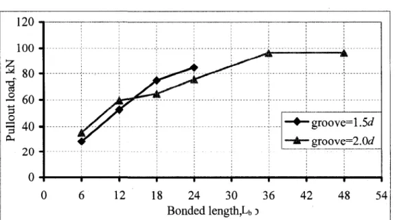
Fig. 5.13. Mid-span CFRP strain for beams CI, C2,C3 and C4 118 Fig. 5.14. Failure load for specimens with groove size 1.5d and 2S)d 119 Fig. 5.15. Load-deflection curves for beams C4 and C7 with bonded length 60d 120
Fig. 5.18. Load-deflection curve for series C 122 Fig. 5.19. NSM-FRP strain distribution for beam CIO 123
Fig. 5.20. NSM-GFRP strain distribution for beam CI 1 124 Fig. 6.1. Uni-axial stress-strain relationship used for the concrete model 130
Fig. 6.2. Biaxial concrete compressive failure envelope 132 Fig. 6.3. Tri-axial concrete compressive failure envelope 132 Fig. 6.4. Three-dimensional tensile failure envelope of concrete model 133
Fig. 6.5. Stress-strain relationship for steel 133 Fig. 6.6. Stress-strain relationship for FRP 134 Fig. 6.7. Local bond stress-slip profile 135 Fig. 6.8. A 20-node, 3-D solid element 136 Fig. 6.9. Global displacement degrees of freedom (DOF) 137
Fig. 6.10. A truss element generated into 3-D solid elements 138 Fig. 6.11. Types of elements used for the strengthened beams 138 Fig. 6.12. Comparison between numerical and experimental load-deflection relationships
for series B 140 Fig. 6.13. Comparison between numerical and experimental load-deflection relationships
for series C 141 Fig. 6.14. NSM-FRP strains for beam C3 142
Fig. 6.15. Effect of the steel reinforcement ratio on load-strain relationships 143 Fig. 6.16. Effect of reinforcement ratio (ps) on debonding load and strain 144
Fig. 6.17. Effect of concrete compressive strength on load deflection behaviour 146 Fig. 6.18. Effect of concrete compressive strength on FRP debonding strain 146
Fig. 6.19. Effect of concrete compressive strength on failure load 147
Fig. 6.20. Effect of axial stiffness on failure load 148 Fig. 6.21. Effect of axial stiffness on FRP debonding strain 148
Table 2.1. Mechanical properties of fibres, (ISIS CANADA 2007a) 11 Table 2.2. Typical properties of thermosetting resins, (ISIS CANADA 2007a) 12
Table 2.3. Test matrix for tested specimens (El-Hacha and Rizkala 2004) 27
Table 3.1. Description of test specimens for bond characteristics 47 Table 3.2. Description of test specimens for the effect of freeze/thaw cycles 49
Table 3.3. Description of test specimens for the flexural strengthening 57
Table 3.4. Mix composition of the used concrete 65 Table 3.5. Mechanical properties of the reinforcing bars 67
Table 3.6. Material specifications of adhesives (Hilti 2006) 69
Table 4.1. Test results for the bond characterization 73 Table 4.2. Test results for the freeze/thaw cycles effects 78
Table 5.1. Test results for series A 110 Table 5.2. Test results for series B 115 Table 5.3. Test results for series C 125 Table 6.1. Comparison of experimental and numerical results for series B and C 141
1.1. General
Since the first structures were formed, whether by nature or early human beings, they have been plagued by deterioration and destruction. Deterioration and destruction could happen due to environmental effects and improper use or maintenance of these structures. These are laws of nature that affect even the most modern structures. Therefore, it is important to have durable structures with long sustained life and low maintenance effort and costs. Maintenance is not only about costs but also a necessity to keep the structure at a specific high performance level, which includes load carrying capacity, serviceability, durability, function and aesthetic appearance. A structure that fulfill all demands of load carrying capacities must, at the same time, satisfy the durability demands or satisfy the society's demands for aesthetic appearance. Absence or incorrect maintenance will, in most cases, increase the speed of the degradation process and, therefore, lower the performance of the structure. The regular maintenance and repair of the different elements of any structure is always needed to restore the original performance of that structure. A reinforced concrete (RC) structure must have a long life. During this time duration, its carrying capacity, use, performance and aesthetic appearance could be changed. This change could be from the owners, users or surrounding society. To meet the changed demands, the RC structure needs to be upgraded or strengthened to increase its life time, durability and reliability. A structure with satisfactory load capacity, aesthetic appearance, and durability might not fulfill the function demands. To meet changed demands, a structure may be upgraded, which furthermore can be a way to increase life, durability and reliability of the structure.
As we moved into the twenty-first century, the renewal of our lifelines or deterioration of infrastructure becomes a topic of critical importance. The structures may have to carry larger loads, require change in building use, suffer steel corrosion problems, or errors made during the design or construction phases so that the structure may need to be repaired or strengthened before it can be used.
The requirement to repair and strengthen old concrete structures is increasing in the last decade. If one considers the capital that has been invested in existing infrastructures, then it is not always economical to replace an existing structure with a new one. The challenge must be taken to develop relatively simple measures to keep or increase a structure performance level through its life. It is important to analyze the problem to be able to select the most suitable method. The improper choice of an inappropriate repair or strengthening method can even worsen the structure's function. In comparison to building a new structure, strengthening an existing one is often more complicated since the structural conditions are already set. In addition, it is not always easy to reach the areas that need to be strengthened. Traditional methods have been used as strengthening techniques for concrete structure, such as: different kinds of reinforced overlays, shotcrete or post-tensioned cables placed on the outside of the structure; normally need much space, (Carolin 2003; Nordin 2003) bonding external steel plates and now using fibre reinforced polymer (FRP).
The use of FRP in the last few years in various engineering applications, forums and configurations offers an alternative design approach for the construction of new concrete structures (Benmokrane et al. 2006a and 2006b) and the rehabilitation of exciting ones (Almusallam 2006).
The use of FRP materials for external strengthening of reinforced concrete (RC) and masonry structures has emerged as one of the most exciting and promising technologies in materials and structural engineering. The key properties that make these materials suitable for structural strengthening are their non-corrodible nature and high strength-to-weight ratio. As a result, their use in rehabilitation and strengthening can present many significant advantages with respect to the conventional methods, (ACI 440.2R-08, ISIS CANADA 2001b and CSA-S806-06).
Externally bonded FRP laminates have been successfully used to increase the flexural or
shear capacity and stiffness of RC beams. A considerable amount of experimental research has been carried out and is currently ongoing towards the characterization of RC structures strengthened with externally bonded FRP laminates (Ashour et al. 2004, Wenwei and Guo 2006, Almusallam 2006, El-Maaddawy and Soudki 2008). At the same
time, many successful applications have been conducted through the industrial, commercial, and public markets all over the world (Hag-Elsafi et al. 2001). Externally bonded FRP reinforcement is relatively unprotected against impact, vandalism or severe environmental conditions. Its structural performance can be greatly affected by these drawbacks. But if the composite material is placed in slots inside the concrete cover some of these drawbacks can be overcome. This method is designated by Near Surface Mounted (NSM) method. Therefore, the present work is carried out using this advantageous strengthening technique utilizing the non-corrodible FRP materials.
Extensive research programs are being conducted at the Universite de Sherbrooke through the Natural Sciences and Engineering Research Council (NSERC) Industrial Research Chair in Innovative Fibre Reinforced Polymer (FRP) Composite Materials for Infrastructures. A joint effort with the chair partners was established to develop and implement the FRP technologies in concrete structures.
Many researches have been conducted for the use of FRP as internal reinforcement in concrete structures through the NSERC chair (Wang et al. 2002, El-Gamal et al. 2007, El-Sayed et al. 2006 and El-Ragaby et al. 2007). This extensive research has been implemented in many field applications (El-Salakawy, et al. 2005, Benmokrane et al. 2005 and 2006).
The use of FRP bars for strengthening of existing structures has not been yet investigated through the NSERC chair. This research project focuses on the use of the newly developed V-ROD bars manufactured by Pultrall Inc. (Thetford Mines, Quebec) and adhesives manufactured by Hilti Inc. (Montreal, Quebec) for strengthening using near surface mounted techniques.
1.2. Research Objectives
There are significant data available on the flexural and shear strengthening of concrete structures using NSM steel bars, including mechanical and theoretical models. However, these data and models cannot be directly applied to NSM using FRP bars due to the fundamental differences in mechanical and bond properties between FRP and steel bars.
Therefore, changes in the design philosophy of concrete structure strengthened with FRP-NSM bars are required. FRP materials are anisotropic and are characterized by high tensile strength only in direction of the reinforcing fibres. The FRP materials do not exhibit yielding; rather they are elastic until failure. In the recent literature, few data is available regarding the flexural and shear strengthening of concrete structures using NSM-FRP (Cruz et al. 2004; El-Hacha et al. 2004; Hassan and Rizkalla 2003; Lorenzis and Nanni 2001a, b and c; Lorenzis and Nanni 2002; Lorenzis et al. 2002; Taljsten et al. 2003).
However, rehabilitation techniques are usually introduced to the end-users as a strengthening system with specific materials and installation procedures. Therefore, the main objectives of this research project conducted at the University of Sherbrooke through the NSERC research Chair in Innovative Structural FRP Composite Materials for Infrastructure are:
1. To develop/utilize an NSM system composed of FRP V-ROD bars manufactured by Pultrall Inc. (2006) and adhesives manufactured by Hilti Inc. (2006);
2. To investigate the effect of different parameters on the bond performance of the proposed NSM system.
3. To investigate the effect of freeze/thaw cycles on the bond performance of the proposed NSM system.
4. To study the flexural behaviour of RC beams strengthened with the proposed NSM-FRP system.
5. To conduct an analytical model using non-linear finite element analysis taking into consideration the interfacial behaviour between the concrete and FRP bars. 6. To establish design recommendations for the use of FRP bars in the NSM
1.3. Methodology
To achieve the above objectives, two different approaches have been used. One includes the experimental work, while the second includes the analytical work as shown in Fig.
1.1.
The experimental work consists of two phases. The first phase includes pullout testing of 76 specimens of NSM-FRP bars embedded in C-shaped concrete blocks.
The pullout tests included the following test parameters: 1. Type of FRP bar,
2. Diameter of FRP bar, 3. Groove size,
4. Bonded length, 5. Type of adhesive,
6. Effect of 200 freeze-thaw cycles.
The second phase includes testing of 20 full-scale RC beams strengthened in flexure with NSM-FRP bars having the following test parameters:
1. Internal steel reinforcement ratio, 2. Bonded length,
3. Groove size, 4. Type of FRP bars, 5. Diameter of FRP bars.
The analytical work includes conducting an analytical model to be used in a commercially available non-linear finite element program (ADINA 2004a) to analyze and predict the behaviour of RC beams strengthened in flexural using NSM-FRP bars. The efficiency and accuracy of the model is calibrated against the experimental results. The developed analytical model is also used to study the effect of different parameters.
Experimental Study Research Project Phase I: Bond Behaviour Phase II: Flexural Behaviour Analytical Study Phase I: FEM Phase II: Parametric Study
Fig. 1.1. Research program 1.4. Thesis Structure
This thesis is divided into six chapters as shown in Fig. 1.2.
Chapter 1 provides the introduction to FRP and NSM strengthening technique, research objectives, and methodology to achieve these research objectives and the organization of the thesis.
Chapter 2 provides a literature review and a background on FRP, strengthening of concrete structure using either externally bonded or NSM-FRP bars and strips. Also, the durability and effects of the environmental conditions on strengthened structures are reviewed.
Chapter 3 describes the experimental program, fabrication of test specimens, strengthening procedures, instrumentation and test-setup.
Chapter 4 describes the pullout test results and the effect of the studied parameters on the bond performance. Also, a discussion of the bond-slip relationships for the sand-coated V-ROD FRP bars (carbon and glass) is discussed in this chapter.
Chapter 5 discusses the beam test results and the effect of the different studied parameters on the flexural performance of the NSM-FRP strengthened beams.
Chapter 6 discusses the analytical investigation that was carried out using the finite element software, ADINA, (ADINA, 2004a).
Chapter 7 presents the conclusions and recommendations for future work.
Thesis
M/
Chapter 1 Introduction - ^ Chapter 2 Literature ReviewV
Chapter 3 Experimental Program ^ Chapter 4Bond Behaviour: Analysis and Discussion of Test Results
^_
Chapter 5
Flexural Strengthening: Analysis and Discussion of Test
JJL
Chapter 6
Finite Element Modelling
JL
Chapter 7
Conclusions and Recommendations for future work
2.1. General
As mentioned earlier, structures often need to be repaired or strengthened. There are a variety of methods to perform these rehabilitation tasks, for example, adding a new structural material, post-tensioned cables, or changing the structural system. In recent years, the development of the plate bonding repair technique showed to be applicable to many existing strengthening problems in the construction industry. The idea of plate bonding is mainly based on the fact that concrete is a building material with high compressive strength and poor tensile strength. A concrete structure without any form of reinforcement subjected to tension or bending will crack and fail at a relatively small load. This means that the concrete structure's load carrying capacity is often limited by the amount of reinforcement. Adding reinforcement, through bonding it to the surface, may result, in many cases, to increase the load carrying capacity. Steel plate-bonding is one of the plate-bonding techniques, even if this method performs quite well it has some drawbacks. First, is that the steel plates are difficult to mount at the work site. If the bonding is required on an overhead application (bottom side of a slab or a beam) it is necessary to apply external pressure during the curing of the adhesive. Second, is the risk of corrosion of the steel plates. Third, is that the steel plates might need splicing due to limited transportation length. Furthermore, steel plates may be difficult to apply to curved surfaces. All these have led to the search for an innovative reinforcing material, which is the FRP composite material.
FRP plate-bonding can be applied by laminate plate bonding or the hand lay-up method. This technique may be defined as one in which composite sheets or plates of relatively small thickness are bonded with an epoxy adhesive to a concrete structure to improve its structural behaviour and strength. The FRP sheets/plates do not require much space and give a composite action between the adherents. The adhesive that is used to bond the FRP fabric/laminate to the concrete surface is a two component epoxy adhesive. The old structure and the new bonded-on material create a new structural element that has a
higher strength and stiffness than the original one. A bonded-surface material is relatively sensitive to fire, accidents or vandalism. But if the composite material is placed in slots in the concrete cover some of these drawbacks can be overcome. This method can be designated as Near Surface Mounted Reinforcement (NSMR).
2.2. Fibre Reinforced Polymer (FRP)
Fibre Reinforced Polymer (FRP) products are composite materials consisting of reinforcing fibres embedded in a polymer resin matrix. The fibres are ideally elastic, brittle and stronger than the matrix. The mechanical performance of the composite depends on the fibre quality, fibre orientation, length, shape, volumetric ratio, adhesion to matrix, and on the manufacturing process. Typical FRP reinforcement products are sheets, grids, bars, fabrics, tendons and ropes. The bars have various types of cross-sectional shapes (square, round, solid, and hollow) and surface deformations (exterior wound fibres, sand coating, and separately formed deformations).
2.2.1. Reinforcing fibres
The fibres are the main load resisting component of the composite. They must have high strength, high modulus of elasticity, sufficient elongation at failure, and sufficient resistance to the environment to which the structure will be implemented. The performance of the fibres is affected by their length, cross-sectional shape, and chemical composition. Fibres are available in different cross-sectional shapes and sizes. Depending on the type of the fibre, the diameter of the fibres is in the range of 5 to 25 microns (Rostasy 1993). The most commonly used fibres for FRPs are Carbon, Glass, and Aramid, where the corresponding composite products would be known CFRP, GFRP, and AFRP, respectively.
2.2.1.1. Carbon fibres
Carbon fibres have a high modulus of elasticity (200 - 800 GPa), high strength and stiffness to weight ratios, low sensitivity to fatigue loads, and excellent moisture and chemical resistance. However, carbon fibres have low impact resistance due to their low ultimate strain. Carbon fibres can also be highly conductive to heat and electricity, which may be an advantage or disadvantage, depending on the designer's viewpoint. As shown in Table 2.1, carbon fibres can be classified into four types based on modulus of elasticity. The four types include low modulus (230 - 250 GPa), intermediate modulus (290 - 300 GPa), high modulus (350 - 380 GPa), and ultrahigh modulus (480 - 760 GPa) (Mallic 1988). In general, the low-modulus carbon fibres have lower density, lower cost, higher tensile and compressive strength, and higher tensile strain to failure than the high-modulus fibres.
2.2.1.2. Glassfibres
Glass fibres are the most common type of all reinforcing fibres for FRPs. The glass fibres are low cost and possess high tensile strength and excellent insulating properties. However glass fibres have a low tensile modulus, high density, sensitivity to abrasion and alkaline environments, and relatively low resistance to moisture, sustained loads, and cyclic loads. The fibres are categorized in three different types: C-glass, S-glass, and E-glass. C-glass provides excellent chemical stability and is used in a variety of environments. E-glass is a low-cost general purpose fibre, which provides strength, electrical resistance, and acid resistance. S-glass fibres have higher strength, stiffness, and ultimate strain than E-glass, but they are more expensive and more susceptible to environmental degradation.
2.2.1.3. Aramidfibres
Aramid, an abbreviated term for aromatic polyamide, is made from para-type fibres with straight-chain benzen nuclei. Aramid fibres are almost fully crystalline, strong in the longitudinal direction but have weaker bonds in the transverse direction (Mallic 1988). Three types of Kevlar aramid fibres are available for fabricating FRP. There are Kevlar 149, Kevlar 49, and Kevlar 29 with a modulus of elasticity of 179, 131, and 82 GPa,
respectively as given in Table 2.1 (ISIS CANADA 2007a). Aramid fibres have excellent impact resistance, high stiffness, high thermal stability, and low density compared with other fibres. However, ultraviolet light causes degradation of the aramids and exposure to moisture facilitates creep. The cost of aramids is higher than glass, but less than carbon (Nanni 1994).
Table 2.1. Mechanical Properties of Fibres, (ISIS CANADA 2007a):
Fibre type Tensile Strength (MPa) Modulus of Elasticity (GPa) Elongation (%) Coefficient of thermal expansion (xlO-4) Poisson's Ratio Carbon Pan Pitch High strength High modulus Ordinary High modulus 3500 2500 - 4000 780 -1000 3000 - 3500 200-240 350-650 3 8 - 4 0 400 - 800 1.3-1.8 0.4-0.8 2.1-2.5 0.4-1.5 -1.2 to-0.1 -1.6 to-0.9 -0.20 N/A Aramid Kevlar 29 Kevlar 49 Kevlar 129 Kevlar 149 Technora 3620 2800 4210 3450 3500 82.7 130 110 172-179 74 4.4 2.3 -1.9 4.6 N/A -2.0 - 59 N/A N/A N/A 0.35 Glass E-Glass S-Glass Alkali resistance glass Steel 3500 - 3600 4900 1800-3500 483-690 74-75 87 70-76 200-210 4.8 5.6 2.0-3.0 1.4-2.5 5.0 2.9 N/A 11.7 0.2 0.22 N/A 0.30 2.2.2. Resins
Resins are polymeric materials that are rigid or semi rigid at room temperature. The resin not only coats the fibres and protects them from mechanical abrasion, but also transfers inter-laminar and in-plane shear in the composite material, and provides lateral support to fibres against buckling when subjected to compressive loads. In addition, the physical and thermal properties of the resin significantly affect the final mechanical properties of
the composite product. There are two common types of polymeric materials used for FRP composites; namely, thermosetting and thermoplastic (ISIS CANADA 2007a).
2.2.2.1. Thermosetting resin
Thermosetting polymers are used more often than thermoplastic. They are low molecular-weight liquids with very low viscosity. Their molecules are jointed together by chemical cross-links so they form a rigid three-dimensional structure that once set, cannot be reshaped by heat or pressure. Some commonly used thermosetting polymers are polyesters, vinyl esters and epoxies. They all have good thermal stability and chemical resistance and have low creep and stress relaxation. The main disadvantages of these resins are their relatively low strain to failure, short shelf life, and long manufacturing time. Table 2.2 gives the typical properties of these resins.
2.2.2.2. Thermoplastic resin
Thermoplastic matrix polymers are made from molecules in a linear structural form. These are held in place by weak secondary bonds, which can be destroyed by heat or pressure. After cooling, these matrices gain a solid shape. Although it can degrade their mechanical properties, thermoplastic polymers can be reshaped by heating as many times as necessary.
Table 2.2. Typical Properties of Thermosetting Resins, (ISIS CANADA 2007a): Resin Epoxy Polyester Vinyl Ester Specific Gravity 1.20-1.30 1.10-1.40 1.12-1.32 Tensile Strength (MPa) 55.00-130.00 34.50-103.50 73.00-81.00 Tensile Modulus (GPa) 2.75-4.10 2.10-3.45 3.00-3.35 Cure Shrinkage (%) 1.00-5.00 5.00-12.00 5.40-10.30 2.2.3. FRP reinforcement products
FRP reinforcing bars are manufactured from continuous fibres (such as carbon, glass, and aramid) embedded in matrices (thermosetting or thermoplastic). Similar to steel reinforcement, FRP bars are produced in different diameters, depending on the manufacturing process. The surface of the bars can be spiral, straight, sanded-straight,
better than, the bond of steel bars. Table 2.1 gives the mechanical properties of some commercially available FRP reinforcing bars.
There are many methods used for producing FRP materials. Some of these methods are used for the manufacturing of low-cost non structural FRPs, while others are used for higher performance FRP. There are three common manufacturing processes for FRP materials, pultrusion, braiding, and filament winding (Nanni 1994).
2.3. Near Surface Mounted Techniques (NSM)
The use of Near Surface Mounted Reinforcement for concrete structures is not a new invention. The first application was used in Lapland, Finland in 1940s, where a concrete bridge deck slab was strengthened in the negative moment zone, Fig. 2.1, (Asplund 1949). In this application, steel bars were placed in slots in the top concrete cover and then bonded with cement grout. It has also been quite common to use steel bars, fastened to the outside of the structure, covered with shotcrete. However, in these applications, it was often difficult to get a good bond to the original structure, and in some cases, it was not always easy to adequately cast the concrete around the steel reinforcing bars. From the 1960s, the development of strong adhesives, such as epoxies, for the construction industry moved the method further ahead by bonding the steel bars inside sawed-slots in the concrete cover. However, due to the corrosion sensitivity of steel bars an additional concrete cover is still needed. For these applications, epoxy-coated steel bars have also been used. However, it has been shown that over time, epoxy-coated steel bars are not always corrosion-resistant for various reasons that will not be discussed here. It cannot be said that the use of steel NSMR has shown great success. Nevertheless, by using FRP-NSMR some of these drawbacks can be overcome. FRP bars do not corrode, so thick concrete covers are not needed; the lightweight of the FRP makes them easy to mount especially in overhead applications.
The NSM-FRP method* has many advantages over the externally-bonded (EB) FRP system rather than it is protected in the concrete cover from the environmental condition. It can be even used in combination with EB, providing enough concrete cover for a desired groove size. No surface preparation is needed for NSM rather than cutting the groove in the concrete cover. Debonding of NSM is not likely to happen due to the
double-bonded area of this method, or it can be efficiently anchored to the adjacent member to prevent debonding. Prestressing the NSM can be more easily than the EB. In addition, in NSM system, the aesthetic appearance of the strengthened structure is unchanged. Due to the above advantages, the NSM-FRP method is in many cases superior to the EB-FRP method.
However, before proceeding, a short description of how to undertake a strengthening work with NSMR is introduced. In real practice, the following steps should be performed during strengthening as shown in Fig. 2.3.
Fig. 2.1. Grouting of steel bars in bridge deck slab, Finland (Asplund 1949)
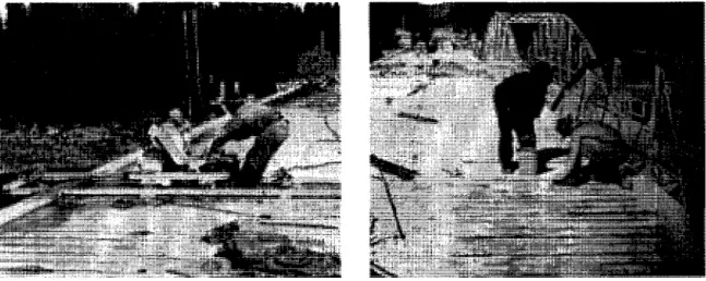
a) cutting the groove with a concrete saw. b) adding the adhesive material to the groove. Fig. 2.2. Steps of installation of NSM FRP (Sika Canada 2006) (cont. next page)
c) putting the FRP rod in the groove, d) additional adhesive is applied to fill the groove Fig. 2.3. Steps of installation of NSM FRP (Sika Canada 2006)
The process starts with sawing slots in the concrete cover, with a depth depending on the product used and the thickness of concrete cover, Fig. (2.2a).
Following the sawing process, careful cleaning of the slots is performed using high-pressurized air. Then the adhesive is applied in the slot, Fig. (2.2b). The NSMR laminates or bars are mounted in the slot Fig. (2.2c) and additional adhesive is added to fill the groove after mounting the FRP bar, Fig. (2.2d). Extra adhesive is then removed and the surface is levelled.
2.3.1. Bond behaviour
Bond is of primary importance, since it is the means for the transfer of stresses between the concrete and the FRP reinforcement developing the composite action. The bond behaviour influences the ultimate capacity of the reinforced element as well as serviceability aspects such as crack width and crack spacing. The performance of bond of NSM depends on many parameters such as groove and bar dimensions, tensile strength of concrete, type of FRP bar, type of adhesive, the FRP cross sectional shape and surface finishing, and degree of roughness of the groove surface. Few researches were made to investigate the bond performance of NSM-FRP in concrete and the factors affecting it. The most common types of bond test that can be used to investigate the bond behaviour of NSM are direct and beam pullout tests.
De Lorenzis et al. (2002) performed a direct pull-out test to investigate the mechanics of bond between NSM FRP bars and concrete using 36 C-shaped concrete specimens. The
specimen has a pre-formed square groove in the middle to have a smooth groove surface for embedment of the NSM-FRP bar as shown in Fig. 2.4. The test variables were; groove-filling material (epoxy and cement adhesives), bonded length (equal to 4, 12 and 24 times the FRP bar diameter), square groove size (equal to 1.25, 1.50, 2.00 and 2.50 times the FRP bar diameter), and surface texture of the FRP bar (spirally wound sand-coated and ribbed-deformed).
I , Dimensions in mm
H, 300
B, -300
Fig. 2.4. Test specimen, (De Lorenzis et al. 2002)
The specimens had an average concrete compressive strength of 22 MPa, the epoxy had a tensile strength of 28 MPa and the cement mortar had a tensile strength of 6.3 MPa. The ribbed-deformed GFRP bars had 873 MPa tensile strength and 37.17 GPa Young's modulus, the ribbed CFRP bars had 2014 MPa tensile strength and 109.27 GPa Young's
FIA \ L
if-11
AX —JL yi
ih-F/4
1
J^-J + ! Id, d, L Jmodulus, and the spirally wound CFRP bars had 2214 MPa tensile strength and 174 GPa Young's modulus.
Different failure modes were observed depending on the test variables: slipping at the interface between concrete and groove-filling material, splitting of the cover with no concrete cracking, slipping at the bar-cement interface, and cracking of the concrete surrounding the groove accompanied by formation of splitting cracks in the epoxy cover. For specimens with epoxy resin as groove-filling material, failure at the epoxy-concrete interface was the critical mode of failure in all cases. This was due to the smooth surface of the pre-formed grooves. While for specimens with cement-filled grooves, splitting of the cover was more frequent. The ultimate load of the specimens with cement-filled grooves was much lower than that of epoxy-filled specimens based on an average and considering the same variables, the difference was approximately 70%. This was due to the lower strength of the cement compared to epoxy (the cement mortar had a tensile strength of 6.3 MPa vs. 28 MPa tensile strength of the epoxy),which control the splitting and slip loads, respectively, as well as the adhesion between mortar and concrete. Another factor that might have influenced results is the expansion of the cement mortar. After hardening, it was noted that equally spaced transverse cracks had developed in the mortar along the bonded length of the FRP bar. These cracks were wider and more numerous for specimens with bigger grooves. The presence of such cracks might have been of negative influence on the test results, and could explain why, in some cases, mortar-filled specimens with bigger groove sizes had lower ultimate loads than those with smaller grooves.
For a given depth of the groove, the ultimate load increases as the bonded length increases. However, the average bond strength decreases, due to the non-uniform distribution of the bond stresses along the bonded length where the average bond strength depends on the failure mode. When failure is at the epoxy-concrete interface, the average bond strength, xaviu is significance at the failed interface which is computed as
where Pmax is the ultimate load, dg is the square groove size and It, is the bonded length. In
this case, the average bond strength decreases as the groove size increases, due to the non-uniform distribution of the bond stresses along the perimeter of the groove.
For the other failure mechanisms, the average bond strength, TaV2U is that at the interface
between the bar and groove-filling material, which is computed as,
where db is the bar diameter. This average bond strength increases for increased groove
size, as the bigger cover depth delays the occurrence of splitting.
De Lorenzis and Nanni (2002) performed other beam pull-out tests on NSM-CFRP and GFRP ribbed bars, to study the effect of varying the bonded length and the groove size on bond strength. The specimens were 22 unreinforced inverted T-shaped cross section concrete beams with spans of 1067 mm, depth of 254 mm and width of 254/152 mm. The beams were loaded under four point bending with a shear span of 483 mm as shown in Fig. 2.5. The specimen had a steel hinge at the top and a saw cut at the bottom, both at midspan to control the internal force distribution.
The concrete had a compressive strength of 28.2 MPa and the used epoxy had a tensile strength of 13.8 MPa. Tensile strength and modulus of elasticity of the used CFRP deformed bars, No. 3, were 1875 MPa and 104.8 GPa, respectively. For the GFRP No. 4 bars, a tensile strength of 799 MPa and a Young's modulus of 41.3 GPa were obtained. Properties of the CFRP No. 3 sandblasted bars were 1550 MPa tensile strength and 164.7 GPa Young' s modulus.
Four different bonded lengths were selected; equal to 6, 12, 18 and 24 times the diameter of the FRP bar. Four different square groove sizes equal to 1.25, 1.5, 2.0 and 2.5 times the diameter of the FRP bar were tested.
Two FRP bar diameters, 9.5 mm and 12.7 mm, were examined. Both CFRP and GFRP bars were used. For the CFRP bars, two different surface conditions, deformed and sandblasted, were examined.
Three different modes of failure were observed in this investigation depending on the testing parameters used. For specimens with the smallest groove size (1.25 times the bar diameter) splitting of the epoxy cover was observed for all the bonded length used. While by increasing the groove size, the mode of failure was changed to cracking of concrete surrounding the groove. For specimens with sandblasted CFRP bar the main mode of failure was pullout of the FRP bar.
Fig. 2.5. Tested specimens, (De Lorenzis and Nanni 2002)
The strain in the rod was monitored by using strain gauges to plot strain distribution versus location along the bonded length for different values of load as shown in Fig. 2.6. It was found that the strain distribution along the bonded length, highly non-linear at moderate load levels, tends to linear as the applied load increases as shown in Fig. 2.6. This means as the applied load increases, the bond stresses become more evenly distributed along the bonded length.
Fig. 2.6. Strain distribution along the CFRP bonded length, (De Lorenzis and Nanni 2002)
Lorenzis and Nanni (2002) used the data obtained from the strain gauges to obtain the local bond stress-slip relationship of NSM-CFRP deformed bar. It is important to define the local bond-slip that completely characterizes the bond behaviour of the system and can be used to evaluate the development length of a given type of FRP bar for each different groove size. The bond stress, x versus location diagram at a given load level is shown in Fig. 2.8. This diagram can be obtained using equation (2.3) from the first derivative of the strain versus location diagram at that load level multiplied by the elastic modulus Eb and the diameter of the FRP bar
r ( x ) - i j 5 , ^ 0 ( 2.3 )
4 ax
Where x is the coordinate along the longitudinal axis of the FRP bar within the bonded length. The definition of slip is given by:
s, (x) = s, (0) + jeb (x)dx (2.4)
0
2 4
Location (In.)
Fig. 2.7. Slip distribution along the CFRP bonded length, (De Lorenzis and Nanni 2002)
2 3 4
Location (in.)
Fig. 2.8. Bond stress distribution along the CFRP bonded length, (De Lorenzis and Nanni 2002)
The local bond-slip relationship can be obtained by combining the two curves x(x) and si(x), (Fig. 2.7 and Fig. 2.8 given from equation (2.3) and (2.4)). T versus x curve and s/ versus x curve can be obtained for each value of the applied load. Therefore, x versus slip diagram corresponding to each value of applied load can be drawn at a given load level as shown in Fig. 2.9.
• Experimental
Best Fitting of Exp.
15 20 Slip (mil In.)
33
Fig. 2.9. Local bond slip along the CFRP bonded length, (De Lorenzis and Nanni 2002)
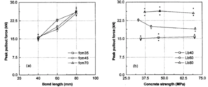
Cruz et al. (2004) investigated the bond behaviour of CFRP strip to concrete utilizing a pullout-beam test with specimens composed of two concrete specimens, specimen A and specimen B, as shown in Fig. 2.10. They used varying bonded length (40, 60 and 80 mm) and varying concrete compressive strength (35, 45, 70 MPa) with a fixed groove dimension, 15 mm depth and 3.3 mm width. Young's modulus of the CFRP strips was
158.3±2.6 GPa, 2,739.5±85.7 MPa tensile strength and the epoxy had a tensile strength of 25.8±2.1 MPa. F/2 F/2 Epoxy adhesive - , CFRP
I-
7 5 ^ 3 0 0 -(Bonded length) ^ 5 0 ^ (Bonded length) -300 •Jf-75-JfFig. 2.10. Specimen of pullout-bending test, (Cruz et al. 2004)
The mode of failure for all the specimens was an interface failure or debonding failure between the epoxy and the concrete or between the CFRP strip and the epoxy. It was found from the experimental results that the pullout force was increased with the bond length, Lb as shown in Fig. 2.11. Also, the influence of the concrete compressive strength was marginal as the mode of failure was debonding failure and no cracks were observed in the concrete in this kind of test, as shown in Fig. 2.12. It was also found that the bond stress, Tmax decreases with bond length and is practically insensitive to concrete strength.
30.0 30.0 22.5 o Z 15.0
I»
(b) Lb40 Lb60 Lb80 20 40 60 80 Bond length (mm) 0.0 25.0 37.5 50.0 62.5Concrete strength (MPa)
75.0
Fig. 2.11. Influence of bond length on the Fig. 2.12. Influence of concrete strength oi peak pullout force, (Cruz et al. 2004) the peak pullout force, (Cruz et al. 2004)
2.3.2. Flexural strengthening
One of the benefits of strengthening a structure is increasing its flexural strength. NSMR plays a great role in flexural strengthening. A lot of research was done on increasing the flexural capacity of concrete beams with FRP-NSMR. A large number of parameters can affect the flexural strengthening with FRP-NSMR.
Some research was done with bars and others with strips and a comparison was made between them. A summary of the exciting work will be summarized in the following section.
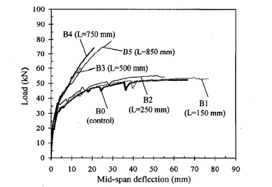
Hassan and Rizkalla (2003) conducted a flexural investigation on concrete beams strengthened with NSM CFRP strips using nine concrete T-section beams with a span of 2500 mm and a depth of 300 mm as shown in Fig. 2.13. Hassan and Rizkalla (2003) terminated the steel reinforcement in the middle to control the debonding failure and to locate it in the middle of the beam. One of their main objectives was to evaluate the minimum bonded length required to develop the ultimate force of the strip to provide sufficient increase in the flexural capacity. Eight different bonded lengths of 150, 250, 500, 750, 850, 950, 1050, and 1200 mm were used. The CFRP strips, which were produced by S&P Clever Reinforcement Company, Switzerland, have a width of 25 mm and a total thickness of 1.2 mm. The strips have a modulus of elasticity of 150 GPa and an ultimate tensile strength of 2,000 MPa as reported by the manufacturer. En-Force CFL epoxy adhesive was used for bonding the strips to the concrete.
It was clear from the results that using embedment lengths less than 250 mm provides insignificant improvement in strength as shown in Fig. 2.14. This is due to the early debonding of the CFRP strips. A small increase in strength (3.8%) was observed for embedment lengths greater than 250 mm. Specimens with embedment lengths of 500 and 750 mm provide an increase of about 15.4% and 42.3%, respectively; they failed due to debonding of the CFRP strips. Debonding was at both ends of the strips as well as at midspan. This was due to shear stress concentration at the cut-off points as well as at the flexural cracks at the midspan.
shown in Fig. 2.15. They concluded that the minimum embedment length needed to rupture the near surface mounted CFRP strips, with the given dimensions used in this program is 850 mm. This means that for small embedment lengths less than 250 mm, debonding of the adhesive from the surrounding concrete occurred before yielding of the internal steel reinforcement.
750 300 750 2700 mm 1250 1250
LJJ
LOAD CFRP stripn
L/3 L/3 1111 i _ PI gauges Concrete • Strain gauges blockLVDT
i P-50
' . • - . ' • • 750
750
Slip monitoring
"3
o -J 100 90 80 70 60 50 40 30 20 10 0 0 10 20 30 40 50 60 70 80 90 Mid-span deflection (mm)Fig. 2.14. Load-deflection behaviour of test specimens with embedded length (150-850 mm), (Hassan and Rizkalla 2003)
_; B4(L=750mm)
.; y / ~ ~ —
B 5(
L = 8 5°
m m)
^ - " B 3 (D=500 mm)'kf^
\
B2 - \ M T B 0 ( L = 2 5 0 m m ) M ( c o n t r o l ) - 1 — ' — I — ' — I — ' — 1 — ' — 1 — ' — 1 — ' — i — (L= _1 Bl =150 mm) I — ' — 1 — ' — 20 30 40 50 60 70 Mid-span deflection (mm) 90Fig. 2.15. Load-deflection behaviour of test specimens with embedded length (950-1200 mm), (Hassan and Rizkalla 2003)
Hassan and Rizkalla (2004) conducted another investigation using CFRP bars instead of the CFRP strips using the same dimensions and setup of the beams as in the previous investigation, (Fig. 2.13). The authors used two different kinds of epoxy adhesive with tensile strength and modulus of elasticity of 48 MPa and 1200 MPa, respectively, for the first adhesive. While the second type has a tensile strength and modulus of elasticity of 62 MPa and 3000 MPa, respectively to compare the effect of changing the adhesive tensile strength on the performance.
They used four different bonded lengths, 150, 550, 800 and 1200 mm. Beams with the smallest bonded length, 150 mm provided insignificant increase in the strength due to early debonding of the CFRP bar. Beams with 550, 800 and 1200 mm embedded length providing 19.6, 30.4 and 41.1 % increase in the ultimate capacity, respectively. Using two different kinds of adhesives had a negligible effect on the ultimate load as the mode of failure for all beams was debonding at midspan in the place where the internal steel reinforcement was terminated. The maximum measured tensile strain for the CFRP bars at failure was about 40% to 45% of the rupture strain of the bar.
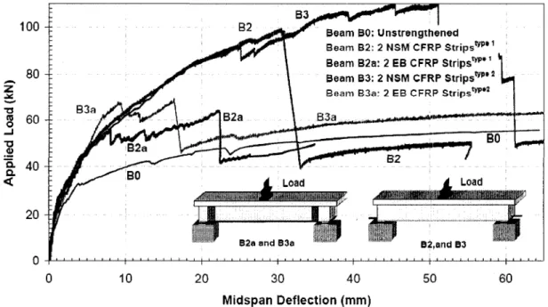
El-Hacha and Rizkalla (2004) examined the structural performance of reinforced concrete beams strengthened in flexure with various NSM-FRP reinforcements compared to beams strengthened with externally-bonded FRP reinforcement. Eight simply supported concrete T-beams were constructed with a span of 2700 mm, a depth of 300 mm and a width of 150 mm. The beams were tested under a monotonically increasing concentrated load applied at mid-span. One beam was tested without strengthening as a control beam for comparison purposes, four beams were strengthened with different NSM-FRP systems, one CFRP bar, two types of CFRP strips, and a GFRP strip. Three beams were strengthened with externally bonded CFRP and GFRP strips as shown in Fig. 2.16. Table 2.3 summarises the test parameters for the tested beams.
C—~1
C
18x30 •I 7 5 6.4x19•I75K-EI
6.4x25 aaaaaaaaau mmm^m -H75l*-6.4x25 k-38 U-wrap J./CFRP \ J sheet 323
25 One9.5NSM Two 2x16 NSM Two 1.2x25 NSM Five 2x20 NSM Externally Bonded Five 2x20 ExternallyCFRPrebar CFRP strips type 1 CFRP strips type 2 GFRP strips CFRP strips: Bonded GFRP strips Two 2x16 type 1
Two 1.2x25 type 2
Fig. 2.16. FRP strengthening schemes, (El-Hacha and Rizkalla 2004)
Table 2.3. Test matrix for test specimens (El-Hacha and Rizkala 2004) Beam No. B0 Bl B2 B3 B4 B2a B3a B4a FRP Strengthening System No strengthening
One 9.5 mm NSM CFRP bar (a)
Two 2 mm* 16 mm NSM CFRP strips type 1(a)
Two 1.2mmx25 mm NSM CFRP strips type 2(b) Five 2 mmx20 mm NSM GFRP thermoplastic strips(c)
Two 2 mm><16 mm Externally Bonded CFRP strips type 1(a) Two 2 mmxl6 mm Externally Bonded CFRP strips type 2(b) Five 2 mmx20 mm Externally Bonded GFRP Strips
(a) Hughes Brothers (b) Structural Composite (c) Dow Plastic Chemicals
The variable used in this investigation were the type of fibre (carbon or glass) and the shape of the FRP reinforcement (bars and strips), the effectiveness of the NSM-FRP bars and strips compared to the externally bonded FRP strips having the same axial stiffness. The embedded length of all the FRP-NSM bars and strips and the length of the externally bonded FRP strips were kept constant in all beams. Also the axial stiffness (EA)FRP for all FRP reinforcement was kept constant.
It was found that the flexural behaviour for all strengthened beams was similar to that of the unstrengthened beam before cracking and a nonlinear behaviour was observed up to failure as shown in Fig. 2.17. Using the same axial stiffness for the CFRP strips and bar, an increase in the ultimate strength of 69% for beam (Bl) with FRP bar and 79 %, and 99
% increase for beams with two different types of strip respectively. Using NSM-FRP reinforcement resulted in a reduction in deflection and crack widths as well delayed the formation of new cracks in the strengthened beams.
0 10 20 30 40 50 60 Midspan Deflection (mm)
Fig. 2.17. Load-deflection curve for strengthened beams with NSM CFRP strips and rebar, (El-Hacha and Rizkalla 2004)
Using the same axial stiffness, (EA)FRP, of the NSM-CFRP strips and the externally
bonded CFRP strips, the externally bonded CFRP strips increased the strength by only 16.6 % and 25 % for the beams (B2a, B3a) compared to the unstrengthened beam due to debonding failure of the externally bonded strips from the concrete surface. However, the NSM CFRP strips increased the strength by 79 and 99 % for the beams (B2, B3) as
shown in Fig. 2.18. The amount of strength increased using the same CFRP strips as NSM was about 4.8 and 4.0 times that obtained using externally bonded strips as shown in Fig. 2.18. Thus, the NSM strengthening technique using CFRP strips is more effective in comparison to externally bonded one.
The beam strengthened with GFRP strips as NSM reinforcement, exhibited significant enhancement in strength and stiffness in comparison to the unstrengthened beam. An increase in the ultimate strength of 85% was observed while the ultimate load carrying
capacity of the beam strengthened using externally bonded GFRP strips increased by 28 % as shown in Fig. 2.19.
Fig. 2.18. Load-deflection curve for strengthened beams with NSM and externally bonded CFRP strips, (El-Hacha and Rizkalla 2004)
Fig. 2.19. Load-deflection curve for strengthened beams with NSM CFRP and GFRP strips, (El-Hacha and Rizkalla 2004)