OATAO is an open access repository that collects the work of Toulouse
researchers and makes it freely available over the web where possible
Any correspondence concerning this service should be sent
to the repository administrator:
[email protected]
This is an author’s version published in:
https://oatao.univ-toulouse.fr/2
6959
To cite this version:
Martin, Baptiste and Dantras, Eric and Lonjon, Antoine and Lacabanne, Colette and Laffont, Lydia Magnetoelectric coupling in PVDF/Nano
NaNbO3/NanoNi composites: Influence of Ni particles aspect ratio. (2020) IEEE Transactions on Dielectrics and Electrical Insulation, 27 (5). 1381-1386. ISSN 1070-9878 .
Official URL:
https://doi.org/10.1109/TDEI.2020.008432
Magnetoelectric Coupling in PVDF/Nano NaNbO
3
/NanoNi
Composites: Influence of Ni Particles Aspect Ratio
Baptiste Martin, Eric Dantras, Antoine Lonjon
andColette Lacabanne
CIRIMAT, Physique des Polymères, Université de Toulouse118 route de Narbonne 31062 Toulouse cedex 09, France
Lydia Laffont
CIRIMAT, ENSIACET, Université de Toulouse 4 allée Emile Monso
31030 Toulouse, France
ABSTRACT
In this work, three phase magnetoelectric nanocomposites are successfully prepared by solvent casting from α-PVDF. The extrinsic piezoelectric effect is insured by 20 vol% of NaNbO3 ferroelectric nanoparticles prepared by the hydrothermal process. Nickel is
chosen as the magnetic phase. In order to maintain insulation, electrical percolation is avoided by using nickel contents lower than the percolation threshold. Two different morphologies are employed: spherical nanoparticles (NiNPs) and nanochains (NNCs) with an aspect ratio of 80. NNCs are obtained by a polyol process under a magnetic field. Thin films of nanocomposites are processed by hot pressing. The real part of the dielectric permittivity (’) of composites is governed by Maxwell-Wagner-Sillars
polarization at the PVDF/Ni interfaces. An important increase of ’ at low frequency is
observed for PVDF/NaNbO3/NNCs composites; it favors the magnetoelectric coupling.
Piezoelectric properties of composites are dependent upon mechanical modulus so that the most higher d33 is obtained for PVDF / NaNbO3 / NiNPs. Magnetoelectric coupling
coefficient (ME) is determined from magnetoelectric intensity. PVDF / NaNbO3 / NiNPs
composites exhibit enhanced magnetoelectric coupling. The ME coupling coefficient
reaches 4.2V/(mOe). The magnetic properties are significantly improved by the NiNPs
Index Terms — magnetoelectric properties, PVDF / NaNbO3 / Ni composite,
piezoelectric coefficient, dielectric permittivity, magnetization, aspect ratio
1 INTRODUCTION
DURING the last 20 years, many works were carried out on inorganic magnetoelectric (ME) composites [1] that allow to reach strong ME coupling at ambient temperature. Two approaches were developed: laminated structures [2] and dispersed composites [3]. Laminated composites were widely studied because they exhibit the best ME coupling. Dispersed composites [4–6] also exhibit interesting magnetoelectric coupling. Despite important ME response, these inorganic materials exhibit several drawbacks as they are often brittle, and hard to process.
In the opposite, polymeric materials are easily processed and resilient. Accordingly, composites with piezoelectric polymeric matrix were realized and ME polymer-based composites were developed. Several matrices were used: polyurethane [7], but mostly -PVDF[8] and PVDF-TrFE[9].
Most of these works investigated the influence of the particles nature over the magnetic properties. Thus, several ferrites [10– 12] as well as magnetic metals [13] were used. These composites were widely studied and led to applications like magnetic field sensors [14] memories [15] or microwave tunable devices [16]. Despite interesting ME properties, intrinsic piezoelectric PVDF based composites have a huge limitation in temperature since above 90°C, the matrix becomes paraelectric. The other drawback of these two-phase composites is the high electric field needed to get polarization. Alternatively, three-phase composites were also proposed, at first by Nan et al[17] by dispersion of terfenol-D and PZT in a -PVDF matrix. The magnetoelectric coupling was strongly dependent on composition. First, it is mandatory that the composite remains insulating in order to allow its polarization. The introduction of metallic magnetic particles in polymers above the percolation threshold might allow the building of a conductive path responsible for the percolation phenomena. Then, the composite becomes conductive. To avoid
percolation, the content in conductive particles must be lower than the percolation threshold.
This study explores an original way to realize a three-phase ME composite based on α-PVDF. Nickel particles were selected for their good magnetic properties and their ability to reach high aspect ratio with enhanced magnetic properties but with a low fraction in order to keep the electrical conduction as low as possible. Sodium niobate (NaNbO3) was chosen
since it allows us to realize a lead free extrinsic piezoelectric phase with a high Curie temperature. Note that such inorganic piezoelectric ceramics allow mild poling conditions. We present here the route to process composites; then, the influence of the magnetic particles aspect ratio on the ME effect of composites was analysed.
2 EXPERIMENTAL
2.1 MATERIALS
Polyvinylidenefluoride (PVDF) was chosen as a matrix due to its easy processing and good resilience. PVDF in the α phase was provided by Arkema as micronized powder under the trade mark Kynar 500.
Nb2O5 and sodium hydroxide were provided by
Sigma-Aldrich. Nb2O5 was dissolved in concentrated NaOH (aq) and
introduced in an autoclave; cubic particles were obtained [18]. NaNbO3 particles were washed in water and dispersed by
sonication in acetone (Figure 1a). NaNbO3 has been chosen
for its lead-free composition and low poling field.
Two types of magnetic particles were employed for this study. Commercial Ni spherical particles (NiNPs), provided by Sigma, present an irregular and pseudo spherical aspect with a mean size of 2 µm (Figure 1b).
Figure 1. SEM images of a) NaNbO3 particles; b) Ni spherical particles
NiNPs; c) and d) Ni high aspect ratio nanochains NNCs.
High aspect ratio particles were synthetized in the laboratory. High aspect ratio was obtained by polyol reduction of Ni(CH3COO)24H2O in 1,2 butanediol under 10mT DC
magnetic field. These pseudo spherical particles were assembled under the influence of a magnetic field in order to form nickel nanochains (NNC). More details were given in a previous publication [19].
Particles’ morphology was characterized by SEM and micrographs are shown in Figure 1. NaNbO3 particles appear
to be cubic with a mean size of 1µm (Figure 1a).
NNCs present regular length and diameter (Figures 1c and 1d). Statistical analysis was provided in a previous work [19]. Mean aspect ratio 𝜉 Equation (1) is about 80.
𝜉 𝑙𝑒𝑛𝑔𝑡ℎ
𝑑𝑖𝑎𝑚𝑒𝑡𝑒𝑟
(1)
2.2 COMPOSITES PREPARATION
Typical protocol for the composite processing is the following: PVDF powder was dissolved in acetone while nickel and NaNbO3 particles were also dispersed in acetone in a separated
content. Particles suspensions were sonicated to avoid aggregation. The mixture of dissolved matrix, NaNbO3 and Ni
suspensions were mixed together and submitted to ultrasonic agitation for 2 minutes in order to produce a homogeneous mixture. The mixture was then quickly precipitated to obtain the composite.
The precipitate composite was then hot-pressed under 1 MPa at 220°C in order to get films with a thickness of around 200µm.
The NaNbO3 content was fixed at 20 vol% for all samples.
In order to study the influence of nickel proportion, composites were proceed with 0.3 and 2 vol% of nickel.
2.3 POLING PROTOCOL
Getting macroscopic piezoelectricity in composites requires a poling step. An unidirectional DC electric field was applied to the sample placed in castor oil in order to avoid breakdown. The DC field of 5 kV/mm was maintained for 30 minutes.
The d33 piezoelectric coefficient measurements were carried
out 24 h after the polarization step in order to allow elimination of electric charges accumulated on the composite’s surface.
2.4 SCANNING ELECTRON MICROSCOPY
Scanning electron microscopy (SEM) was performed on particles to examine their morphology on a JEOL 7800 Prime. Images were also made on composites to check the dispersion of particles. Observations were performed under secondary electrons on an aluminium surface.
2.5 DYNAMIC DIELECTRIC SPECTROSCOPY
Dielectric permittivity was measured on composite films thanks to the Novocontrol broadband dielectric spectrometer (BDS). Measurements were performed as a function of frequency between 1×10⁻²Hz and 1×10⁶Hz. Isotherms are
2.6 PIEZOELECTRIC MEASUREMENTS
The piezoelectric coefficient was measured by a PM 200 piezometer supplied by Piezotest UK.
Frequency and stress were set at 110 Hz and 0.25 N, respectively. The stress was applied to the sample in the same direction as the poling field; the polarization was measured in order to get the d33 coefficient.
2.7 MAGNETIC PROPERTIES MEASUREMENTS
Magnetization was measured thanks to SQUID magnetometer. Hysteresis loops were recorded between -5 and 5 T in order to reach saturation. These measurements were carried out on raw NiNPs, NNCs and PVDF / nickel composite in order to determine the influence of the processing method over the NNCs orientation.
2.8 MAGNETOELECTRIC MEASUREMENTS
ME properties were measured as a function of AC magnetic field (HAC) and DC magnetic field (HDC). Samples were thin
film shaped with a thickness of 200µm. Their surfaces were metalized to avoid contact resistivity.
3 RESULTS AND DISCUSSION
3.1 ELECTRICAL PROPERTIES
Real part of dielectric permittivity (ε’) is plotted as a function of frequency at 300K (Figure 2). Experiments were carried out on the two types of composites i.e with NiNPs and NNCs. For PVDF / NiNPs composites and PVDF / NNCs composites at 0.3 vol%, permittivity values are close from each other in the whole frequency range. For the 2 vol% PVDF / NNCs composite, a significant increase of ’ is observed below 1 Hz. This increase is characteristic of the proximity of the percolation threshold and caused by the Maxwell-Wagner-Sillars (MWS) polarisation. This polarisation is due to charge accumulation at the interfaces.
Figure 2.Dielectric permittivity versus frequency at ambient temperature for PVDF / NaNbO3 / Ni composites.
Many studies [20] have reported the increase of permittivity towards lower frequencies upon the introduction of conductive
particles in polymeric matrices. Electrical percolation corresponding to the insulator / conductor transition is responsible for this evolution. Then, the electrical conductivity (𝜎 ) is described by the Stauffer law [21],
𝜎
𝜎 𝑝
𝑝
(2)
where 0 is the theoretical conductivity of 100% NNCs, p is
the volume fraction, pC is the volume fraction at the
percolation threshold and t is the critical exponent.
We showed in a previous work that pC = 2.3 vol% for
PVDF / NNCs[19]. The proximity of the percolation threshold explains why ’ reaches such a high value. Moreover, it has been shown that pC strongly depends on the aspect ratio of
particles [22]. Thus, for spherical particles, pC is much higher
than2 vol%.
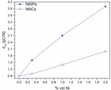
3.2 PIEZOELECTRIC PROPERTIES
Electro-mechanical coupling is characterized by the d33
coefficient. The influence of Ni particles morphology is presented on Figure 3 where d33 is plotted as a function of Ni
volume content.
Figure 3. Piezoelectric coefficient d33 (pC/N) in PVDF / NaNbO3 20 vol % /
Ni particles versus volume content in Ni.
Composites were poled under the same macroscopic field i.e. 5 kV/mm. Despite the proximity of the percolation threshold, NNCs composites were successfully poled.
It is important to note that all three-phase composites exhibit a higher piezoelectric coefficient than the two-phase composites without conducting particles. It has already been shown that adding conductive particles in a piezoelectric composite leads to a higher d33[23].
Differences recorded between composites with NiNPs and NNCs respectively have been associated with the variation induced on the mechanical storage modulus that increases with the aspect ratio of particles [24]. It explains the decrease on d33 upon increasing of the aspect ratio.
3.2 MAGNETIC PROPERTIES
Magnetic properties of NiNPs, NNCs, PVDF / NiNPs and PVDF / NNCs have been determined in order to underline the
influence of morphology over the magnetic behaviour. We have reported in Table 1 remnant magnetization in the parallel direction (Mr//) and remnant magnetization in the
perpendicular direction (Mr), coercive field in the parallel
direction (HC//) and coercive field in the perpendicular
direction (HC).
Table 1. Magnetic properties of NPS; NNCs, PVDF / NiNPs and PVDF /
NNCs composites. Sample Mr// (emu/g) Mr (emu/g) Mr / MS Hc // (Oe) Hc (Oe) NiNPs 3.81 3.81 18 148 148 NNCs 10.80 10.80 20 163 163 PVDF/NiNPs 0.24 0.24 5.03 89 89 PVDF/NNCs 0.41 0.14 4.3 210 180
Spherical particles show an isotropic magnetization, as expected. Mr// and Mr reach the value of 3.81 emu/g and a ratio Mr / Ms of 18%. As for the magnetization, coercive field (HC), has the same value of 148 Oe in the transverse and in the
longitudinal direction.
Figure 4 represents the magnetization of composites as magnetic hysteresis loops. We notice that despite a low content of Ni (2 vol%), composites present a ferromagnetic behaviour. As for the NiNPs, PVDF / NiNPs composite shows isotropic properties. The good dispersion and the isotropic properties of particles lead to an isotropic magnetic composite.
Figure 4. Magnetization versus field hysteresis loop for PVDF / Ni composites in perpendicular and parallel direction at 300K.
When NNCs are introduced in a composite, anisotropy appears clearly. In the parallel direction, Mr (PVDF / NNCs)
becomes almost twice as high as PVDF / NiNPs. In the perpendicular direction, Mr (PVDF / NNCs) is almost twice
lower than for PVDF / NiNPs. This anisotropy reflects the morphology of Ni particles but also their orientation due to the
composite processing. HC exhibits different values in the
longitudinal and in the transverse direction of the composite (Figure 5). It is interesting to note that, in the parallel direction HC is also analogous for PVDF / NNCs and PVDF / NiNPs.
Figure 5.Zoom on the hysteresis loop between -25 and 25mT for PVDF / Ni composites in the perpendicular and parallel direction at 300K.
3.4 MAGNETOELECTRIC COUPLING MEASUREMENTS
Magnetoelectric response of PVDF / NaNbO3 / Ni
composites was registered in the intensity mode (IME), on a
homemade set-up.
Composites were metalized with silver paint in order to minimize the contact resistivity between sample and probe. Intensity was measured thanks to a lock-in amplifier in order to extract signal from noise. Samples were placed in the middle of the coil where a homogenous and unidirectional field prevailed.
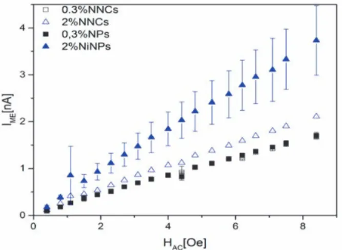
Figure 6 shows IME as a function of AC field intensity (HAC)
at 1 kHz under a DC field of 4000 Oe. IME values exhibit a
linear increase with HAC regardless from the nickel particles
content or morphology. For 0.3 vol % Ni, IME has practically
the same value for NiNPs or NNCs. The slope is also similar for both. In NiNPs composites, d33 was found to be higher
than in NNCs composites. Nevertheless, it has been shown that NNCs exhibit enhanced magnetic properties. In these composites with low nickel content, magnetic properties are preeminent for the magnetoelectric coupling.
For 2 vol% nickel composites, magnetic effects are more important. IME is higher for both morphologies than for 0.3
vol% composites. IME becomes much higher for NiNPs
composite than for the NNCs one. The slope is also increased. These strong differences can be explained by the important evolution of d33. As shown in Figure 3, d33 is twice as high as
in NiNPs composite, which plays an important role over the coupling. Here, magnetic properties enhancement induces by the aspect ratio of NNCs is not strong enough to set IME off.
Two causes appear to explain this phenomenon. Firstly, the d33
is much more important than previously, more than double for NiNPs when it was only 30% higher in 0.3 vol% Ni composites. The other reason is the proximity of percolation
threshold in the 2 vol% NNCs composite. As shown in Figure 2, permittivity rises strongly inducing more dielectric losses.
Figure 6. Magnetoelectric intensity for PVDF/NaNbO3/Ni composites.
In order to compare our data with literature, the ME
magnetoelectric coefficient of polarisation has been calculated thanks to Equation (3):
𝛼
𝐼
𝑆𝜔ℎ
(3)
where IME the ME response of material, S is the surface of the
sample, is the angular frequency and hAC is the intensity of
the ac magnetic field.
Then, we obtain the magneto electric coupling coefficient 𝛼 from Equation (4):
𝛼
𝛼
𝜀𝜀
(4)
where is the relative dielectric permittivity of the sample and 0 the vacuum dielectric permittivity.
The ME values give us a more precise understanding of the
phenomenon. The histogram of Figure 7 reports the coupling coefficient for the studied composites.
Figure 7. Magnetoelectric coupling coefficient 𝛂𝐌𝐄 for PVDF / NaNbO3 / Ni
composites.
First, let us consider PVDF / NNCs composites. We observe that for 0.3 vol% Ni, PVDF / NNCs exhibit a higher value of ME than PVDF / NiNPs. Based on the previous
experiences, it confirms that the enhancement of magnetic properties plays an important role while the permittivity of composite remains close and d33 does not change in a drastic
manner. For the 2 vol% NNCs composite, we observe a decrease of d33. Despite the slightly higher IME, ’ increases
due to the proximity of the percolation threshold. Consequently, ME decreases as predicted by Equation 4.
Second, let us discuss data on PVDF / NiNPs composites. ME rises from 2.8 V/(mOe) for 0.3vol% Ni to 4.2 V/(mOe)
for 2 vol% Ni. As show by Figure 6, IME increases strongly
with NiNPs. This increase reflects the increase of d33 by a
factor 2 in this composite. Since the percolation threshold is far away from 2 vol% for spherical particles [20], the evolution of the piezoelectric transduction governs the magnetoelectric coupling for PVDF / NiNPs.
4 CONCLUSIONS
Three-phase polymer based composites PVDF / NaNbO3 /
Ni have been elaborated in order to reach satisfactory magnetoelectric coupling; extrinsic piezoelectric effect is insured by 20 vol% of NaNbO3 particles (1 µm) and magnetic
properties are due to Ni particles with different aspect ratios. Ni quasi-spherical particles (2 µm) NiNPs have been compared to Ni nano chains (NNCs) obtained by a polyol reduction method under a magnetic field leading to particles with a mean aspect ratio of 80. Two contents of nickel 0.3 and 2 vol% have been used. Dielectric permittivity exhibits an important increase for the 2 vol% NNCs composite due to its proximity with the electrical percolation threshold. Electro-mechanical coupling has shown that adding Ni in the composite increases the piezoelectric response. This effect is more important in PVDF / NaNbO3 / NiNPs composite, which
give a d33 of 4.1 pC/N, i.e. four times higher than in PVDF /
NaNbO3 composite. Magnetic measurements confirm the
ferromagnetic behavior of the composites despite the low amount of Ni. It also shows that NNCs allow an enhancement of magnetic properties such as Mr and HC. Magnetoelectric
measurements prove the existence of the ME coupling by producing a ME signal as a function of HAC. It shows that for
low amount of nickel, NNCs allow better coupling while when the permittivity increases, it is more interesting to use Ni NPs. Magnetoelectric properties of PVDF / NaNbO3 / Ni
composites open the possibility of new applications in the field of smart materials. Thanks to NaNbO3’s high TC, we
might propose magnetoelectric composites with a non-electroactive matrix such as high performance thermoplastic. These materials would allow us to envision the processing of high temperature sensors.
REFERENCES
[1] C.-W. Nan et al, “Multiferroic magnetoelectric composites: Historical perspective, status, and future directions,” J. Appl. Phys., vol. 103, no. 3, p. 031101, Feb 2008.
[2] N. Cai et al, “Dielectric, ferroelectric, magnetic, and magnetoelectric properties of multiferroic laminated composites,” Phys. Rev. B, vol. 68, no. 22, Dec 2003.
[3] J. Y. Zhai et al, “Dielectric behavior and magnetoelectric properties of lead zirconate titanate/Co-ferrite particulate composites,” Materials Science and Engineering: B, vol. 99, no. 1–3, pp. 329–331, May 2003. [4] M. Etier et al, “Magnetoelectric coupling on multiferroic cobalt ferrite–
barium titanate ceramic composites with different connectivity schemes,” Acta Materialia, vol. 90, pp. 1–9, May 2015.
[5] M. Naveed-Ul-Haq et al, “Strong converse magnetoelectric effect in (Ba,Ca)(Zr,Ti)O3 - NiFe2O4 multiferroics: A relationship between phase-connectivity and interface coupling,” Acta Materialia, vol. 144, pp. 305–313, Feb 2018.
[6] D. Huang, C. Lu, and H. Bing, “Self-biased magnetoelectric coupling characteristics of three-phase composite transducers with nanocrystallin soft magnetic alloy,” Appl. Phys. A, vol. 120, no. 1, pp. 115–120, Jul 2015.
[7] D. Guyomar et al, “Magnetoelectricity in polyurethane films loaded with different magnetic particles,” Materials Let., vol. 63, no. 6–7, pp. 611– 613, Mar 2009.
[8] P. Martins, C. M. Costa, and S. Lanceros-Mendez, “Nucleation of electroactive β-phase poly(vinilidene fluoride) with CoFe2O4 and NiFe2O4 nanofillers: a new method for the preparation of multiferroic nanocomposites,” Appl. Phys. A, vol. 103, no. 1, pp. 233–237, Apr. 2011.
[9] P. Martins et al, “Linear anhysteretic direct magnetoelectric effect in Ni0.5Zn0.5Fe2O4/poly(vinylidene fluoride-trifluoroethylene) 0-3 nano-
composites,” J. Phys. D: Appl. Phys., vol. 44, no. 48, p. 482001, Dec. 2011.
[10] P. Martins et al, “Tailored Magnetic and Magnetoelectric Responses of Polymer-Based Composites,” ACS Applied Materials & Interfaces, vol. 7, no. 27, pp. 15017–15022, Jul. 2015
[11] P. Martins et al, “Wide-Range Magnetoelectric Response on Hybrid Polymer Composites Based on Filler Type and Content,” Polymers, vol. 9, no. 12, p. 62, Feb 2017.
[12] R. Belouadah et al, “Magnetoelectric coupling in Fe 3 O 4 /P(VDF-TrFE) nanocomposites,” Sensors and Actuators A: Physical, vol. 247, pp. 298–306, Aug 2016.
[13] T. H. L. Nguyen et al, “Magnetoelectric properties of nickel nanowires-P(VDF–TrFE) composites,” Mat. Chem. Phys., vol. 153, pp. 195–201, Mar 2015.
[14] P. Martins et al, “Tailored Magnetic and Magnetoelectric Responses of Polymer-Based Composites,” ACS Appl. Mat. Interfaces, vol. 7, no. 27, pp. 15017–15022, Jul 2015.
[15] A. Ahlawat et al, “Tunable Magnetoelectric Nonvolatile Memory Devices Based on SmFeO3/P(VDF-TrFE) Nanocomposite Films,” ACS
Applied Nano Materials, vol. 1, no. 7, pp. 3196–3203, Jul 2018. [16] V. Castel, C. Brosseau, and J. Ben Youssef, “Magnetoelectricity in
Piezoelectric/Magnetostrictive Nanocomposites at Microwave Frequencies,” IEEE Trans. Mag., vol. 45, no. 10, pp. 4321–4324, Oct. 2009
[17] C.-W. Nan et al, “A three-phase magnetoelectric composite of piezoelectric ceramics, rare-earth iron alloys, and polymer,” Appl. Phys. Let., vol. 81, no. 20, pp. 3831–3833, Nov 2002.
[18] M. Alexandre et al, “Piezoelectric properties of polymer/lead-free ceramic composites,” Phase Transitions, vol. 89, no. 7–8, pp. 708–716, Aug 2016.
[19] B. Martin et al, “Fabrication of Nickel NanoChains/PVDF Nanocomposites and Their Electrical/Magnetic Properties,” Physica Status Solidi (a), vol. 0, no. 0, p. 1900158.
[20] A. Lonjon et al, “Low filled conductive P(VDF-TrFE) composites: Influence of silver particles aspect ratio on percolation threshold from spheres to nanowires,” J. Non-Crystalline Solids, vol. 358, no. 23, pp. 3074–3078, Dec 2012.
[21] D. Stauffer and A. Aharony, Introduction to Percolation Theory, vol. 9. 1994.
[22] L. Rivière et al, “Silver fillers aspect ratio influence on electrical and thermal conductivity in PEEK/Ag nanocomposites,” European Polymer J., vol. 85, pp. 115–125, Dec 2016.
[23] D. Carponcin et al., “Electrical and Piezoelectric Behavior of Polyamide/PZT/CNT Multifunctional Nanocomposites,” Advanced Engineering Materials, vol. 16, no. 8, pp. 1018–1025, 2014.
[24] A. Lonjon, P. Demont, E. Dantras, and C. Lacabanne, “Mechanical improvement of P(VDF-TrFE) /nickel nanowires conductive nanocomposites: Influence of particles aspect ratio,” Journal of Non-Crystalline Solids, vol. 358, no. 2, pp. 236–240, Jan 2012