Pépite | Modélisation du comportement cyclique des bétons : approches mésoscopiques
195
0
0
Texte intégral
(2) Thèse de Yue Sun, Université de Lille, 2019. © 2019 Tous droits réservés.. lilliad.univ-lille.fr.
(3) Thèse de Yue Sun, Université de Lille, 2019. Abstract We present in this work a Finite Element based model, which is devoted to describing failure mechanics of quasi-brittle materials and identifying the minimum necessary ingredients for the fatigue behaviors with low number of cycles. The material will be studied at meso-scale, and be considered as heterogeneous media. The model is formulated in a sound framework of the Enhanced Finite Element Method (EFEM). As internal enhancements, two kinds of discontinuities are performed. On the one hand, strong discontinuities aim to illustrate cracks and fractures. On the other hand, weak discontinuities are used to describe heterogeneities. In addition to the initiations and propagations of cracks, the closure of cracks is also taken into account. As a first step of validation, the proposed model is applied to reproduce the mechanical responses of heterogeneous material by adding the closure mechanism to the mode-I and mode-II strong discontinuity. We show the ability of the model to simulate some of the main characteristics of such materials, for instance, the emerged asymmetric traction/compression behavior, the stiffness recovery, the plastic deformation, and the hysteresis phenomenon. Further, we compare the simulation results to experimental ones. The studied concrete material is composed of a matrix of cement and aggregates. By applying the same formulations and loadings, the proposed model succeeds in reproducing the macroscopic responses for monotonic and cyclic compression tests. Finally, the model is also tested by comparing with the experimental data in triaxial loadings.. © 2019 Tous droits réservés.. lilliad.univ-lille.fr.
(4) Thèse de Yue Sun, Université de Lille, 2019. © 2019 Tous droits réservés.. lilliad.univ-lille.fr.
(5) Thèse de Yue Sun, Université de Lille, 2019. R´ esum´ e Nous pr´esentons dans ce travail un mod`ele bas´e sur les ´el´ements finis, qui est consacr´e `a la description des m´ecanismes de ruptures des mat´eriaux quasi fragiles et `a l’identification des ingr´edients minimum n´ecessaires pour les comportements `a la fatigue avec petit numbre de cycles. Le mat´eriel sera ´etudi´e `a m´eso-´echelle, et sera consid´er´e comme un milieu h´et´erog`ene. Le mod`ele est d´evelopp´e dans un cadre de la m´ethode EFEM (Enhanced Finite Element Method). En tant qu’enrichissements internes, deux types de discontinuit´es sont effectu´es. D’une part, les discontinuit´es fortes visent a` illustrer les fissures et les fractures. D’autre part, les discontinuit´es faibles sont utilis´ees pour d´ecrire les h´et´erog´en´eit´es. En plus de l’initiation et de la propagation des fissures, la recherche de la refermeture des fissures est ´egalement prise en compte. Dans une premi`ere ´etape de validation, le mod`ele propos´e est appliqu´e pour reproduire les r´eponses m´ecaniques de mat´eriaux h´et´erog`enes, en ajoutant le m´ecanisme de fermeture aux discontinuit´es fortes du mode-I et du mode-II. Nous montrons la capacit´e du mod`ele `a simuler certaines des caract´eristiques principales de ces mat´eriaux, par exemple, l’´emergence du comportement asym´etrique de traction/compression, la r´ecup´eration de rigidit´e, la d´eformation plastique, et le ph´enom`ene de l’hyst´er´esis. De plus, nous comparons les r´esultats de simulation aux r´esultats exp´erimentaux. Le b´eton ´etudi´e est compos´e d’une matrice de ciment et de granulats. En appliquant les mˆemes formulations et charges, le mod`ele propos´e r´eussit `a reproduire les r´eponses macroscopiques pour les essais de compression monotone et cyclique. Enfin, le mod`ele est ´egalement test´e en comparant avec les donn´ees exp´erimentales dans les charges triaxiales.. © 2019 Tous droits réservés.. lilliad.univ-lille.fr.
(6) Thèse de Yue Sun, Université de Lille, 2019. © 2019 Tous droits réservés.. lilliad.univ-lille.fr.
(7) Thèse de Yue Sun, Université de Lille, 2019. Remerciements Je tiens, en premier lieu, ` a remercier Professeurs Mal´ecot et Benboudjema, d’avoir accept´e la lourde tˆache de rapporteurs et consacrer du temps `a lire ma th`ese. Je souhaiterais aussi remercier Madame Jia, Madame De sa, Mosieur Torrenti, Monsieur Massart, Monsieur Roubin de s’ˆetre joints au jury, et d’avoir partager votre vision de la recherche. Je tiens ` a remercier tr`es sinc`erement mes directeurs de th`ese, le Professeur JeanBaptiste Colliat et Jianfu SHAO, de m’avoir propos´e ce sujet de th`ese et de partager ses brillantes visions de la recherche. Je tiens `a remercier tout particuli`erement le Professeur Jean-Baptiste Colliat, pour m’avoir aid´e, guid´e, et r´epondu `a mes innombrable questions depuis mon stage de Master 2 ` a la finalisation de cette th`ese. Merci pour votre gentillesse et votre patience tout le temps. Je tiens ´egalement ` a remercier Emmanuel Roubin d’avoir partag´e ses id´ees avec moi et d’avoir accept´e de se joindre au jury. Merci `a lui pour ses conseils et sa visite `a Lille. C’est un grand honneur pour moi d’avoir pu ´echanger et discuter avec lui `a Grenoble. Son travail est un point de d´epart important pour ma th`ese. Enfin, je ne vais jamais finir ma th`ese toute seule. J’ai eu le plaisir de rencontrer beaucoup de gens magnifiques pendant ces trois ans de th`ese. Un grand merci `a notre rencontre, Monsieur Shen, Madame Jia, Lunyang, Jin, Bei, Yajun, Meng, Yulong, Xiaodan, Jianjian, Yue, Hailing, Dongmei, Xi, Siyu, Jueliang, Wang, Xiaolong, Jinzhou, Chuangen, Susheng... J’adresse au final mes remerciements `a mes familles et mon ami Zhan pour les soutients et encouragement.. © 2019 Tous droits réservés.. lilliad.univ-lille.fr.
(8) Thèse de Yue Sun, Université de Lille, 2019. © 2019 Tous droits réservés.. lilliad.univ-lille.fr.
(9) Thèse de Yue Sun, Université de Lille, 2019. List of symbols. σ. stress tensor. ε. strain tensor. d. displacement vector. T. traction vector. Tn. projection of the traction vector on the normal vector. Tt. projection of the traction vector on the discontinuity surface. S. discontinuity interface within the finite element. Su. strong discontinuity interface within the finite element. Sε. weak discontinuity interface within the finite element. ˜•/ˆ •. weak/strong discontinuity. •+ /•− [|ε|]. jump of the weak discontinuity (strain field). [|u|]. jump of the strong discontinuity (displacement field). [u]max. © 2019 Tous droits réservés.. upper/lower part of the sub-volume of the finite element. maximum value of the crack. E. Young’s module. ν. Poisson’s coefficient. C. Hooke tensor. H. Heaviside function. σy. critical tensile stress. lilliad.univ-lille.fr.
(10) Thèse de Yue Sun, Université de Lille, 2019. 10. ϕ. © 2019 Tous droits réservés.. List of symbols. friction angle. Gop. fracture energy, the necessary energy for a total opening/sliding. Gcl. closing energy, the necessary energy for a total closing. C. cohesion of the material. np. the sliding direction of the mode-II discontinuity, corresponding to the ”position”. nt. the shear stress direction of the mode-II discontinuity, corresponding to the ”tendency”. lilliad.univ-lille.fr.
(11) Thèse de Yue Sun, Université de Lille, 2019. Contents Contents. i. I. 1. Introduction. II State of art. 9. 1. Introduction . . . . . . . . . . . . . . . . . . . . . . . . . . . . . . . . . . . .. 9. 2. Experimental facts . . . . . . . . . . . . . . . . . . . . . . . . . . . . . . . . 10 2.1. Concrete behaviors under uniaxial and triaxial loadings . . . . . . . 10. 2.2. X-ray tomographic investigations of concrete . . . . . . . . . . . . . 13. 3. Advanced discretization techniques for image-based modeling . . . . . . . . 15. 4. Modeling for the quasi-brittle materials . . . . . . . . . . . . . . . . . . . . 17. 5. 4.1. Continuous approach with implicit cracks . . . . . . . . . . . . . . . 17. 4.2. Discontinuous approach with explicit cracks . . . . . . . . . . . . . . 27. Conclusion. . . . . . . . . . . . . . . . . . . . . . . . . . . . . . . . . . . . . 36. III EFEM simulation of concrete fatigue, use of mode-I strong discontinuity 39 1. Introduction . . . . . . . . . . . . . . . . . . . . . . . . . . . . . . . . . . . . 40. 2. Kinematics of discontinuity in solids . . . . . . . . . . . . . . . . . . . . . . 42. 3. 4. 5. © 2019 Tous droits réservés.. 2.1. Kinematics and governing equations of weak discontinuity . . . . . . 44. 2.2. Kinematics and governing equations of strong discontinuity . . . . . 46. Admissible discontinuity model with closure of cracks at fine-scale . . . . . 50 3.1. Failure criterion and discontinuity orientation. . . . . . . . . . . . . 52. 3.2. Traction separation law for strong discontinuity . . . . . . . . . . . . 53. 3.3. Closure law for mode I separation . . . . . . . . . . . . . . . . . . . 55. Finite Element approximations . . . . . . . . . . . . . . . . . . . . . . . . . 61 4.1. Variational methods in discontinuity enhancement [Hu-Washizu] . . 61. 4.2. Incompatible modes . . . . . . . . . . . . . . . . . . . . . . . . . . . 62. 4.3. Finite Element interpolation . . . . . . . . . . . . . . . . . . . . . . 63. Numerical resolution with Finite Element Method . . . . . . . . . . . . . . 65 5.1. Linearisation of equations . . . . . . . . . . . . . . . . . . . . . . . . 66. 5.2. Solving the system . . . . . . . . . . . . . . . . . . . . . . . . . . . . 68. 5.3. Resolution of the cohesive criterion. . . . . . . . . . . . . . . . . . . 70. lilliad.univ-lille.fr.
(12) Thèse de Yue Sun, Université de Lille, 2019. ii. Contents. 6. Numerical implementation within the framework of Finite Element Method. 7. Illustration of the performances of the model considering only the strong. 72. discontinuities . . . . . . . . . . . . . . . . . . . . . . . . . . . . . . . . . . . 79 8. Illustration of the performances of the model considering both the strong and weak discontinuities . . . . . . . . . . . . . . . . . . . . . . . . . . . . . 82. 9. 8.1. Cube with an internal sphere . . . . . . . . . . . . . . . . . . . . . . 83. 8.2. Cube with structural morphological heterogeneities . . . . . . . . . . 92. Numerical modeling and comparison with experimental results . . . . . . . 105 9.1. Construction of the mesoscopic morphological models . . . . . . . . 106. 9.2. Identification of material parameters . . . . . . . . . . . . . . . . . . 113. 9.3. Comparison of the fatigue behaviors between the numerical modeling and experimental one . . . . . . . . . . . . . . . . . . . . . . . . 117. 10. Conclusion. . . . . . . . . . . . . . . . . . . . . . . . . . . . . . . . . . . . . 118. IV EFEM simulation of concrete fatigue, use of the mode-II strong discon123. tinuity 1. Introduction . . . . . . . . . . . . . . . . . . . . . . . . . . . . . . . . . . . . 124. 2. Discontinuity model for mode-II discontinuities . . . . . . . . . . . . . . . . 124 2.1. Localization criterion - Mohr-Coulomb . . . . . . . . . . . . . . . . . 125. 2.2. Sliding opening law. 2.3. Sliding closing criterion . . . . . . . . . . . . . . . . . . . . . . . . . 131. 2.4. Numerical implementation within the framework of Finite Element. . . . . . . . . . . . . . . . . . . . . . . . . . . . 127. Method . . . . . . . . . . . . . . . . . . . . . . . . . . . . . . . . . . 137 3. Representative examples . . . . . . . . . . . . . . . . . . . . . . . . . . . . . 142. 4. Comparison between the numerical simulation and the experimental results 151. 5. 6. 4.1. Identifications of material parameters . . . . . . . . . . . . . . . . . 152. 4.2. Comparison between the simulations and the experimental results . 155. Triaxial applications . . . . . . . . . . . . . . . . . . . . . . . . . . . . . . . 158 5.1. Triaxial applications to the cube . . . . . . . . . . . . . . . . . . . . 159. 5.2. Triaxial applications to the experimental specimens. Conclusion. . . . . . . . . . 161. . . . . . . . . . . . . . . . . . . . . . . . . . . . . . . . . . . . . 163. V Conclusion and perspectives. 165. Conclusion. 170. Bibliography. 171. © 2019 Tous droits réservés.. lilliad.univ-lille.fr.
(13) Thèse de Yue Sun, Université de Lille, 2019. Chapter I. Introduction Background Concrete is one of the most commonly used artificial materials around the world and plays a significant role in structures. For example the recently built Daxing airport in Beijing, see Fig. I .1, more than one million cubic meter of concrete is used for the main building. Despite the low cost and widespread usage of concrete for a long history, it is a complex material in many respects and is worthy of further research.. Figure I .1: Recently built Daxing airport in Beijing. On the one hand, concrete is a sort of time-dependent material, which involves the effects of creep, shrinkage, and aging. The intrinsic nature of concrete and the influences of. © 2019 Tous droits réservés.. lilliad.univ-lille.fr.
(14) Thèse de Yue Sun, Université de Lille, 2019. 2. Introduction. the environment induce variations of properties for concrete over its lifetime. On the other hand, concrete is a material showing a complex structure. Beginning at the mesoscopic scale, concrete exhibits aggregate pieces and macro-pores, and complexity of its structure increases when increasingly finer scales are considered. At the microscopic scale, the mixed chemical reactions give rise to Calcium silicate hydrates (CSH), portlandite (CH), ettringite (Aft), and a great number of porosity in the cement paste. In addition, as a quasi-brittle material, concrete shows complicated mechanical behaviors, such as the nonsymmetric responses in traction and compression as well as the hysteresis phenomenon in cyclic loadings, see Fig. I .2. From a general point of view, the main assumption made in this thesis is that those two complexities are strongly linked.. Figure I .2: Main hypothesis of this dissertation that complex mechanical behaviors of concrete (Mazars et al., 1990; Reinhardt, 1984; Terrien, 1980) can emerge from the upscaling of elements with simple behaviors and explicit heterogeneous structure of concrete (Stamati et al., 2018a). The hypothesis stems from the non-linear complex adaptive system (Ahmed et al., 2005). The essence of the complex system is that each individual constituent conforms to (very) simple rules. However, when the system is studied as a whole, emergent responses can be observed after upscaling which are not exist at the single element. Besides, by. © 2019 Tous droits réservés.. lilliad.univ-lille.fr.
(15) Thèse de Yue Sun, Université de Lille, 2019. 3. understanding the behaviors of each element, it may be beneficial for us to understand the entire system. Naturally, the macroscopic mechanical behaviors of concrete are known a priori from experimental tests, see Fig. I .2. The complex heterogeneous structure of concrete is thus defined as the explicit heterogeneous geometry of the material. At the mesoscopic scale, the heterogeneities are referred to as the aggregates and macro-pores, see Fig. I .2. It can be constructed within the framework of the finite element method, with a large number of elements and explicit representation of heterogeneities. Moreover, a newly developed technique, namely X-ray tomography, makes it possible to establish a morphological structure of concrete based on real tomographic images (Stamati et al., 2018a). Therefore, it is interesting to look backward to clarify the simple rules of each element. Based on the previous assumption, attempts to solve the simple mechanical behaviors of each element have been made by former studies. One of the studies is documented by Roubin (2013), in which each element is governed by two mechanisms: localization and traction-separation. It has been demonstrated that even though only “opening” mechanism is applied to elements, the model is capable of performing failure behaviors of concrete in traction as well as in compression. Moreover, non-symmetric behaviors can also be observed. Another study is documented by Hauseux (2015); Vallade (2016), that each element is also piloted by two mechanisms: localization and sliding-opening. In this case, only “frictional sliding” mechanism is proposed to each element. Also, non-symmetric failure responses in traction and compression are obtained. However, with the focus placed on the cyclic loading, neither of these models is capable of producing all of the constituents of fatigue behaviors, which involves the progressive loss of stiffness, the growing permanent strain, the hysteresis loops, etc.. Therefore, the objective of this study is to clarify the key mechanisms of each element to perform the behaviors of concrete in cyclic loadings.. It is widely known that the fracture is one of the most encountered failure modes for concretes. At present, the computational failure mechanism is regarded as a study of significant value. Based on the mechanical behaviors as observed in experimental tests, many computational models have been proposed over the last decades with regard to the macroscopic models, or the phenomenological models. The degradation of the material is caused by the governing laws which are defined over the global specimen, such as the damage model (Comi and Perego, 2001; Mazars, 1984; Ragueneau, 2007; Richard asek, 2006; and Ragueneau, 2013), and the coupled plastic-damage model (Grassl and Jir´. © 2019 Tous droits réservés.. lilliad.univ-lille.fr.
(16) Thèse de Yue Sun, Université de Lille, 2019. 4. Introduction. Lubliner et al., 1989a), just to mention a few. A lot of them achieved at reproducing many typical mechanical behaviors of concrete, such as the unilateral effect (Comi and Perego, 2001), the fatigue behaviors (Alliche, 2004), and the hysteresis phenomenon (Richard and Ragueneau, 2013). The benefit of the macroscopic models is that they can perform simulations of various structures, such as bridge, radioactive storage, and petroleum extraction. However, describing the complex behaviors of the material requires growing complicated governing laws and more specific parameters. Moreover, the physical resources of fractures and plastic strains may not be explained in an explicit way. In general, it seems that many typical behaviors of concrete (unilateral effect, hysteresis loops, shrinkage) are associated with the development of cracks, such as the closure of cracks and the friction between the lips of cracks. Therefore, it is sensible to infer that most of these mechanical behaviors may take their origin at smaller scales. Taking into consideration of local properties appears to be a significant step in making an accurate and robust description of concrete’s behaviors. Based on this hypothesis, a set of models have been proposed as the micro-mechanical models. The micro-mechanical model relies on the assumption if an equivalent continuum over the specimen, that is, the Representative Volume Elements (RVE). Regarding the size of voids and cracks at the microscopic scale, micro-mechanical models attempt to establish a relationship between the micro-structure of the material and its macroscopic mechanical behaviors. Many models of this category have been introduced over the years to describe the mechanical behaviors performed by various engineering materials, such as porous ductile material (Tvergaard, 1982), rocks (Kachanov, 1982a,b), and latter initially anisotropic materials (Qi, 2016), etc.. The frictional sliding and the closure mechanism of micro-cracks are also taken into account. However, the micro-mechanical models fail to give the consideration to the underlying structural effect of the heterogeneous material, and the fractures are described in an implicit way. Therefore, another set of approaches have been developed in parallel, which are referred to as the discontinuous approach. The discontinuous approach is addressed within the multi-scale framework (Zaitsev, 1985). The main idea is to consider constitutive behaviors at the local scale for each phase while defining an explicit geometry of the heterogeneous morphological structure. Therefore, the effect of heterogeneities is taken into account. Moreover, in combination with the X-ray tomography technique, it makes it possible to provide simulation with real morphological structures (Stamati et al., 2018b). This study falls into the latter category. Aiming at providing a discontinuous approach. © 2019 Tous droits réservés.. lilliad.univ-lille.fr.
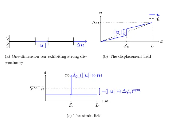
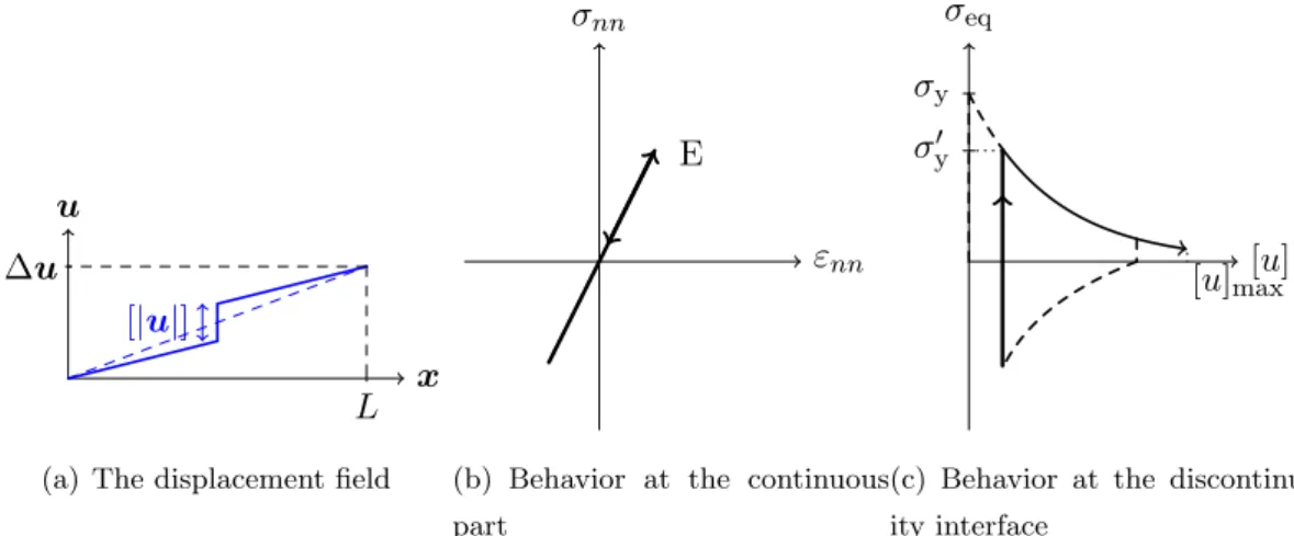
(17) Thèse de Yue Sun, Université de Lille, 2019. 5. to simulate the fatigue behaviors of concrete, the establishment of the model consists of two parts, which are the construction of the morphological model and the construction of the mechanical model. On the one hand, the used method for providing explicit representations on the morphological structures is referred to as the non-adapted mesh strategy. In regards to the concrete, the investigation scale is defined as the mesoscopic scale, specifically in millimeters and centimeters. At this scale, the concrete is a highly heterogeneous material, which exhibits aggregates, cement matrix, and macro-pores. The morphological structure is projected to a uniformed and unstructured mesh. In a case of a two-phase material (matrix and aggregates), the projection produces two types of elements: i) the elements that are entirely included in one phase, and ii) the elements that are crossed by the interfaces of aggregates. The latter type of elements carries a discontinuity in the strain field. This jump in the strain field is called the weak discontinuity. On the other hand, the used method to represent cracks is referred to as the strong discontinuity, i.e., jump in the displacement field. Many models have been introduced over the years which use the strong discontinuity. The governing law usually consists of a localization criterion, which decides the appearance of the cracks; and a softening law, which describes the degradation of the material. Aiming to produce the fatigue behaviors of concrete, a closure mechanism is considered in the model. With the fatigue behaviors of concrete concerned, there are a variety of possible explanations. For instance, the friction between the cracks, the additional dissipated energy, the irreversible crushed pores, and the release of the stresses that already exist during production. The benefit of the studied model is that the proposed mechanical behaviors at the local scale can be fairly simple and singular. Therefore, we attempt to develop a robust and efficient approach while revealing: • What are the minimum necessary ingredients for performing fatigue behaviors, which involves loss of stiffness, increasing permanent strain, hysteresis loops, etc... • What are the effects of each of these ingredients in the aspect of macroscopic responses as well as mesoscopic crack patterns.. This thesis consists of three chapters. In Chapter 1, a brief overview of the experimental facts and recent computational models is presented. Then the construction of the morphological model and mechanical model is detailed in Chapter 2. Referring to. © 2019 Tous droits réservés.. lilliad.univ-lille.fr.
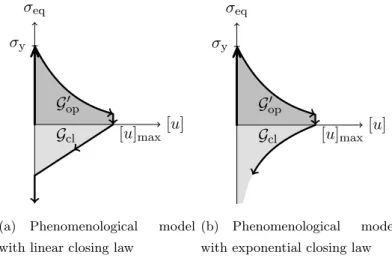
(18) Thèse de Yue Sun, Université de Lille, 2019. 6. Introduction. the “simple rules” of each element, see Fig. I .2, the mechanical behaviors of elements are defined upon a strong discontinuity of the mode-I. The element is split by the micro-crack, and the crack carries a vertical opening. A closure mechanism is then applied to the element representing a decreasing value of this separate. In this case, the closure of crack leads to additional dissipated energy. However, from the perspective of physical meaning, no friction is considered. Therefore, it is interesting to know if some of the fatigue behaviors can be observed if only the additional dissipated energy is considered, or if frictional sliding is one of the essential constituents of fatigue behaviors. Next, in Chapter 3, a closure mechanism is performed in the strong discontinuity of the mode-II. The microcracks of this type is comparable to a frictional sliding. The so-called closure represents a process that the crack slides back or even continues propagating in the opposite direction. In the case of the mode-II strong discontinuity, the friction between the lips of cracks is taken into consideration. Therefore, it is interesting to ascertain if more fatigue behaviors can be observed with the consideration of friction. For both types of strong discontinuity, mode-I and mode-II, the model is then examined by comparison with experimental tests, in which the experiment data is provided by Piotrowska (2013). The evaluation of the models is conducted in both axial loading and triaxial loading.. Major contributions The overall originality of this thesis is that several ingredients of the fatigue behaviors of concrete are discussed separately. Several major contributions of this study are mainly concentrated on the following points: • Based on former studies of the strong discontinuity of the type mode-I, the closure. mechanism is formulated to the model. The closure mechanism enables the additional dissipated energy while the friction between the cracks is not involved. Therefore, we can clarify that the additional dissipated energy along with the localization and traction-separation mechanism can be the minimum necessary ingredients for many main features of fatigue behaviors, such as the hysteresis loops and the stiffness recovery. In addition, the unilateral effect is also observed.. • The closure mechanism is then formulated to mode-II strong discontinuities, which includes the additional dissipated energy as well as the frictional sliding. Compared. with the previous assumption, we can deduce that the friction between the lips of crack plays a significant rule in fatigue behaviors. This model performs some main. © 2019 Tous droits réservés.. lilliad.univ-lille.fr.
(19) Thèse de Yue Sun, Université de Lille, 2019. 7. features of fatigue behaviors that the previous model does not achieve, such as the increasing permanent deformation. • Besides the macroscopic mechanical responses, the approaches of this thesis also shown some interesting evaluations of crack patterns. The morphological model exhibits a large number of finite elements and explicit representation of heterogeneities, the crack pattern is tortuous with branching and may be stopped by inclusions. Also, the crack closures may exist even in monotonic loadings.. © 2019 Tous droits réservés.. lilliad.univ-lille.fr.
(20) Thèse de Yue Sun, Université de Lille, 2019. 8. © 2019 Tous droits réservés.. Introduction. lilliad.univ-lille.fr.
(21) Thèse de Yue Sun, Université de Lille, 2019. Chapter II. State of art Contents 1. Introduction. . . . . . . . . . . . . . . . . . . . . . . . . . . . . . . . .. 9. 2. Experimental facts . . . . . . . . . . . . . . . . . . . . . . . . . . . . .. 10. Concrete behaviors under uniaxial and triaxial loadings . . . . . . . . 10. 2.2. X-ray tomographic investigations of concrete . . . . . . . . . . . . . . 13. 3. Advanced discretization techniques for image-based modeling . .. 15. 4. Modeling for the quasi-brittle materials . . . . . . . . . . . . . . . .. 17. 5. 1. 2.1. 4.1. Continuous approach with implicit cracks . . . . . . . . . . . . . . . . 17. 4.2. Discontinuous approach with explicit cracks . . . . . . . . . . . . . . . 27. Conclusion. . . . . . . . . . . . . . . . . . . . . . . . . . . . . . . . . .. 36. Introduction As one of the most widely used artificial materials, concrete is an important component. in civil engineering structures. As it is presented in the general introduction, we made the assumption that the apparent complexity of the mechanical behaviors of concrete is strongly linked with its complex heterogeneous structure. In this chapter, we will begin by providing a literature review on characteristics of concrete which are observed in experimental tests. Then the second part of this chapter presents an overview of two advanced discretization techniques. Finally, we shall introduce a brief bibliographic review of numerical models, which allow us to reproduce concrete behaviors.. © 2019 Tous droits réservés.. lilliad.univ-lille.fr.
(22) Thèse de Yue Sun, Université de Lille, 2019. 10. State of art. (a) Traction. (b) Compression. Figure II .1: Concrete behaviors under uniaxial traction (Terrien, 1980) and compression (Ramtani, 1990) loadings.. 2. Experimental facts Concrete is a material with complex behaviors. This section attempts to show ex-. perimental observations of concrete. The first part of this section presents some typical mechanical properties of concrete observed in experimental tests. The mechanical properties of concretes are discussed separately in uniaxial tests, i.e., without confining pressure, and in triaxial tests. Recent research has suggested that multiple mechanical behaviors of the concrete at the macroscopic scale are strongly influenced by the morphological structures of the material and the properties of the material components in smaller scales (Stamati et al., 2018a). Thus the second part of this section goes on to present a widely used technique that allows us to capture the characteristics of the material inside the concrete.. 2.1. Concrete behaviors under uniaxial and triaxial loadings. It is generally agreed that the failure behaviors of concrete under mechanical loadings are accompanied by the development of cracks. In the case of uniaxial loadings, the typical macroscopic responses of concrete are plotted in Fig. II .1. As shown in the figure, concrete is asymmetric under traction/compression loadings. It has brittle tensile behavior and is more ductile in compression. Fig. II .1 shows that in the first stage of the tensile loads, a linear response is ob-. © 2019 Tous droits réservés.. lilliad.univ-lille.fr.
(23) Thèse de Yue Sun, Université de Lille, 2019. Experimental facts. 11. served before the peak. According to recent research (Kishta, 2016), some micro-cracks will appear and diffuse throughout the material, particularly around the stress concentration area, for example, near the aggregates. These micro-cracks preferably develop in the direction perpendicular to the maximum extension. When the micro-cracks begin to coalesce and turn into macroscopic cracks, the material reaches its peak and turns to the post-peak stage. At this stage, the material rapidly loses its stiffness and strength. If cyclic loadings are applied, hysteresis loops and plastic deformations can be noticed.. The behavior of concrete in compression is rather ductile. The material has a much higher compressive strength than the tensile material, see Fig. II .1. Compression cracks are parallel to the loading direction due to the lateral expansion and induce the volume dilatation (Yazdani and Schreyer, 1988). At the post-peak stage, the material progressively loses its stiffness, hysteresis loops and plastic deformations can also be observed in cyclic compression loadings. The hysteresis phenomenon has several explanations. On the one hand, experimental observations reveal that micro-pores, micro-cracks, and residual stresses exist in virgin concrete due to the chemical hydration reaction. As degradation develops, residual stresses are released and disappear, resulting in permanent strain (Ramtani et al., 1992). On the other hand, plastic deformation and hysteresis loop are part of the consequence of friction between the lips of the cracks, i.e., the closure of cracks. As the imposed loading decreases, a few cracks remain open while others close, even for a state of zero stress.. Regarding the closure of cracks, it leads to another behavior of the concrete that can be observed in experimental tests, the unilateral effect (Mazars et al., 1990; Papa, 1996). The observed behavior of concrete is that when the applied loading switches from tension to compression, the damaged material in traction regains its stiffness in compression. Even though the material has been severely damaged in tension, the initial stiffness and strength remain unchanged in compression.. In addition to the behaviors of concrete under uniaxial loadings, many civil engineering applications are performed under triaxial conditions with different confining pressure, such as dams, bridge pillars, structural impacts, and radioactive waste treatment. It is therefore also essential to determine the mechanical behaviors under confining pressures.. Many researches are available in the literature which present concrete behavior under. © 2019 Tous droits réservés.. lilliad.univ-lille.fr.
(24) Thèse de Yue Sun, Université de Lille, 2019. 12. State of art. Figure II .2: Responses of concrete in terms of axial stress and deviatoric strain under different confining pressures (Malecot et al., 2010).. moderate confining pressure (Chuan-Zhi et al., 1987; Imran and Pantazopoulou, 1996; Kupfer et al., 1969a; Linhua et al., 1991; Pugh, 1973; Sfer et al., 2002) and high confining pressure (Gabet et al., 2008; Taliercio et al., 1999; Vu et al., 2009). A typical response of concrete under different level of confining pressure is shown in Fig. II .2.. The results of the triaxial tests shown in Fig. II .2 depicts a transition from quasibrittle to ductile behaviors. Concerning the hydrostatic pressure, an increase in confining pressure leads to an increase in material capacity, and a gradual stiffening is observed in the confining phase. More extremely, under very high confinement, concrete behaves like a non-cohesive granular stacking (Malecot et al., 2010; Piotrowska, 2013). The characteristics of cracks under different containment pressures also present different patterns. As plotted in Fig. II .3, the cracks are quasi-vertical under a relatively low confining pressure. And as the hydrostatic pressure increases to a very high level (> 100M P a), the cracks tend to be perpendicular to the loading direction. In between, inclined cracks are observed in a damaged concrete.. © 2019 Tous droits réservés.. lilliad.univ-lille.fr.
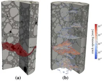
(25) Thèse de Yue Sun, Université de Lille, 2019. Experimental facts. 13. Figure II .3: Observed failure patterns of the concrete in different confining pressures (Piotrowska, 2013).. 2.2. X-ray tomographic investigations of concrete. As a heterogeneous material, concrete presents complex heterogeneities natures over a wide range of scales. These characteristics pose many challenges to experimental tests and numerical simulations because the properties of the constituents have significant influences on the macroscopic response of quasi-brittle materials. Several techniques are used to investigate the heterogeneous microstructure of the materials, such as the backscattered electron imaging of polished surface, and the X-ray micro-tomography (Piotrowska, 2013; Ren et al., 2015; Stamati et al., 2018a). X-ray micro-tomography is a non-destructive technique. Combined with image analysis technique, it could provide reliable representations of concrete heterogeneities at the mesoscopic scale in 3D (Hashemi et al., 2014; Lu et al., 2006; Poinard et al., 2011; Stamati et al., 2018a), and can access the damage mechanisms under loadings (Elaqra et al., 2007; Landis et al., 2003; Poinard et al., 2012; Wong and Chau, 2005). Recent researches provide a way to reproduce the material response by explicitly representing the heterogeneities of the meso-scale with the help of this technique (Stamati et al., 2018b), see Fig. II .4. In this manuscript, the material behaviors that we want to reproduce by numerical modeling focus mainly on: 1. The progressive failure of the material due to the initiation and propagation of cracks;. © 2019 Tous droits réservés.. lilliad.univ-lille.fr.
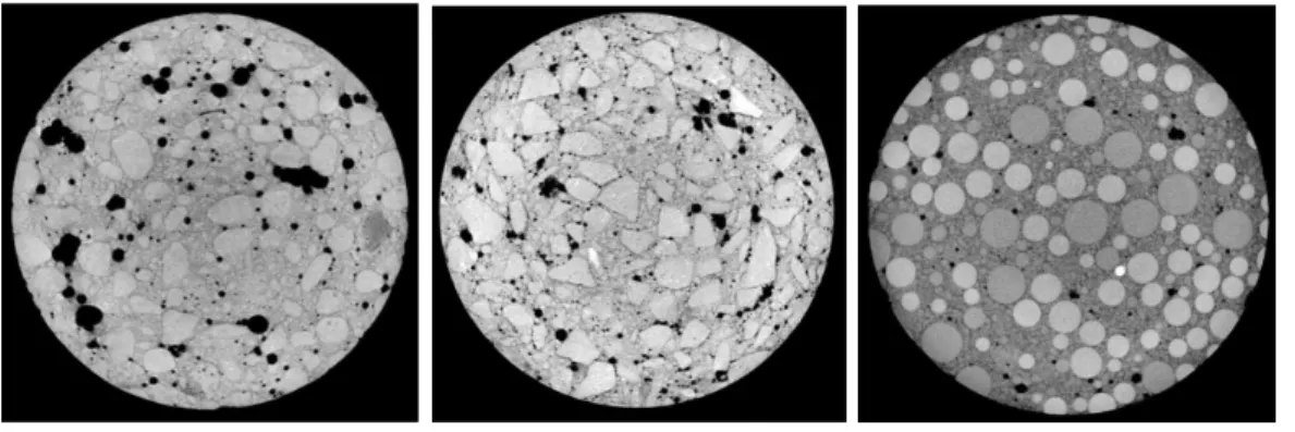
(26) Thèse de Yue Sun, Université de Lille, 2019. 14. State of art. Figure II .4: Comparison of crack patterns at post-peak stage between: (a) segmented 3D image of experimental scan and (b) numerical crack pattern Stamati et al. (2018b).. 2. The effect of heterogeneities at the mesoscopic scale, which leads to stress concentration and tortuous crack paths;. 3. The fatigue behaviors of the material, including the hysteresis phenomena and stiffness recovery, which are associated with crack closures;. 4. The triaxial behaviors of the material under confined pressures.. In order to verify the performances of the numerical simulation, it is interesting to compare it with an experiential result. Therefore, the experimental results that we used in this manuscript are provided by Piotrowska (2013), in which, experimental characterizations of concrete behaviors are well detailed. To establish the effect of the granular skeleton, three types of aggregates are used: the crushed aggregate, the rolled aggregate, and the glass balls, see Fig. II .5. The concretes are then applied to cyclic compressional loadings under different confining pressure (0, 50, 100, 200, 650 MPa). The comparison of the material responses between the numerical simulation and those of experimental results will be presented in the following chapters.. © 2019 Tous droits réservés.. lilliad.univ-lille.fr.
(27) Thèse de Yue Sun, Université de Lille, 2019. Advanced discretization techniques for image-based modeling. (a) Rolled aggregate concrete (b) Crushed aggregate concrete. 15. (c) Glass ball concrete. Figure II .5: Tomographic cross-sectional view of three concretes which exhibit different coarse aggregates (Piotrowska, 2013).. 3. Advanced discretization techniques for image-based modeling The broadly used civil engineering materials are found as heterogeneous materials. at the mesoscopic/microscopic scale, for example, the rocks, soils, shales, and concretes, etc.. Obviously, the overall characteristics of the material are strongly influenced by the size, shape, and distribution of the inclusion compositions or porous phases. Thus, a large amount of research has been devoted to investigating the relationships between the macroscopic responses of the material and its microstructural characteristics. X-ray tomography techniques allow us to obtain the geometrical information inside the heterogeneous material. In an attempt to combine the mechanical behaviors of the material with its compositions while considering the complex microstructure, discretization tools are needed to enable numerical simulations. Two categories of discretization techniques are discussed here: the non-conforming mesh generations and the conforming mesh generations. Based on raw implicit 3D images, different components of the material can be distinguished by image analysis, i.e., phase segmentation. Some efficient tools can be used such as thresholding from gray-scale images (Stamati et al., 2018a), or the level-set functions (Kamel et al., 2019b). Referring to the non-conforming strategy, it projects the implicit geometry onto an unstructured mesh. The geometrical information is inherited and taken into account by kinematic enhancement, namely the weak discontinuity. This strategy al-. © 2019 Tous droits réservés.. lilliad.univ-lille.fr.
(28) Thèse de Yue Sun, Université de Lille, 2019. 16. State of art. lows efficient automatic simulations without pre-processing. However, the non-conforming mesh method presents difficulties when attempting to capture all geometrical details with a uniformed mesh size. This limitation is visible in the case where the size of the finite element is larger than the narrowness between inclusions. Obviously, some geometrical information will be lost. On the contrary, the conforming strategy is very suitable for capturing microstructure details with refined finite elements.. Figure II .6: Illustration of the embedded weak discontinuity model for porous rocks using non-conforming mesh strategy, with solid phase colored in gray, pore phase in blue, and the enriched elements in red (Kamel et al., 2019a). The conforming discretization strategy allows producing high-quality meshes with automatic selective refinement. The use of uniform mesh elements to handle complex geometries may require a large number of elements. Thus the strategy of the conforming mesh method is to apply a size function to manage the geometrical features of micro-structure. Therefore, the narrowness between inclusions and the interface curvatures can be well described with refined finite elements. As it can be seen in Fig. II .6 and Fig. II .7, both discretization strategies are capable of automatically constructing models based on implicating 3D images. Compared with the non-conforming mesh strategy, the conforming mesh technique is adapted to capture more geometric details of the microstructure. And the porous phase can be treated naturally, as shown in Fig. II .7, which is not directly in the case of kinematic enrichment. The pore phase of a non-conforming model can only be approximately represented by low material. © 2019 Tous droits réservés.. lilliad.univ-lille.fr.
(29) Thèse de Yue Sun, Université de Lille, 2019. Modeling for the quasi-brittle materials. 17. Figure II .7: Illustration of the optimized conform mesh for porous rocks, with in the left: the global mesh for solid phase and pore phase; in the centre: the mesh of solid phase only; in the right: the mesh of pore phase only (Kamel et al., 2019a). stiffness parameters.. 4. Modeling for the quasi-brittle materials It is a common sense that the fracture is one of the most encountered failure modes for. engineering materials. Therefore, the prediction of material fractures plays a significant role in the context of civil engineering. Over the past two decades, many computational models have been proposed. These models provide tools to prevent structure failures, and also to understand and analyses the failure processes inside the material. In this section, we present an overview of computational models, including their main ideas as well as their advantages and limitations. And we classify these models into two categories: 1. Numerical models using continuous approach, i.e., the cracking description is implicit, 2. Numerical models using discontinuous approach, i.e., the cracking description is explicit.. 4.1. Continuous approach with implicit cracks. Aiming at describing the failure of brittle or quasi-brittle materials, the continuous approach is a kind of strategy that represents fractures as a process of strain localization and damage growth. It usually considers a hypothesis which assumes an equivalent. © 2019 Tous droits réservés.. lilliad.univ-lille.fr.
(30) Thèse de Yue Sun, Université de Lille, 2019. 18. State of art. homogeneous continuum over the representative volume. For instance, the averaged stress.. σM =. 1 V. Z. σ(x)d x.. (4.1). V. This hypothesis is named as Representative Volume Element (RVE). Under this assumption, the proposed model behaves as homogeneous material at the RVE scale:. σ M = f (εM ).. (4.2). Consequently, the representative volume only makes sense if the cross-section is much bigger than the size of cracks and heterogeneities. The displacement field is considered as continuous and without any explicit cracks. We present several models in the following part that belong to this category, and their main characters are also discussed.. 4.1.1. Theory of plasticity. The main idea of the theory of plasticity is to decompose the strain filed into two separate parts, ε = εe + εp ,. (4.3). where the elastic strain εe represents the elastic and undamaged material, and the plastic strain εp links with the cracked material which is irreversible. The stress filed is obtained by Hooke’s law: σ = C : εe = C : (ε − εp ),. (4.4). with C represents the stiffness of the material. The typical strain-stress relationship can be expressed in Fig. II .8. For the model exhibits only the plastic mechanisms, i.e., irreversible dissipated energies, the unloading path has exactly the same slope as the initial one.. © 2019 Tous droits réservés.. lilliad.univ-lille.fr.
(31) Thèse de Yue Sun, Université de Lille, 2019. Modeling for the quasi-brittle materials. 19. σ A. εpA. εeA. ε. εA. Figure II .8: Illustration of the basic idea of the theory of plasticity in a cyclic occasion. Applying the theory of plasticity to concrete-like materials (Chen and Chen, 1975; Dragon and Mroz, 1979; Etse and Willam, 1994; Grassl et al., 2002; Hofstetter and Mang, 1995; Menetrey and Willam, 1995), a basic constitutive plasticity model always consist of a yield function, a flow rule, a hardening law and/or softening law. A considerable amount of literature has proposed several classical and widely used yield functions, such as the Rankine principal stress criterion, which limits the tensile strength, and Drucker-Prager yield function, which adapts to compressional descriptions. The flow rule determines the evolution of the plastic strain rate. And the equipment of the hardening/softening law makes the plasticity models very suitable to describe failure conditions and development of permanent strain, and also material behaviors under biaxial/triaxial loadings. However, plasticity models along, lack the description of stiffness degradation due to the growth of micro-cracks, and other related behaviors such as the stiffness recovery and unilateral effect under cyclic or fatigue loadings. Thus the theory of plasticity is usually used by combining with other models, such as the damage model. . 4.1.2. Damage theory. The main idea of the damage theory is to introduce a damage variable D to describe the degradation of the material. The equation relating the stress-strain relationship in terms of the damage variable gives as: σ = (1 − D)C0 : ε. (4.5). where C0 represents the original stiffness.. © 2019 Tous droits réservés.. lilliad.univ-lille.fr.
(32) Thèse de Yue Sun, Université de Lille, 2019. 20. State of art. σ. E0 (1 − D)E0 elastic. damage D ∈ [0,1]. ε. Figure II .9: Illustration of the basic idea of the damage theory in a cyclic occasion. Depending on the damage describing is isotropic or anisotropic, the damage variable ¯ (for anisotropic damage). Referring can be a scalar D (for isotropic damage), or a tensor D to isotropic damage, the damage variable D varies from 0 to 1, where 0 represents a virgin state, and 1 represents a fully cracked state. In Fig. II .9 we propose a simple example where the assumption of the damage is elastic for stiffness degradation. It can be seen that the unloading path leads to the initial zero-zero strain-stress point, i.e., the model carries perfect reversible crack closures. The very first damage model applying to concrete failure was proposed in 1984 (Mazars, 1984). He proposed two separate damage variables Dt and Dc , for pure tension and pure compression case. And the damage variable D for general stress state is obtained by a linear combination described as: D = αt D t + αc D c .. (4.6). The Mazars model constructs independent control for uniaxial tension and compression loadings, and also shows a good approximation for biaxial tests. However, some of the main features of the cyclic loadings are not taken into accounts, such as the unilateral effect and the plastic strain. Based on the Mazars model, Comi and Perego (2001) proposed a damage model where the two damage variables have their separate activation criteria. And the unilateral effect with bulk stiffness recovery is included in the model thanks to the closure of micro-cracks. Even though still lack of plastic strain and volumetric dilatation, thus not adapted to describe failure behaviors under cyclic loading, the model provides accurate approximations to the biaxial data (Kupfer et al., 1969b).. © 2019 Tous droits réservés.. lilliad.univ-lille.fr.
(33) Thèse de Yue Sun, Université de Lille, 2019. Modeling for the quasi-brittle materials. 21. (a) Comparison between numerical and experimental (b) Uniaxial compression test and its multi-axial stress-strain relations for tensile loadings. numerical responses. Figure II .10: Responses of the damage model (Richard and Ragueneau, 2013) in traction and in compression.. Referring to the description of behaviors of the material under cyclic loadings, many recent researches of damage mechanics provide reliable solutions. Several models describe the fatigue behaviors by associating the damage with the number of cycle, which leads to the loss of stiffness and the decreasing of resistance of the material (Ramakrishnan and Malhotra, 1993; T.C. Hsu, 1981; Tepfers and Kutti, 1979). However, they have difficulties when extend to 3D problems and multiaxial problems (Ragueneau, 2007). And some approaches are only concerned in cyclic loadings with increasing amplitude, because the elastic strain does not exceed the previous maximum value. Thus they are not applicable for cyclic loadings with constant or variable amplitude.. Subjected to cyclic loadings, several damage mechanics models have been proposed which based on the thermodynamics with irreversible processes (Alliche, 2004; Ragueneau, 2007), or couple the damage with the friction or the plasticity (Desmorat et al., 2007a). The proposed model of Desmorat et al. (2007b) coupled the internal sliding and friction with the damage, which allows damage growths and structural failures in fatigue loadings. The asymmetric traction/compression behavior and stiffness recovery are addressed by applying micro-defects closure. And the model proposed by Richard and Ragueneau (2013) split the tension/compression behavior into two distinct parts, where the tensile behaviors are generated by isotropic damage, and the compressional behaviors are driven by non-. © 2019 Tous droits réservés.. lilliad.univ-lille.fr.
(34) Thèse de Yue Sun, Université de Lille, 2019. 22. State of art. σ. E0 (1 − D)E0 εp. ε. Figure II .11: Illustration of the basic idea of the plastic-damage theory in a cyclic occasion. associative plasticity mechanism with hardening effect. With the consideration of frictional sliding and closure function, permanent strain, dilatation, and a full and linear unilateral effect are taken into accounts. Complex uniaxial behavior can be obtained, see Fig. II .10. 4.1.3. Plastic-damage theory. It has been discussed in the previous part that plasticity theory and damage theory alone, each of them has its advantages and limitations. The combination of the plasticity theory and the damage theory gave birth to the plastic-damage theory. The stress-strain relationship for a classical plastic-damage theory writes as: σ = (1 − D) σ ¯ = (1 − D)C0 (ε − εp ),. (4.7). with σ ¯ is the effective stress and σ is the nominal stress. By considering a linear softening relationship and an elastic-damage assumption for stiffness degradation, a simple example of the plastic-damage theory is depicted in Fig. II .11. Referring to the damage part, the isotropic damage in more widely used (Bourgeois olling, 2004; Salari et al., et al., 2003; Gatuingt and Pijaudier-Cabot, 2002; Kr¨atzig and P¨ 2004) since the anisotropic damage itself is complex. The combination with the plasticity makes it rather more difficult to implement (Carol et al., 2001; Chaboche, 1992; Hansen et al., 2001; Krajcinovic, 1985).. © 2019 Tous droits réservés.. lilliad.univ-lille.fr.
(35) Thèse de Yue Sun, Université de Lille, 2019. Modeling for the quasi-brittle materials. 23. The selection of damage criteria is one of the critical issue related to the plastic-damage model. Denoted as the damage variable D, it can be driven by plastic stress/strain (Chow asek, 2006; Mazars, 1984; Ortiz, 1985), or based on the reand Wang, 1987; Grassl and Jir´ lease of fracture/damage energy (Lubliner et al., 1989b; Mazars and Lemaitre, 1985; Simo and Ju, 1987). As for the combined plasticity part, two main groups are developed: one of them combines plasticity based on the effective stress σ ¯ (undamaged space) (Grassl and Jir´ asek, 2006); another group comprises plasticity based on the nominal stress σ (damaged space) (Lubliner et al., 1989b). A classical plasticity theory has three essential parts: the yield criterion, the flow rule, and the hardening/softening law. The yield criterion, Mohr-Coulomb or Drucker-Prager or other criterion, usually have the form F (σ) = c, or F (¯ σ ) = c,. (4.8). where c denotes the cohesion and/or other associative constant. The main idea of the combination of plasticity and damage theory is to evaluate c through a plastic-damage variable. In the model of Lubliner et al. (1989a), for instance, the isotropic hardening law is represented by the increase of c, it will never decrease until it reaches a critical value. The vanish of the plastic-damage variable describes a strain-softening behavior.. 4.1.4. Crack band theory. The crack band theory is firstly proposed by Bazant and Oh (1983). The main idea of the crack band theory is to consider a fracture process zone with its width wc , the non-linear behaviors of the material are described in this zone, i.e., the crack band. The material remains an elastic behavior outside the band. The two parts of the material are linked with each other through a continuous strain field. As it is depicted in Fig. II .12(a), an actual crack morphology within a heterogeneous material is rather complex. The cracks tend to pass around the hard aggregates which leads to highly tortuous crack paths. The crack band of width wc in the model can be considered as a homogenization of the micro heterogeneities and micro-cracks. Hence the researched volume must be much bigger than the size of heterogeneities.. © 2019 Tous droits réservés.. lilliad.univ-lille.fr.
(36) Thèse de Yue Sun, Université de Lille, 2019. 24. State of art. (a) The actual crack morphology. (b) The equivalent crack band. Figure II .12: Illustration of the hypothesis of the crack band theory (Bazant and Oh, 1983). The model of Bazant and Oh (1983) uses three parameters to describe the fracture of the material: the fracture energy, the width of the crack band wc and the strength limit. And the model is capable of reproducing many features of the materials in different scales. However, the bandwidth dependency of the crack is not yet resolved. 4.1.5. Smeared crack theory. The first smeared crack theory that has been put into literation is the model proposed by Rashid (1968). Similar to the theory of plasticity that have been presented in the previous part, the smeared crack theory also decompose the strain field into two parts, an elastic part, and an inelastic part, which is called the crack strain in this theory, ε = εe + εc .. (4.9). And the stress field is obtained by applying the Hooke’s law, σ = Cεe .. (4.10). The illustration of the decomposition gives in Fig. II .13. Unlike the plasticity theory, that the development of the plasticity relies on yield criteria and flow rule, the crack strain is asek, 2011). A crack related directly to the traction transmitted across the crack plane (Jir´ will be initiated when the traction attains the strength of the material.. © 2019 Tous droits réservés.. lilliad.univ-lille.fr.
(37) Thèse de Yue Sun, Université de Lille, 2019. Modeling for the quasi-brittle materials. 25. Figure II .13: Representation of the basic idea of the smeared crack theory (Jir´ asek, 2011). Initially, the direction of the crack is assumed to be fixed. And the shear stress is formulated using the so-called retention factor (Suidan and Schnobrich, 1973). This assumption leads to drawbacks of stress-locking (Jirasek and Zimmermann, 1998a; Rots et al., 1985), which overestimate the remaining strength after the material comes to failure procedure, and the loss of objectivity upon mesh alignment (Rots et al., 1985). To the above ends, the use of classical smeared crack theory should remain cautious. Herein, a smeared theory with rotation crack direction was proposed by (Jirasek and Zimmermann, 1998a). However, the rotating model suffers from mesh-induced direction bias, which might lead to unstable simulations. These difficulties were finally overcome by (Jirasek and Zimmermann, 1998b). The model applies a standard rotating crack model at the early stage of the loading. Then turns to a damage-type description after the crack opening reaches the critical value.. 4.1.6. Phase-field Method. The main idea of phase-field method is that the crack propagates along the energy minimization trajectory. This idea is firstly proposed by Francfort and Marigo (G. A. Francfort and J. J. Marigo, 1998) (it is not called phase-filed then). The classical Griffith’s theory provides a criterion for crack propagation, but it has its limitations under these grounds: 1. Crack initiation, 2. Determinations of curvilinear or kinking crack paths, and branching angles, 3. Crack jumps along the crack path.. © 2019 Tous droits réservés.. lilliad.univ-lille.fr.
(38) Thèse de Yue Sun, Université de Lille, 2019. 26. State of art. These limitations are overcome by proposing variational methods based on energy minimization. Thus gave birth to a variational model for brittle fracture evaluations (Bourdin et al., 2008; Buliga, 1998; Dal Maso and Toader, 2002). After that, a Γ-convergence approximation is proposed in Bourdin et al. (2000), which is a numerical approximation of the variational approach to fracture. This approximation regularizes and diffuses a sharp crack surface into a diffused crack surface which is governed by a scalar auxiliary variable. The variable links the broken and unbroken material, and the equivalent crack surface is associated with the energy. Fig. II .14 illustrates this regularization. In the literature of Miehe et al. (2010a), a thermodynamically consistent phase-field model is proposed. It overcomes many difficulties for non-thermodynamically consistent models that, they are only reliable in particular situations such as monotonous loadings.. (a). (b). Figure II .14: Sharp and regularized diffuse crack topology in phase-field method with: (a) Sharp crack at x = 0, (b) Diffusive crack at x = 0 with length scale l (Miehe et al., 2010a). We show here a numerical example in Fig. II .15. A traction loading is applied to a cube which has a rigid sphere in it. We have a similar numerical example which will be detailed in a later section 8.1.. © 2019 Tous droits réservés.. lilliad.univ-lille.fr.
(39) Thèse de Yue Sun, Université de Lille, 2019. Modeling for the quasi-brittle materials. (a). (b). 27. (c). (d). Figure II .15: Evolution of the crack topology for a tensile test by using a phase-field method; the test is applied to a cube which exhibits a rigid sphere in the center (Miehe et al., 2010b). There are many advantages of the phase-field method that first, the model doesn’t require predefined cracks, and the propagations are also automatic. Second, it’s possible to have merging and branching cracks. For instance, in recent researches dealing with dynamic brittle fractures (Borden et al., 2012; Hofacker and Miehe, 2012; Li et al., 2016), some numerical applications show complex crack paths. And finally, it may couple with multi-physics. Some investigations have been put into literature, for example, the couuller, 2010) and the coupling of hydro-mechanical pling of thermo-mechanical (Kuhn and M¨ (Miehe et al., 2015). However, it also has some limitations: 1. The computational cost is expensive related to mesh size requirement, 2. The location of the crack tip may not reliable.. 4.2. Discontinuous approach with explicit cracks. In the previous section, it has been presented with several models that belong to the category of continuous approach. This section follows moves on to consider another group of models, which belong to the category of discontinuous approaches. Unlike the continuum approach, which is based on the hypothesis RVE, the discontinuous approach introduces displacement discontinuities in the displacement field or kinematic enrichment in the model. Both of them allow explicit representations of the cracks.. © 2019 Tous droits réservés.. lilliad.univ-lille.fr.
(40) Thèse de Yue Sun, Université de Lille, 2019. 28. State of art. 4.2.1. Linear Elastic Fracture Mechanics (LEFM). The Linear Elastic Fracture Mechanics (LEFM) is based on the framework of explicit discontinuities, which is firstly proposed by Griffith (1921). It establishes a theory according to which the strength of a quasi-brittle material actually depends on the size of defects and flaws. This method is therefore suitable for simulating materials with defects or micro-cracks. However, it does not describe the initiation and propagation of cracks. And it is only applied correctly if the mathematical discontinuity is fine enough in the fracture zone of the crack tip (Bazant and Planas, 1997). The Cohesive Zone Model (CZM) is developed based on LEFM. It is firstly proposed by Dugdale (1960) Barenblatt (1962), and then Hillerborg et al. (1976) enriched the model with the use of fracture energy, i.e., the fictitious crack model. Applied to concrete-like materials, this model consists of several traction displacement relationships. Discretization techniques were then developed for cohesive models. Regarding the modeling of cohesive cracks within the finite element framework, two main strategies can be presented from a asek, 2002). Depending on the occurred position general point of view (Bazant and Jir´ of displacement discontinuity is only between adjacent elements or arbitrary across the finite-element, two categories give as: 1. Discrete inter-element cracks In this approach, the displacement discontinuity occurs only between adjacent elements. If the crack path is not known in advance, a remeshing technique is required, and the cracks extend between elements. In the work of Xu and Needleman (1994) and Camacho and Ortiz (1996), a cohesive zone is inserted between the pairs of elements as an inter-element. And if the crack path is known a priori, the mesh can be constructed by tracing the trajectory of the discontinuity. Hence the crack path could coincide with the boundaries (Allix and Ladev`eze, 1992; Rots, 1991). This type of approach has been used for modeling quasi-brittle material such as concrete (Carpinteri, 1989) and ductile materials (Gullerud et al., 2000). 2. Discrete intra-element cracks In this approach, the displacement discontinuity is incorporated within the finite element at the element level, and the crack could pass through the mesh along an arbitrary trajectory. The model could consist of embedded discontinuities based on the assumed strain method (Armero and Linder, 2009; Belytschko et al., 1988; Dvorkin et al., 1990) , or extended finite element method which belongs to the family. © 2019 Tous droits réservés.. lilliad.univ-lille.fr.
(41) Thèse de Yue Sun, Université de Lille, 2019. Modeling for the quasi-brittle materials. 29. of partition unity method (Mo¨es et al., 1999; Wells, 2001). The cohesive zone model can be treated using the extended finite element method or embedded finite element method, which could make the model more flexible and robust. 4.2.2. Enriched kinematic based models. It is a common sense that the failure response of the material is always associated with the strain localization. Thus many models based on kinematic enhancement have been developed to capture the strain localization. In this part, two kinds of enhancements are considered: • The weak discontinuity enhancement, representing a strain discontinuity, is applied to the model explicit heterogeneities in the material (Belytschko et al., 1988; Roubin. et al., 2015; Sukumar et al., 2001), • The strong discontinuity enhancement, representing a displacement discontinuity. (Dvorkin and Assanelli, 1991; Simo et al., 1993), is applied to the model for cracks and fractures in the material.. These enhancements have been widely used in different models. For instance, the weak discontinuity enhancement proposes a methodology to model interfaces of material’s inclusions without meshing the internal boundaries (no-adapt meshing method) (Roubin et al., 2015; Sukumar et al., 2001). It has been improved by Belytschko et al. (1988), that two weak discontinuities are developed in the element to represent a localization band Fig. II .16. Referring to the strong discontinuity enhancement, the associated displacement field can be decomposed into two parts, i.e., a continuous field that exists on a coarse scale and has a standard continuum stress-strain relationship, and a discontinuous one that exists on a fine scale across the discontinuity interface. Many fundamental differences between enriched kinematic models are mainly associated with the treatment of the fine-scale kinematics and statics. In the following literature, we are going to discuss different families of enriched kinematic models according to their: 1. fine-scale enhancement strategies; 2. strong discontinuity approach kinematics (SDA); 3. support for additional displacement models.. © 2019 Tous droits réservés.. lilliad.univ-lille.fr.
(42) Thèse de Yue Sun, Université de Lille, 2019. 30. State of art. (a). (b). (c). (d). Figure II .16: Element with strong and/or weak discontinuity with: (a) one weak discontinuity, (b) two weak discontinuities, (c) one strong discontinuity, (d) one weak and one strong discontinuity (Roubin et al., 2015). Enhancement of the standard finite element interpolation In general, the fracture of quasi-brittle material contains highly localized deformation, and the failure zone is relatively concentrated and converged regarding the size of the material. For this reason, it is suitable to use the enriched kinematic based models, which can embed strong discontinuities in the displacement field. We can decompose the displacement field into two parts: a continuous part at a coarse-scale and a discontinuous part at a fine-scale. Depending on the strategies which deal with fine-scale enhancement, we can separate them into three families: Statically Optimal Symmetric Formulation (SOS), Kinematically Optimal Symmetric Formulation (KOS) and Statically and Kinematically Optimal Non-symmetric Formulation (SKON). Within the framework of embedded finite element method (EFEM), a comparison asek, 2000). And the between these gropes has been detailed put into the literature (Jir´ kinematics and statics enhancements employed to both EFEM and extended finite element method (XFEM) have been discussed in (Wu, 2011), in which four groups of enriched finite elements with non-uniform discontinuity modes are investigated. The three basic types of enhancement at the discontinuity are given as follows. 1. Statically Optimal Symmetric Formulation (SOS) This formulation is developed by many authors (Armero and Garikipati, 1996; Belytschko et al., 1988; Larsson et al., 1996; Sluys and Berends, 1998). The primary assumption of this formulation is that we do not introduce any displacement enhancement terms, hence all terms that associated with the displacement enhance-. © 2019 Tous droits réservés.. lilliad.univ-lille.fr.
(43) Thèse de Yue Sun, Université de Lille, 2019. Modeling for the quasi-brittle materials. 31. ment disappear. The interpolation matrix of the enhanced part of the strain field is chosen to satisfy the so-called zero mean condition (patch test), leading to a continuous stress field in the formulation. Under this assumption, it directly links the bulk stresses and tractions at the discontinuity, which gives a “natural” stress continuity condition. However, it doesn’t represent the kinematics of an opening crack. And this may lead to a drawback of spurious stress locking. It is worth noting that this formulation seems like never have been used in XFEM. 2. Kinematically Optimal Symmetric Formulation (KOS) Dealing with the problem of lacking accurate representations of strong discontinuity kinematics at a fine-scale in SOS enhancement, KOS reproduces one with meaningful description (Lotfi and Shing, 1995). The enhanced strain interpolation matrix is obtained by the symmetrical kinematics operator ∇s . However, unlike SOS, KOS. enhancement has a poor solution to the stress field around the failure surface, especially for a coarse mesh. And this may lead to pathological stress field that the bulk stresses lying outside the discontinuity interface before failure occurs (Wu et al.,. 2015). 3. Statically and Kinematically Optimal Non-symmetric Formulation (SKON) The combination of advantages of the two previous approaches gives birth to the SKON enhancement. It takes the optimal static and kinematic equations and provides a better numerical simulation. It was outlined in Dvorkin et al. (1990) Simo and Rifai (1990) and then fully detailed in Oliver (1996a). The actual and the virtual strain field are handled in different assumption, that the prior is under the KOS consideration and the latter satisfies the zero mean condition of SOS enhancement. As a result of this combination, though it losses the symmetric description of the stiffness matrix, the SKON method has “natural” traction continuity across the discontinuity, and a reasonable stress field around the failure surface even for a coarse mesh. The problem of spurious stress locking effect is also fixed. Another benefit of the SKON approach is that it demands no specific characteristic length of the asek, 2000). localization (Jir´ The later two enhancement, KOS and SKON, have been used in both EFEM and XFEM. As it is presented in the literature Jir´ asek (2000) and Wu (2011), the SKON approach is always suggested due to its better element performance in providing robust and reliable results, no matter in the framework of EFEM or XFEM. In the following part. © 2019 Tous droits réservés.. lilliad.univ-lille.fr.
(44) Thèse de Yue Sun, Université de Lille, 2019. 32. State of art. of the redaction, this is also the chosen strategy in our numerical simulations. Strong discontinuity approach (SDA) The SDA has been firstly proposed by Simo et al. (1993) and then in Armero and Garikipati (1996), and has been widely organized and developed within the framework of enriched kinematics based models. It is applied to the simulation of the failures behaviors of quasibrittle materials over last years (Armero and Garikipati, 1996; Oliver, 1996b, 2000; Simo et al., 1993). The three main features of SDA (Kishta, 2016; Oliver et al., 2001) are listed in the followings: • The use of local continuum constitutive laws which is equipped with strain softening, • The consideration of strong discontinuity kinematics, i.e., the appearance of displacement jumps in the continuum kinematics,. • The strong discontinuity analysis. Within the framework of mathematics and mechanics, the main objective of SDA is to develop a compatible relationship between the strong discontinuity kinematics and the continuum constitutive equations. It should respect the following requirements (Roubin, 2013): • The stress field should remain bounded over the domain Ωe , • The continuity of the traction vector across the discontinuity interface should be guaranteed.. In this part, two main groups of the strong discontinuity analysis are discussed: 1. Continuum Strong Discontinuity Approach (CSDA) The main idea of this approach is to use a continuum constitutive model (isotropic scalar continuum damage models, plasticity models, etc.) over the finite element. This approach proceeds a constitutive model that returns bounded stresses when the unbounded strain field is introduced.. A parameter κ is used to regularize. the Dirac’s delta function, whose objective is to ensure the interpolation functions smooth enough. This approach has been well detailed in Oliver (1996b) and Oliver et al. (2002). 2. Discrete Strong Discontinuity Approach (DSDA) In this approach, a continuum constitutive law is applied over the bulk volume while a. © 2019 Tous droits réservés.. lilliad.univ-lille.fr.
Figure


+7

Documents relatifs