O
pen
A
rchive
T
OULOUSE
A
rchive
O
uverte (
OATAO
)
OATAO is an open access repository that collects the work of Toulouse researchers and makes it freely available over the web where possible.This is an author-deposited version published in: http://oatao.univ-toulouse.fr/ Eprints ID : 15992
To link to this article : DOI: 10.4028/www.scientific.net/SSP.251.106 URL : http://dx.doi.org/10.4028/www.scientific.net/SSP.251.106
To cite this version :
Scheller, Johannes and Jodin, Gurvan and Rizzo, Karl Joseph and Duhayon, Eric and Rouchon, Jean-François and Triantafyllou, Michael S. and Braza, Marianna A Combined Smart-Materials Approach for Next-Generation Airfoils. (2016) Solid State Phenomena, vol. 251. pp. 106-112. ISSN 1012-0394
Any correspondence concerning this service should be sent to the repository administrator: [email protected]
A combined smart-materials approach for next-generation airfoils
Johannes SCHELLER
1, 3 a *, Gurvan JODIN
1, 3 b *, Karl-Joseph RIZZO
1 c,
Eric DUHAYON
1 d, Jean-Francois ROUCHON
1 e,
Michael TRIANTAFYLLOU
2 fand Marianna BRAZA
3 g1
LAPLACE, 2, Rue Charles Camichel,- BP 7122, F-31071 Toulouse, France 2
MIT, 77 Massachusetts Avenue, 02139 Cambridge, MA, USA 3
IMFT, Rue du professeur Camille Soula, F-31400 Toulouse, France a
[email protected], [email protected], [email protected], d
[email protected], [email protected], [email protected], g[email protected]
Keywords: Aerodynamics, Morphing, Piezoelectricity, Shape-memory Alloys
Abstract. This article will present a morphing wing actuated using both surface embedded Shape memory alloys (SMAs) and trailing edge Macro-fiber composites (MFCs). This combination enables the airfoil to simultaneously achieve large scale deformations at low frequencies as well as rapid actuation with a limited amount of displacement. Thereby not only can the shape of the airfoil be optimized in function of the current mission profile but also the shear layer can be influenced. Each actuator is modelled using both a finite element and/or an analytical model and the results will be verified experimentally.
Introduction
Today’s rigid airfoil geometries are usually the result of compromise in the design process optimizing the airfoil for some parts of the mission profile. In order to circumvent this disadvantage control surfaces are used. Unfortunately these are usually characterized by poor aerodynamic performance and efficiency. Morphing structures potentially hold the key to solve this problem. Hence, wing deformation studies are subject of much interest in the aerospace domain and recent advances made in the field of smart-materials have renewed this interest [1]. The Electro-active morphing for micro-air-vehicles (EMMAV) research program aims at optimizing the performance of micro-air-vehicles in realistic environments via electroactive morphing. During the course of this project a prototype NACA 0012 wing was developed with embedded Shape memory alloys (SMAs) and trailing-edge piezoelectric actuators enabling both large deformations (~10% of the chord) at limited frequency (<1Hz) and small deformations (several μm) at high frequencies (≤100Hz) [4]. The characteristics of the SMA technology, which were activated using the well understood Joule effect, make it especially suitable to optimize the shape of the wing and to control the flight [2, 6]. The high-frequent but low amplitude piezoelectric technology on the other hand is useful to produce trailing-edge vortex breakdown [11].
As an evolution of this design a NACA 4412 based airfoil with embedded surface actuated SMAs and a high-frequency vibrating trailing edge (HFVTE) using MFC actuators is proposed. In contrast to conventional piezoelectric materials MFCs are significantly more flexible allowing for easier integration in the target structure [9]. MFCs, while being a relatively new type of piezoelectric actuator, have already been used in order to change/control the camber of an airfoil, to twist rotor blades or as control surfaces for micro airvehicles (MAVs) [8, 9]. Erturk studied the energy harvesting capabilities of MFC actuators and developed an analytical model based on the Euler-Bernoulli beam theory [9]. Pankonien et al. studied the combination of MFC actuators with SMAs in what they called a synergistic smart-morphing aileron [3].
In comparison to the previous design the deformable section of the NACA4412 prototype was reduced by 50% in accordance with industrial demands. Furthermore, to approach actual wing designs the airfoil surface is made out of an aluminum alloy. Whereas, as previously stated, the use of SMAs for wing deformation studies is already well understood, the majority of the designs are based on the use of compliant materials. The issues arising when using less compliant materials and the proposed solutions have been discussed in Scheller et al. [5].
This work is developed as follows: in a first part the quasi-static camber control using the surface embedded SMAs is detailed, an analytical model is introduced to estimate the achievable deflection of the actuator and the experimentally determined airfoil performance is shown. In a second part the HFVTE’s design and the adapted MFC model are highlighted. Finally the results are discussed and a short conclusion is drawn.
Quasi static camber control
The designed actuation system aims at the adaptation of the airfoil profile under aerodynamic loads. This actuation is applied at the trailing-edge of the airfoil in order to change its camber. The trailing edge tip is displaced by +/-5 % of the chord by activating the SMA wires embedded under the airfoil skin. To provide both upwards and downwards bending, two antagonistic actuators are implemented, one on the extrados one on the intrados. In order to ensure an overall unchanged length a center bar fixes the trailing-edge position.
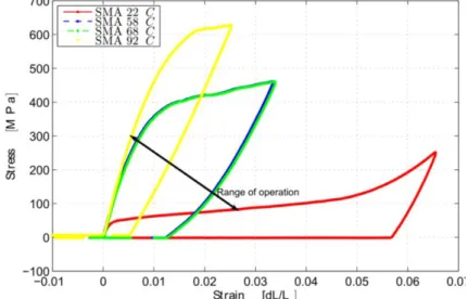
Figure 1 Range of operation of the SMA wires (ϕ=1 mm) determined experimentally
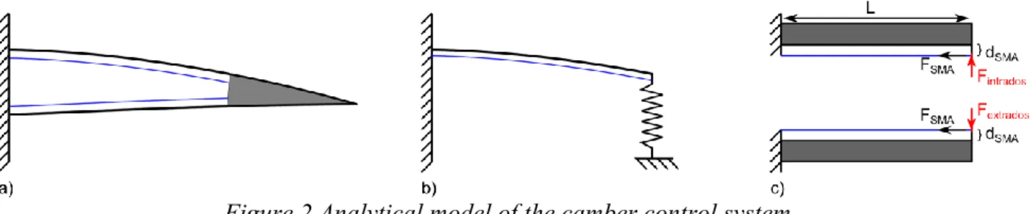
The SMA wires are activated via a temperature change, they have both a hot temperature and a low temperature stable crystalline phase. Whereas the low-temperature phase is easily deformable the high temperature phase is significantly stiffer. If the material is deformed in the cold temperature phase a strain change occurs during the temperature increase induced phase change; this is the so called shape memory effect (SME). The experimentally determined stress-strain characteristics of the SMA wire used in this paper are presented in Figure 1. Based on these measurements an analytical model of the deflection of SMA actuated trailing edge can be developed. Figure 2a) illustrates the modeled section. The activated section can be modeled as a beam and the passive section as a spring with a constant k 3YI L3(Y being the Young Modulus of the airfoil skin, I being the area moment of inertia and L being the length of the activated section), as illustrated in Figure 2b), neglecting the compliant mechanism and the center bar as they are assumed perfectly flexible. Hence, the total beam deflection is the result of the superposition of the beam deflection due to the applied moment by the SMA wires embedded at a distance dSMA of the intrados/extrados
Figure 2 Analytical model of the camber control system
In order to model this system, the spring reaction has to be modelled. This can be done as illustrated in Equation (1). In this Equation α is the angle between the intrados and the extrados at the end of the activated section of length L, Y is the Young’s modulus of the airfoil skin and I is the associated area moment of inertia. The moment M can be calculated knowing the distance dSMA of the SMA
wires with respect to the neutral plane and the associated force F which can be deduced from the experimental measures shown in Figure 1.
YI RL k R YI ML spring action 3 ) cos( 2 ) cos( 2 3 Re (1)
Resolving this Equation the reaction force R can be determined and hence the displacement of the intrados and extrados can be calculated. This was done for the prototype previously introduced and the results of which can be seen in Figure 3. The total span of the NACA4412 prototype is 200 mm, the thickness the airfoil skin is 1 mm, the chord length 425 mm, the length of the activated section is
180 mm and the length of the passive section holding the HFVTE is 90 mm. Assuming a force F=200 N in the SMA wires the displacement was found to be ≈+-21 mm for a quarter section as a
total of four wires are distributed in the airfoil.
Figure 3 Analytically determined deflection with σ =250 MPa superposed with the CAO of the airfoil; colorbar represents the absolute value of the displacement in y-direction
Figure 4 FEM simulations of the deflected trailing edge with σ =250 MPa (left) and σ =215 MPa (right)
In order to fortify the confidence in the actuation mechanism the activated section was modelled using the commercially available finite element solver ANSYS. Similar to the analytical model a quarter section was modelled representing the airfoil skin using beam elements and the SMA wires using cables exerting a constant force. An iterative procedure then calculates via a pseudo-Newton algorithm the stress-strain characteristic of the SMA wires until converging on their characteristic behavior shown in Figure 1. The results of this model, shown in Figure 4, allows to verify the behavior of the compliant sliding mechanism. As can be seen in this Figure plotting the
displacement for both intrados/extrados activation a difference exists between the forces required to actuate the upper and lower airfoil skin. This can be attributed to the inherent NACA 4412 geometry.
As both the analytical and numerical models demonstrated the feasibility of the actuation mechanism a prototype was constructed. To verify its actuation capacity the tip displacement was measured using a Mitutoyo linear measurement. The results of these experiments can be seen in Figure 5.
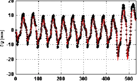
Figure 5 Displacement of the NACA 4412 airfoil measured (red) and reconstructed using the embedded strain gages (black)
In addition to measuring the displacement, strain gauges embedded on the airfoil skin at the beginning of the deformable section also allowed to estimate the position of the trailing edge in real time. Two conclusions can be drawn from the here presented models and experiments: first a 10 % deflection of the trailing edge with respect to the chord length is possible and second both numerical and experimental results show a good correspondence.
High-frequency vibrating trailing edge
The goal of the MFC actuators in the HFVTE is to generate displacements ≥1 mm at frequencies of around 100 Hz in order to influence the aerodynamic coefficients and reduce both noise and drag. As previously mentioned, the here selected solution is based on piezoelectric fiber composites.
Figure 6 Illustration of the MFC’s internal setup (left) and bimorph’s design (right)
These MFC actuators are piezoelectric fibers encapsulated with a network of interdigitated electrodes inside an epoxy resin as illustrated in Figure 6. This Figure also illustrates the actuator setup using a flexible substrate material onto which the MFCs are glued on either side using DP460 epoxy adhesive. The alternating extensions of the two MFCs creates a bending moment inside the structure. Hence, the MFC’s displacement is mechanically amplified. The MFC actuators used in this study are commercially available through Smart Material GmbH.
In order to predict the behavior of the MFC bimorph an analytical model based on the approach described by Ballas [7] has been developed. This approach assumes small deformations and follows the assumptions made by the Euler-Bernoulli beam theory and the theory of linear piezoelectricity. In which case the governing equation of the actuator shown on the right side of Figure 6 is given as:
) , ( ) , ( ) , ( ) , ( 2 2 2 2 t x f x t x u c t t x u A x t x M a (2) where ρ is the density of the beam, A is the cross-sectional area and ca is the beam damping. Using
In Equation (3) Y is the Young modulus of the materials, I is the second moment of area, V(t) is the time varying voltage and Γ is the piezoelectric coupling coefficient given by Equation (4).
) ( ) , ( ) , ( 2 2 V t x t x u YI TzdA t x M
(3) 2 1 2 33 2 z z el fibers fiber MFCw n z Y d (4) Equation (4) corresponds to the actuation of a single MFC actuator. In this equation YMFC is theYoung Modulus of the MFC actuator, nfibers is the number of piezoelectric fibers, wfiber is the width
of a single fiber, z1 and z2 correspond to the distance of the fibers’ bottom and top to the neutral
layer respectively, d33 is the piezoelectric coefficient and Δel is the distance between two electrodes.
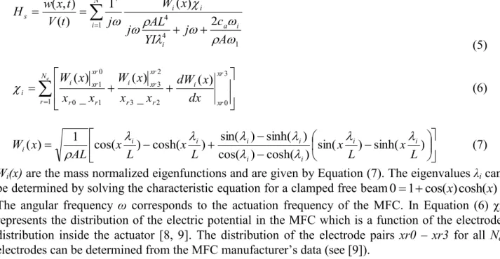
Equation (2) can be solved to yield the transfer function of the MFC actuated bimorph as given in Equation (5), where χi accounts for the distribution of the electrical potential inside the MFC which
is a function of the electrode distribution inside the actuator [8, 9].
N i a i i i i s A c j YI AL j x W j t V t x w H 1 1 4 4 2 ) ( ) ( ) , ( (5)
Ne r xr xr i r r xr xr i r r xr xr i i x x dWdxx x W x x x W 1 3 0 2 3 2 3 1 0 0 1 ( ) _ ) ( _ ) ( (6) sin( ) sinh( ) ) cosh( ) cos( ) sinh( ) sin( ) cosh( ) cos( 1 ) ( L x L x L x L x AL x W i i i i i i i i i (7)Wi(x) are the mass normalized eigenfunctions and are given by Equation (7). The eigenvalues λi can
be determined by solving the characteristic equation for a clamped free beam01cos(x)cosh(x). The angular frequency ω corresponds to the actuation frequency of the MFC. In Equation (6) χi represents the distribution of the electric potential in the MFC which is a function of the electrode distribution inside the actuator [8, 9]. The distribution of the electrode pairs xr0 – xr3 for all Ne
electrodes can be determined from the MFC manufacturer’s data (see [9]).
Table 1 Characteristics of the tested MFC bimorphs and unimorphs
Plot reference Substrate Thickness MFC type
4312 b 0.3 Acier 0.30 mm 4312 (60 mm x 21 mm)
8514 u 0.25 Acier 0.25 mm 8514 (101 mm x 20 mm)
8514 u 0.5 Acier 0.50 mm 8514 (101 mm x 20 mm)
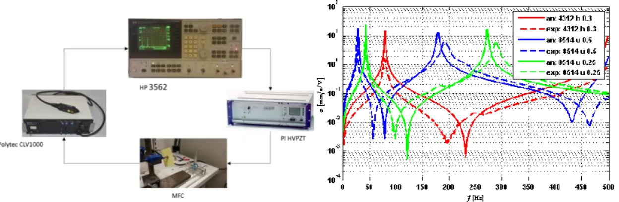
To validate the previously developed model a set of measurements was executed using different MFCs, different substrate thicknesses and different setups. The configurations are summarized in Table 1. The velocity of the unimorph and bimorph actuators has been measured using a Polytec CLV-1000 laser vibrometer, the actuators’ power supply was done using a high voltage amplifier PI HVPZT and a signal analyzer, HP 3562, both provided the control signal and stored the measurements. The experimental setup is summarized on the left hand side of Figure 7.
Figure 7 Experimental setup and frequency response of the MFCs described in Table 1
As can be seen by comparing the experimental results to the analytically determined frequency response in Figure 7 a good correspondence exists between model and experiment. A difference in amplitude can be observed for the MFC in bimorph configuration which can be attributed to the difference in amortization. Overall the measurements coincide well with the developed model and allow to estimate the resonance frequency and the velocity magnitude.
Conclusion and discussion
This paper described the design of a NACA 4412 prototype airfoil actuated using SMA and MFC actuators. The actuator design with the different target objectives (≈10% displacement and f≤100 Hz at 1 mm of deflection) has been described and both analytical and numerical models have been developed. The designed airfoil is currently being evaluated in the S4 windtunnel of IMFT and whereas the detailed evaluation of the results especially the benefit of the hybridation of the actuation system is still in progress preliminary results are quite promising. The SMA based actuation allows for a precise lift/drag control. The high-frequency MFC based actuation also shows promise yet its interpretation is more challenging as the main conceived function is to reduce the shear layer vortices.
References
[1] S. Barbarino, O. Bilgen, R.M. Ajaj, M.I. Friswell, D. J. Inman, A Review of Morphing Aircraft, Journal of Intelligent Material Systems and Structures (2011) 22-823
[2] F.T. Calkins, J.H. Mabe, Shape Memory Alloy Based Morphing Aerostructures, Journal of Mechanical Design (2010) Vol. 132 111012
[3] Pankonien, Alexander M., Cassio T. Faria, and Daniel J. Inman. "Synergistic smart morphing aileron." Proceedings of 54th AIAA/ASME/ASCE/AHS/ASC Structures, Structural Dynamics, and Materials Conference. 2013.
[4] M. Chinaud, A. Boussaid, J.F. Rouchon, E. Duhayon, E. Deri, D. Harribey, M. Braza, Thermo-mechanical coupling in Nitinol. Application to an electro-morphing plate, 20th International Conference on Electrical Machines (2012)
[5] J. Scheller, K.J. Rizzo, G. Jodin, E. Duhayon, J.F. Rouchon, M. Braza, A hybrid morphing NACA4412 airfoil concept, IEEE International Conference on Industrial Technology (2015) [6] C. Lexcellent, Shape-memory Alloys Handbook, Wiley-ISTE, March 2013, ISBN:
978-1-84821-434-7
[7] Dr. Rüdiger, G. Ballas, Piezoelectric Multilayer Beam Bending Actuators, Static and Dynamic Behavior and Aspects of Sensor Integration, (2007) ISBN: 978-3-540-32641-0
[8] A. Erturk, O. Bilgen, M. Fontenille, and D. J Inman. Piezoelectric energy harvesting from macro-fiber composites with an application to morphing wing aircrafts. In Proceedings on the 19th international conference of adaptive structures and technologies, Monte Verità,
[9] O. Bilgen, K. B. Kochersberger, D. J Inman, and O. J Ohanian III. Macro-fiber composite actuated simply supported thin airfoils. Smart Materials and Structures, 19(5):055010, 2010. [10] IEEE standard on piezoelectricity. ANSI IEEE 1987-176, 1988. doi: 10.1109/IEEESTD.
1988.79638.
[11] M. Chinaud, J. Scheller, J. F. Rouchon, E. Duhayon, and M. Braza, “Hybrid Electroactive Wings Morphing for Aeronautic Applications,” Solid State Phenomena, vol. 198, pp. 200–205, 2013.