Canister free videogrammetry system for thermal vacuum and space applications
Texte intégral
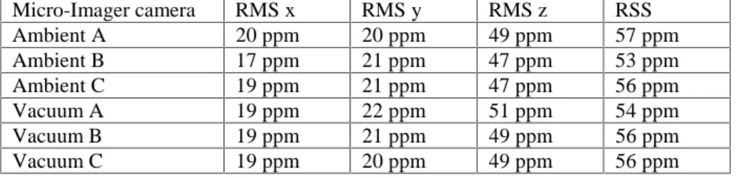
Figure


Documents relatifs
m Dessine ²le nombre ²de ²jeton$
b) Faire de même pour chacune des autres pièces en donnant une expression de la surface de moquette nécessaire en fonction des dimensions données. 2) Développer si possible et
Lorsque la couleur est validée, le joueur pose son pion sur la première case du chemin ayant cette même couleur. Si la réponse n’est pas validée par les autres joueurs grâce à
Or lorsque le Roi aura libéré l’avant-dernier voleur, il aura compté un nombre d’emplacements égal à la somme 1+2+3+…+n-1 puisque seul le dernier voleur ne sera pas libéré
Chaque joueur lance le dé à tour de rôle et avance du nombre de cases indiqué en respectant les consignes des cases « Jack » et des cases « ogre ». Celui qui totalise le plus de
quand on tombe sur un oiseau, il faut lui donner le nombre de pains indiqué. la partie s’arrête quand un enfant est arrivé dans
[r]
[r]
