ÉCOLE DE TECHNOLOGIE SUPÉRIEURE UNIVERSITÉ DU QUÉBEC
ARTICLE-BASED THESIS PRESENTED TO
ÉCOLE DE TECHNOLOGIE SUPÉRIEURE
NATIONAL UNIVERSITY OF SCIENCE AND TECHNOLOGY “MISIS” (COTUTORSHIP)
IN PARTIAL FULFILLMENT OF THE REQUIREMENTS FOR THE DEGREE OF DOCTOR OF PHILOSOPHY
Ph. D.
COTUTORSHIP RUSSIA-QUÉBEC
BY
Sergey DUBINSKIY
Ti-Nb-(Zr,Ta) SUPERELASTIC ALLOYS FOR MEDICAL IMPLANTS:
THERMOMECHANICAL PROCESSING, STRUCTURE, PHASE TRANSFORMATIONS AND FUNCTIONAL PROPERTIES
MONTREAL, 10 DECEMBER 2013
© Copyright reserved
It is forbidden to reproduce, save or share the content of this document either in whole or in parts. The reader who wishes to print or save this document on any media must first get the permission of the author.
BOARD OF EXAMINERS
THIS THESIS HAS BEEN EVALUATED BY THE FOLLOWING BOARD OF EXAMINERS
Mr. VLADIMIR BRAILOVSKI, Professor, Thesis Supervisor
Département de Génie Mécanique at École de Technologie Supérieure
Mr. SERGEY D. PROKOSHKIN, Professor, Thesis Co-supervisor
Department of Plastic Deformation of Special Alloys at National University of Science and Technology “MISiS” (Moscow, Russia)
Mrs. NICOLA HAGEMEISTER, Professor, President of the Board of Examiners
Département de Génie de la Production Automatisée at École de Technologie Supérieure
Mr. PATRICK TERRIAULT, Professor, Member of the jury
Département de Génie Mécanique at École de Technologie Supérieure
Mr. MAMOUN MEDRAJ, Professor, Member of the jury (external)
Mechanical and Industrial Engineering Department at Concordia University
THIS THESIS WAS PRESENTED AND DEFENDED
IN THE PRESENCE OF A BOARD OF EXAMINERS AND PUBLIC 15 NOVEMBER 2013
ACKNOWLEDGEMENT
First and foremost I would like to express my gratitude to Professors Vladimir Brailovski and Sergey Prokoshkin for giving me the unique opportunity to work on this project, for general and practical supervision and, especially, for inspiring me in tough times. I am thankful to them for their excellent example of teamwork, in which I am lucky to be involved.
I would like to thank Drs. Karine Inaekyan and Andrey Korotitskiy for invaluable practical help and encouragement at all times.
I would also like to thank Michel Drouin, Serge Plamondon, Jean-Guy Gagnon, Radu Romanica and Patrick Sheridan for technical support and useful advice.
I am grateful to all my colleagues: Vadim, Jonathan, Yulia, Charles F., Thoma, Charles S., Simon, Alena, Daniel and Yan B. for the pleasure of working together. I am very appreciative of the patience with which Yann F., Pierre-Luc and Yannick were answering my hundreds of questions.
Last, but not least, I would like to express my gratitude to all my family for their great patience and support during all these years.
Ti-Nb-(Zr,Ta) SUPERELASTIC ALLOYS FOR MEDICAL IMPLANTS: THERMOMECHANICAL PROCESSING, STRUCTURE, PHASE
TRANSFORMATIONS AND FUNCTIONAL PROPERTIES Sergey DUBINSKIY
RÉSUMÉ
Le but de ce projet est de développer une nouvelle classe de matériaux d'implants orthopédiques, qui combinerait une excellente biocompatibilité du titane pur avec une compatibilité biomécanique exceptionnelle d'alliages à mémoire de forme Ti-Ni. Les candidats les plus appropriés pour un tel rôle sont les alliages à mémoire de forme Ti-Nb-Zr et Ti-Nb-Ta de type beta métastable. Cette classe de matériaux a été développée tout récemment et l'influence du traitement thermomécanique sur leur structure et leurs propriétés fonctionnelles ne faisaient pas encore objet d'aucune étude approfondie. Par conséquent, ce projet est axé sur les relations entre la composition, la microstructure et les propriétés fonctionnelles des alliages superélastiques Ti-Nb-Zr et Ti-Nb-Ta pour applications biomédicales. L'objectif principal est d'améliorer les propriétés fonctionnelles de ces alliages, plus particulièrement les propriétés superélastiques et la résistance à la fatigue, grâce à l'optimisation de la composition des alliages et de leur traitement thermomécanique.
Premièrement, cette thèse prouve que la structure et les propriétés fonctionnelles des alliages à mémoire de forme à base de Ti-Nb peuvent être efficacement contrôlées par un traitement thermomécanique, y compris par la déformation à froid suivie de traitement thermique de recuit et de vieillissement. Il est également démontré que la formation d’une structure nano-sous-granulaire mène à une amélioration significative de la superélasticité et de la résistance à la fatigue de ces alliages. L'influence du vieillissement sur la cinétique de précipitation de la phase ω et, par conséquent, sur les propriétés fonctionnelles des alliages Ti-Nb-Zr et Ti-Nb-Ta est également observée.
Basant sur les résultats obtenus, les régimes du traitement thermomécanique optimisé résultant en une meilleure combinaison des propriétés fonctionnelles sont recommandés pour chaque alliage, d’un point de vue de matériau pour implants orthopédiques.
Deuxièmement, un dispositif de traction miniature pour une étude in situ à basse température dans la chambre d’un diffractomètre à rayons X a été développé et utilisé. Une étude comparative sur les caractéristiques des transformations et de l'évolution du réseau cristallin dans des conditions du contrôle de déformation et de balayage en température entre -150 et +100oC a été réalisée in situ. Les paramètres de la maille cristalline des phases β et α” ont été calculés dans une plage de température étudiée, ce que nous a permis de conclure que plus la température est élevée, plus la déformation qui accompagne la transformation des phases α”→β est faible. On a également constaté que le chargement à basse température mène à la formation additionnelle et la réorientation de la phase α”, tandis que l'application de la charge lors du chauffage modifie la séquence des transformations. L’élargissement et le
rétrécissement réversible des pics de la phase β qui sont observées lors du balayage en température sont le résultat direct de l’apparition et de la disparition des micro-contraintes causées par la transformation martensitique thermoélastique réversible.
Mots-clés: alliages à mémoire de forme, alliages de titane, biomatériaux, traitement thermomécanique, laminage, traitement thermique, propriétés mécaniques, structure, nanostructures, microscopie électronique, diffraction rayons X, dispositif de traction in situ.
Ti-Nb-(Zr,Ta) SUPERELASTIC ALLOYS FOR MEDICAL IMPLANTS: THERMOMECHANICAL PROCESSING, STRUCTURE, PHASE
TRANSFORMATIONS AND FUNCTIONAL PROPERTIES Sergey DUBINSKIY
ABSTRACT
The aim of this project is to develop a new class of orthopaedic implant materials that combine the excellent biocompatibility of pure titanium with the outstanding biomechanical compatibility of Ti-Ni-based shape memory alloys. The most suitable candidates for such a role are Ti-Nb-Zr and Ti-Nb-Ta near-beta shape memory alloys. Since this class of materials was developed quite recently, the influence of thermomechanical treatment on their structure and functional properties has not as yet been the subject of any comprehensive study. Consequently, this project is focused on the interrelations between the composition, the microstructure and the functional properties of superelastic Ti-Nb-Zr and Ti-Nb-Ta alloys for biomedical application. The principal objective is to improve the functional properties of these alloys, more specifically their superelastic properties and fatigue resistance, through optimization of the alloys’ composition and thermomechanical processing.
It is shown in this thesis that the structure and functional properties of Ti-Nb-based shape memory alloys can be effectively controlled by thermomechanical processing including cold deformation with post-deformation annealing and ageing. It is also shown that the formation of nanosubgrain substructure leads to a significant improvement of superelasticity and fatigue resistance in these alloys. The influence of ageing on the ω-phase precipitation kinetics and, consequently, on the functional properties of Ti-Nb-Zr and Ti-Nb-Ta alloys is also observed.
Based on the results obtained, optimized regimes of thermomechanical treatment resulting in a best combination of functional properties are recommended for each alloy, from the orthopaedic implant materials standpoint.
An original tensile stage for a low-temperature chamber of an X-ray diffractometer is developed and used in this project. A unique low-temperature (-150...+100oC) comparative in
situ X-ray study of the transformations’ features and crystal lattice evolution is performed
under strain-controlled conditions. The lattice parameters of β- and α”-phases calculated across the whole testing temperature range allow us to conclude that the higher the temperature, the lower the α”→β transformation strain. It is found also that loading at low temperatures results in α”-phase formation and reorientation, while application of the load during heating changes the transformation sequences. The observed reversible β-phase X-ray line widening and narrowing during temperature scanning are the direct result of appearance and disappearance of microstresses caused by reversible thermoelastic martensitic transformation.
Keywords: shape memory alloys, titanium alloys, biomaterials, thermomechanical treatment, rolling, heat treating, mechanical properties, structure, nanostructures, electron microscopy, X-ray diffraction analysis, in situ tensile stage.
TABLE OF CONTENTS
Page
INTRODUCTION ...1
CHAPTER 1 GENERAL INTRODUCTION ...3
1.1 Requirements of metallic implant materials ...3
1.1.1 Biocompatibility ...3
1.1.2 Mechanical behaviour ...4
1.1.3 Other requirements ...5
1.2 Types of metallic implant materials ...6
1.2.1 Stainless steel ...7
1.2.2 Co and Co-Cr-based alloys ...7
1.2.3 Commercially pure Ta ...8
1.2.4 Commercially pure Zr ...8
1.2.5 Ti and Ti alloys ...8
1.2.5.1 α and near-α titanium alloys ...10
1.2.5.2 α+β titanium alloys ...11
1.2.5.3 β titanium alloys ...12
1.3 Ti-based shape memory alloys ...13
1.3.1 Phase transformation in Ti-based SMA ...16
1.3.1.1 Phase transformation in Ti-Ni-based SMA ...16
1.3.1.2 Phase transformation in Ti-Nb-based SMA ...17
1.3.1.3 Effect of the Ni and Nb contents on the functional properties of Ti-based SMA ...18
1.3.2 Processing of the Ti-based SMA ...22
1.3.2.1 Heat treatment ...22 1.3.2.2 Thermomechanical treatment ...26 1.4 Research objectives ...32 1.5 Methodology ...32 1.5.1 Materials ...33 1.5.2 Thermomechanical treatment ...33 1.5.3 Characterization ...34 1.6 Thesis organization ...35
CHAPTER 2 ARTICLE #1: STRUCTURE FORMATION DURING THERMOMECHANICAL PROCESSING OF Ti-Nb-(Zr, Ta) ALLOYS AND THE MANIFESTATION OF THE SHAPE-MEMORY EFFECT ...39
2.1 Summary ...39
2.2 Abstract ...40
2.3 Introduction ...41
2.4 Experimental ...43
2.6 Conclusions ...63
2.7 Acknowledgments...64
2.8 References ...64
CHAPTER 3 ARTICLE #2: STRUCTURE AND PROPERTIES OF Ti-19.7Nb-5.8Ta SHAPE MEMORY ALLOY SUBJECTED TO THERMOMECHANICAL PROCESSING INCLUDING AGING ...71
3.1 Summary ...71 3.2 Abstract ...72 3.3 Introduction ...73 3.4 Experimental procedure ...73 3.5 Results ...76 3.6 Discussion ...88 3.7 Conclusions ...91 3.8 Acknowledgments...92 3.9 References ...92
CHAPTER 4 ARTICLE #3: IN SITU X-RAY DIFFRACTION STRAIN-CONTROLLED STUDY OF Ti-Nb-Zr AND Ti-Nb-Ta SHAPE MEMORY ALLOYS: CRYSTAL LATTICE AND TRANSFORMATION FEATURES ...95 4.1 Summary ...95 4.2 Abstract ...96 4.3 Introduction ...97 4.4 Experimental ...99 4.5 Results ...106
4.5.1 Structure transformations and crystal lattice changes ...106
4.5.2 Phase transformation features ...116
4.5.3 Reversible inhomogeneous distortions ...118
4.6 Discussion ...120
4.6.1 Structure transformations and crystal lattice changes ...120
4.6.2 Phase transformation features ...121
4.6.3 Reversible inhomogeneous distortions ...124
4.7 Conclusions ...125
4.8 Acknowledgements ...126
4.9 References ...126
CONCLUSIONS...133
RECOMMENDATIONS ...135
ANNEX I ARTICLE: IN-SITU X-RAY STUDY OF PHASE TRANSFORMATIONS IN Ti-Nb-BASED SMA UNDER VARIABLE STRESS-TEMPERATURE CONDITIONS: PRELIMINARY RESULTS ...137
LIST OF TABLES
Page Table 1.1 Mechanical properties of bones [3],[5]-[12] ...5 Table 1.2 Mechanical properties of metallic implant materials compared with
bones ...6 Table 1.3 Orthopaedic alloys and their mechanical properties [16] ...10 Table 1.4 Lattice strains (η1, η2 and η3) of Ti-27Nb, Ti-22Nb-6Zr and
Ti-22Nb-6Ta (at.%) alloys [34] ...21 Table 2.1 Chemical composition of the Ti-Nb-Ta and Ti-Nb-Zr alloys (at %)* ...43 Table 2.2 Regimes of thermomechanical treatment of the Ti-Nb-Ta and
Ti-Nb-Zr alloys ...44 Table 3.1 Ti-Nb-Ta ingot composition ...74 Table 3.2 Phase constituents and other microstructural features resulted from
TMTs...80 Table 4.1 Chemical compositions of studied alloys ...99
LIST OF FIGURES
Page Figure 1.1 The relationship between the polarization resistance and
biocompatibility of pure metals, Co-Cr, and stainless steels [4] ...4 Figure 1.2 Comparison of mechanical properties of metallic implant materials and
bone (from [1],[3],[5],[14]-[16]) ...7 Figure 1.3 Pseudo-binary phase diagram of Ti-β stabilizer [16]: βc – the minimal
content of β-stabilizer for β alloy, βs – the minimal content of
β-stabilizer for stable β alloy ...9 Figure 1.4 Comparison of (a) Young’s modulus and (b) elongation of pure
titanium and Ti-based alloys with those of bone (from [1],[3],[5],[15], [16])...13 Figure 1.5 Typical transformation versus temperature curve for a shape memory
alloy specimen under constant load (stress) as it is cooled and heated [1] ...14 Figure 1.6 Comparison of the stress-strain diagrams of austenitic 316L stainless
steel [5], Co-Cr-based alloy [5], pure α-Ti (grade 4) [15], Ti-Ni-based SMA [20] and trabecular bone [21] ...15 Figure 1.7 Phase diagram of a Ti–Ni alloy, to which the phase equilibrium
between the B2 and Ti3Ni4 phases is added [23] ...16
Figure 1.8 Calculated Ti-Nb equilibrium phase diagram [35] ...18 Figure 1.9 Ms temperature as a function of Ni content for binary Ti-Ni alloys [23] ..19
Figure 1.10 Effect of Nb content on the transformation strain (a) and martensitic transformation start temperature (b) [38] ...20 Figure 1.11 Effect of Ta, Zr and O addition on Ms temperature of Ti-22at.%Nb
alloy (modified [34]) ...20 Figure 1.12 Influence of Ta content on (a) critical stress for slip (σs) and apparent
yield stress and (b) maximum recovery strain of Ti-22at.%Nb alloy (modified [34]) ...21 Figure 1.13 Variations of the Young’s modulus and ultimate tensile strength of
Ti-24Nb-4Zr-7.9Sn (wt.%) alloy as a function of time of ageing at 500oC [56] ...24
Figure 1.14 Stress-strain curves obtained at RT by cyclic loading-unloading tensile tests for the Ti-26at.%Nb alloy specimen annealed at 873 K for 0.6 ks (intermediate-temperature annealing, ITA) and the specimen aged at 573 K for 3.6 ks after annealing treatment (intermediate-temperature annealing + ageing, ITA+AG) [38] ...25 Figure 1.15 Transmission electron microscopy of Ti-50.0at.% Ni alloy subjected
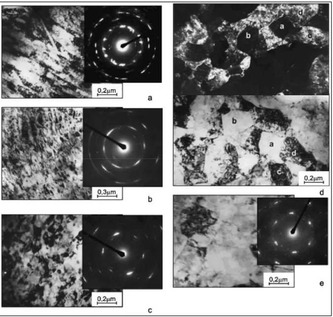
to (a) cold-rolling (e=0.30) and cold rolling with post-deformation annealing at (b) 200oC, (c) 300oC, (d) 350oC and (e) 400oC [73] ...28
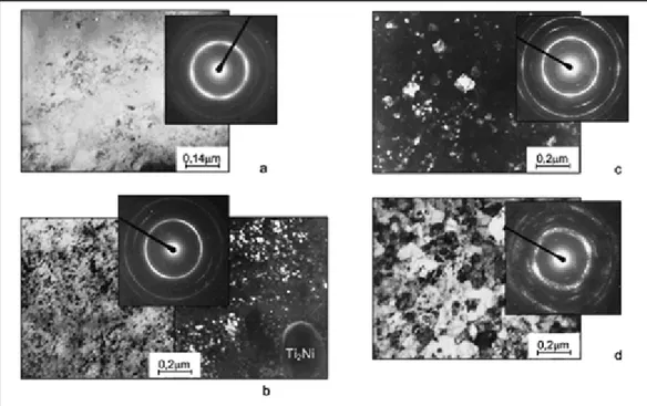
Figure 1.16 Transmission electron microscopy of Ti-50.0at.% Ni alloy subjected to (a) cold-rolling (e=1.9) and cold rolling with post-deformation annealing at (b) 250oC, (c) 300oC and (d) 400oC [73] ...29 Figure 1.17 Transformation temperatures as functions of the PDA temperature for
three levels of cold work (a) e=0.30; (b) e=0.88 and (c) e=1.9 [73] ...30 Figure 1.18 Maxima of recovery stress σr (●) and completely recoverable strain ε
r,1 (0.2% offset) (×) measured as functions of the PDA temperature
after different cold works: (a) e=0.30; (b) e=0.88 and (c) e=1.9 [73] ...30 Figure 1.19 Young’s modulus and strength (a) and plastic elongation and reduction
in area (b) of cold- (solid symbols) and warm- (open symbols) rolled sheets of Ti-24Nb-4Zr-7.9Sn (wt.%) alloy [31] ...31 Figure 2.1 Structure of the Ti-18.3Nb-5.1Zr (TNZ1) alloy after (a) deformation
to e = 0.75 and postdeformation annealing for 1 h at (b, c) 450, (d, e) 600, (f, g) 750, and (h, i) 900°C. Light microscopy ...47 Figure 2.2 Structure of the Ti-19.5Nb-6.5Ta (TNT1) alloy after deformation to
e = 0.3 and postdeformation annealing for 1 h at (a) 700°C (1 h) and
(b) 900°C (30 min). Light microscopy ...48 Figure 2.3 Dependence of the X-ray diffraction line width Bhkl of the β phase on
the degree of initial deformation in the Ti-18.3Nb-5.1Zr (TNZ1) alloy ...49 Figure 2.4 Variation of the width of the X-ray diffraction lines of the β phase of
the Ti-18.3Nb-5.lZr (TNZ1) alloy after deformation to (a) е = 0.28, (b) 0.75, and (c) 2; and (d) the Ti-19.5Nb-6.5Ta (TNT1) alloy after deformation to e = 0.26 and postdeformation annealing. Horizontal lines indicate the levels of Bhkl for the quenched state
(e = 0) (×) 211β, (+) 200β, and (●) 110β ...50 Figure 2.5 The lattice parameter of the β phase in the Ti-21.2Nb-5.6Zr (TNZ2)
alloy after different treatments: (×) e = 0 (quenching at 900°С); (●)
Figure 2.6 Lattice parameters of the α” martensite and the maximum strain of the lattice upon the martensitic transformation of the Ti-19.5Nb-6.5Ta (TNT1) alloy after rolling to e = 0.28, annealing at different
temperatures, and deformation to failure at room temperature ...53 Figure 2.7 Structure of the Ti-21.2Nb-5.6Zr (TNZ2) alloy subjected to moderate
cold deformation (e = 0.28) and postdeformation annealing (1 h) at the temperatures (a) 450, (b) 500, (c) 550, and (d) 600°C. Diffraction electron microscopy: (BF) bright-field images, (DF) dark-field images, and diffraction patterns ...55 Figure 2.8 The structure of the Ti-21.2Nb-5.6Zr (TNZ2) alloy subjected to severe
cold plastic deformation (e = 2) and postdeformation annealing at the temperatures (a) 450, (b) 500, (c) 550, and (d) 600°C. Diffraction electron microscopy: (BF) bright-field images, (DF) dark-field images of the β phase, and diffraction patterns ...56 Figure 2.9 Hardness dependence on the PDA temperature of the alloys: (a)
Ti-18.3Nb-5.1Zr (TNZ1); and (b) Ti-20.9Nb-5.7Zr (TNZ3) ...59 Figure 2.10 Loading-unloading deformation diagrams of the Ti-20.9Nb-5.7Zr
(TNZ3) alloy annealed in the range from 450 to 900°C after moderate plastic deformation (e = 0.37). The inset shows the deformation diagrams of loading-unloading tests at various temperatures after
e = 0.37 and PDA at 600°C ...60
Figure 2.11 Deformation diagrams of loading-unloading of the Ti-19.5Nb-6.5Ta (TNT1) alloy annealed in the range from 450 to 900°C after moderate plastic deformation (e = 0.26) ...61 Figure 2.12 Variation of the microhardness and Young’s modulus of the
Ti-20.9Nb-5.7Zr (TNZ3) alloy depending on the PDA temperature. The initial strain e is 0.37. ...62 Figure 3.1 X-ray diffractograms of Ti-Nb-Ta alloy subjected to CR e=0.37 (a),
e=0.37+PDA (T=500°C, 1h) (b), and e=0.37+PDA (T=750°C, 1h) (c); ↑ - expected locations of ω-phase X-ray lines ...77 Figure 3.2 Structure of Ti-Nb-Ta alloy subjected to CR (e=0.37)+PDA (T=500
(a) and 600°C (b); 1h); a – bright field image, b – dark field image in a β-phase matrix reflection and SAED pattern (<110>β zone axis with
two high-angle misorientations) ...78 Figure 3.3 Dark-field image in ω-phase reflections of Ti-Nb-Ta alloy after CR
corresponding SAED pattern, <110>β zone axis (b, d). Doubled arrow indicates an elongated row of ω particles ...79 Figure 3.4 Microhardness Vickers measurements and stress-strain diagrams of
Ti-Nb-Ta alloy subjected to CR (e=0.37)+PDA (1h) at different
temperatures ...81 Figure 3.5 Microhardness Vickers measurements and stress-strain diagrams of
Ti-Nb-Ta alloy subjected to CR (e=0.37) + PDA (T=500°C, 1h) + AG at 300°C with different aging times (t) ...82 Figure 3.6 Transformation yield stress (σtr) and Young’s modulus of Ti-Nb-Ta
alloy subjected to (a) e=0.37+PDA (1h) at different temperatures, and (b) e=0.37+PDA (T=500°C, 1h) + AG (300°C, 10 min…3h). Insert:
schematic presentation of the transformation yield stress and Young’s modulus measurements ...82 Figure 3.7 Stress-strain cycling diagrams of Ti-Nb-Ta alloys after e=0.37+PDA:
(a) as-deformed, e=0.37; deformed and annealed at 400 (b); 450 (c); 500 (d); 550 (e); 600 (f) and 700°C (g) (all 1h). Aged at 300°C after e=0.37+500°C (1h): 10 min (h); 30 min (i); 1h (j) and 3h (k) ...84 Figure 3.8 Cycling stress-strain diagrams of Ti-Nb-Ta alloys after e=0.37+600°C
at (a) 25°C and (b) 40°C ...85 Figure 3.9 Constant-strain temperature scanning diagrams for 2.5% strain for
Ti-Nb-Ta subjected to e=0.37+PDA (T=450, 500, 600 and 700°C) (a) and e=0.37+500°C (1h) + aging at 300°C (1 and 3 h) (b) ...86 Figure 3.10 Variation of the reverse martensitic transformation temperatures and
characteristic stresses for Ti-Nb-Ta subjected to e=0.37+PDA (a) and e=0.37+500°C (1h) + aging at 300°C (1 and 3 h) (b) ...87 Figure 3.11 Recovery strain dependence on induced strain in bending SM testing
at -196°C and subsequent heating above Af of Ti-Nb-Ta alloy subjected
to CR+PDA (1h) (a) and CR+PDA+AG (300°C, 1h and 3h) (b). To facilitate observation, not all the experimental points are presented ...88 Figure 3.12 Maximum completely recoverable strain of shape memory effect
(εrmax) and number of cycles to failure Nmax after e=0.37+PDA (a) and
e=0.37+500°C (1h)+300°C (t=var) (b) ...91 Figure 4.1 Stress-temperature curves obtained during constant-strain heating of
(adapted from [28, 29]). Shadowed areas indicate the onset
temperatures of the reverse α”→β phase transformation under stress ...98 Figure 4.2 Tensile module for the PANalytical X’Pert Pro diffractometer: a)
schematics of the working principle; b) schedules of the in situ X-ray diffraction temperature scanning experiments: SF – strain-free; SCP – strain-controlled with loading at RT; and SCM – strain-controlled with loading at -150oC [31]...101 Figure 4.3 Tensile strains measured on heating during SCP and SCM experiments
for TNT (a) and TNZ (b) alloys, and tensile loading curves at various recording temperatures for TNT (c) and TNZ (d) alloys. Stress-strain curves (c,d) are obtained in tensile tests similar to [28] ...104 Figure 4.4 Beta-phase lattice parameter temperature dependence for SF (a,b),
SCM and SCP (c,d) experiments for TNT (a,c) and TNZ (b,d) alloys. – – – are the least-squares regressions taken from a) to c) and from b) to d) to facilitate comparison ...105 Figure 4.5 Selected X-ray diffractograms of TNT from SF (a) and SCM (b)
experiments. The experimental positions 1-3 from the SF and 1-4 from the SCM experiments in Figure 4.2b are indicated ...107 Figure 4.6 TNT alloy: X-ray line angular coordinates versus diffractogram
recording temperature from SF (a) and SCM (b) experiments: ● – β-phase, ○ – α”-phase ...108 Figure 4.7 TNT alloy: temperature dependence of the α”-phase LPs and εmax in
SF (a) and in SCM, SCP (b) experiments. The solid lines for aβ, bβ, cβ
and ωβ are brought here from Figure 4.3 ...110
Figure 4.8 Selected X-ray diffractograms of TNZ alloy from (a) SF and (b) SCM experiments. The numbers of the experimental positions 1-3 from the SF and 1-4 from the SCM experiments in Figure 4.2b are indicated ...111 Figure 4.9 TNZ alloy: X-ray line angular coordinates versus diffractogram
recording temperature from SF (a) and SCM (b) experiments: ● – β-phase, ○ – α”-phase, × – ω-phase ...112 Figure 4.10 TNZ alloy: temperature dependence of the α”-phase LPs and εmax
from SF, SCM and SCP experiments: a) calculated using the least squares method and b) calculated directly from the 020α”, 002α” and
200α” line 2θhkl coordinates ...115
Figure 4.11 TNT: Selected X-ray diffraction lines integral intensities versus recording temperature from SF (a) and SCM (b) experiments. The
shadowed areas indicate the starting temperatures of the reverse α”→β transformation ...116 Figure 4.12 TNZ: X-ray diffraction line integral intensities versus recording
temperature from SF (a) and SCM (b) experiments. The shadowed areas indicate starting temperatures of the reverse α”→β and ω→β
transformations ...117 Figure 4.13 Beta-phase X-ray line width versus recording temperature in SF, SCP and SCM experiments for a) TNT and b) TNZ alloys ...118 Figure 4.14 Sequential changes of the 211β peak profile with temperature and
stress in TNZ alloy during SCM (a) and SCP (b) experiments ...120 Figure 4.15 Schematic representation of the critical temperatures of thermoelastic
martensitic transformations under stress. σtr – transformation yield
stress, σcrM – critical stress for martensite reorientation,
σy – dislocation yield stress. 1 – loading, 2 – heating under load ...122
Figure 4.16 Integral intensity of the selected X-ray diffraction lines versus testing temperature from SCM experiment. For comparison, stress as a function of temperature from constant-strain temperature scanning
experiment under εi =1 % induced strain [11] is shown. Shadowed
areas indicate the onset temperatures of the reverse α”→β
LIST OF ABREVIATIONS UTS Ultimate tensile strength
at.% Atomic percent
wt.% Weight percent
bcc Body-centred cubic lattice hcp Hexagonal close-packed lattice ELI Extra-low interstitial alloy(s) SMA Shape memory alloy(s) SME Shape memory effect
Ms Start temperature of the direct martensitic transformation
Mf Finish temperature of the direct martensitic transformation
As Start temperature of the reverse martensitic transformation
Af Finish temperature of the reverse martensitic transformation
TRMT Temperature range of martensitic transformation SE Superelasticity effect
B19' Monoclinic lattice B2 CsCl-type lattice
TMT Thermomechanical treatment
HTMT High-temperature thermomechanical treatment LTMT Low-temperature thermomechanical treatment
CR Cold rolling
PDA Post-deformation annealing AG Ageing
EDM Electrical discharge machining TEM Transmission electron microscopy NSS Nanosubgrained substructure
NCS Nanocrystalline structure
SPD Severe plastic deformation
BF Bright field image
DF Dark field image
SAED Selected area electron diffraction
RT Room temperature
LIST OF SYMBOLS E Young’s modulus Sy Yield stress δ Elongation KI Toughness ΔKth Fatigue threshold Se Endurance limit q Notch sensitivity
e Logarithmic deformation degree
βc Critical minimum level of β-stabilizer content in metastable β Ti-based alloys
βs Minimum level of β-stabilizer content in stable β Ti-based alloys
η Transformation lattice strain among one of lattice parameters σr(σrmax) Recovery stress (maximum recovery stress)
εr(εrmax) Recovery strain (maximum recovery strain)
εr,1 Completely recoverable strain
θ Theta angle in X-ray diffractometry
εmax Crystallographic resource of recoverable strain
σtr Transformation yield stress
Bhkl X-ray peak mid-high width
INTRODUCTION
Nowadays conventional metallic materials for orthopaedic implants have some limitations: pure Ti and conventional Ti-alloys demonstrate limited biomechanical compatibility (elastic behaviour with rather high Young’s modulus), while Ti-Ni-based superelastic alloys are handicapped by their questionable biochemical compatibility related to the presence of toxic nickel in their composition. Thus the search for a new generation of metallic implant materials which would combine biochemical and biomechanical compatibility is still of interest. The most suitable candidates for the role of these new-generation metallic biomaterials are Ti-Nb-based shape memory alloys, especially Ti-Nb-Zr and Ti-Nb-Ta alloys. These alloys contain only biocompatible elements and they manifest superelastic (pseudoelastic) behaviour mimicking that of bone tissue.
In the literature review (Chapter 1), it can be seen from the example of the well-studied Ti-Ni shape memory alloys, that the functional properties of Ti-based shape memory alloys are structure-sensitive, and that their structure and properties can effectively be controlled by thermomechanical treatment. It is also shown that information related to the thermomechanical treatment of Ti-Nb-based shape memory alloys is definitely lacking. Therefore the main objective of this project is to study the interrelations between the composition, the microstructure and the functional properties of superelastic Ti-Nb-Zr(Ta) alloys; and to maximize their functional properties, more specifically the reversible (superelastic) strain and fatigue resistance, through optimization of the alloys’ composition and thermomechanical processing.
The influence of the thermomechanical treatment conditions (including cold rolling, post-deformation annealing and ageing) on the structure of Ti-Nb-based shape memory alloys and, consequently, on their functional properties is investigated in-depth (the first and second articles: Chapters 2, 3). An original tensile stage developed for this project (working principle is described in detail in the Annex) makes it possible to carry out low-temperature
an improved understanding of the phase transformation features of this new family of metallic biomaterials (the third article: Chapter 4). Results obtained are summarized in the Conclusions, and Recommendations are given at the end.
CHAPTER 1
GENERAL INTRODUCTION 1.1 Requirements of metallic implant materials
Metals are widely used as orthopaedic implant materials (parts of hip, knee, ankle, etc. implants), dental fillings, for craniofacial restoration, and in cardiovascular applications. However, not all metals and metallic alloys can be used in medicine because of the special requirements of medical device materials, such as biocompatibility [1],[2]. Generally, metallic implant materials must:
- Be inert in the human body environment (non-toxic, chemically stable and corrosion-resistant) or, in other words, be biocompatible;
- Have mechanical behaviour similar to that of human body tissues and be stable (in some range) during cycling (for example: hip implant should sustain more than 108 of loading/unloading cycles during a lifetime [3]);
- Be straightforward to manufacture;
- Be suitably sterilizable.
1.1.1 Biocompatibility
As mentioned above, biocompatibility implies multiple criteria, the main significance of which can be described by the imperative "do not harm the human body". This means that the implant should be biocompatible at the interface with the human body tissues. This can be realized in three major ways: (1) creation of protective coatings on the implant surfaces (often polymeric), (2) creation of oxide films with a higher biocompatibility than that of the
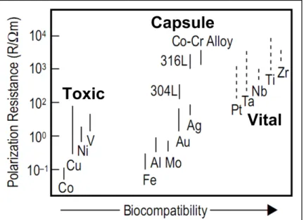
bulk material, and (3) creation of implants from an originally biocompatible compound. The last way is the simplest and the most suitable, since even in the case of surface film damage or when the surface area of the implant is large (the case of porous implants), the implant material will not harm the human body. Figure 1.1 compares the biocompatibility of some metals and metallic alloys. As seen, some alloys have higher biocompatibility than their individual components, which can be attributed to the protective properties of oxide films (stainless steel, for example).
Figure 1.1 The relationship between the polarization resistance and biocompatibility of pure metals, Co-Cr, and
stainless steels [4]
1.1.2 Mechanical behaviour
In the case of bone replacement implants, their mechanical behaviour should be similar to that of human bones (Table 1.1). Mechanical behaviour characteristics include static and dynamic or cycling-depending (fatigue) properties. Static properties can be described by the following parameters: Young’s modulus (E), yield stress (Sy), ultimate tensile strength
(UTS), elongation (δ) and toughness (KI). Fatigue properties are: fatigue threshold (ΔKth),
Table 1.1 Mechanical properties of bones [3],[5]-[12] Property* Value E, GPa 1 – 30 Sy, MPa 15 – 70 UTS, MPa 25 – 150 δ, % 0 – 8 KI, MPa m 2 – 12
* Mechanical properties of bone tissues are not constant because bones consist of different tissues and have self-accommodated structure under external stress conditions.
The static properties are easily determined for an implant material. They present a first step in the selection procedure of a particular implant material. The second step is the fatigue properties. Standard fatigue tests of materials involve load or displacement-controlled cycling.
Mechanical properties are very important criteria for selecting an orthopaedic implant material. For example, the mismatch between the mechanical behaviour of an implant and bone results in “stress shielding” phenomena, bone damage and, consequently, implant loosening [13].
1.1.3 Other requirements
Given the high stability of metallic materials, such requirements as sterilizability (sterilizable by steam, ethylene oxide and gamma rays, for example), and manufacturability to intricate shapes and sizes do not generally require any special precautions. However, in the case of some exotic alloys, there are problems with getting a sufficient quantity of homogeneous material for industrial use.
1.2 Types of metallic implant materials
Metallic materials used for implants can be classified as follows: stainless steels, Co-Cr-based alloys, Ti and titanium alloys, Ag-Sn-Cu (dental amalgams) and pure metals such as Au, Pt, Ta, Zr, etc. [2]. Let us consider the advantages and limitations of the most commonly used orthopaedic implant materials. The major mechanical characteristics of these materials are shown in Table 1.2 and Figure 1.2.
Table 1.2 Mechanical properties of metallic implant materials compared with bones
Material
Property
E, GPa Sy, MPa UTS, MPa δ, % KI, MPa m
Stainless steels (austenitic
316L stainless steels) [5] 210 240 – 800 600 – 1000 55 – 20 ~100
Co-Cr-based alloys [5] 225 525 735 10 ~100
Pure Ta [1],[14] 186 – 191 140 250 20 – 30 –
Pure α-Ti, grade 4 [15] 103 480 550 15 –
Ti-based alloys:
α+β alloys [1],[16] 100 – 110 585 – 860 690 – 930 6 – 15 ~80 β alloys [1],[16] 78 – 84 655 – 908 795 – 137 10 – 22 – Metastable β alloys [1],[16] 55 – 88 736 – 1060 827 – 1100 10 – 22 – Cortical bone [3],[5]-[12] 1 – 30 30 – 70 50 – 150 0 – 8 2 – 12
Figure 1.2 Comparison of mechanical properties of metallic implant materials and bone (from
[1],[3],[5],[14]-[16])
1.2.1 Stainless steel
These ferrous alloys were the first metallic materials used for implant manufacturing. Distinctive features of this class of metallic implant materials are low cost and availability, whereas disadvantages are insufficient corrosion resistance for long-term use and mechanical behaviour, which is far from the behaviour of bone (Figure 1.2). Stainless steels are most frequently used as temporary fixation devices, such as bone plates, intramedullary nails, rods etc. [1].
1.2.2 Co and Co-Cr-based alloys
Cobalt and cobalt alloys were originally used as dental alloys. These alloys have higher corrosion resistance than stainless steel (Figure 1.1), but, according to some literature data, their biocompatibility is still not good enough [16]. The mechanical properties of Co alloys
are similar to the properties of stainless steel and distant from those of bones (Figure 1.2), which complicates their use as bone tissue replacement. Nevertheless, Co-based alloys are widely used as load-bearing components of orthopaedic implants.
1.2.3 Commercially pure Ta
Figure 1.1 shows that Ta is a vital metal. Due to the fact that Ta is inert to the human body, this material is widely used in surgery and neurosurgery as suture wires for skin closure, tendon and nerve repair; as foils and sheets for nerve anastomosis; clips for vessel ligation; and staples for abdominal surgery. Also, due to their low tensile yield stress (Table 1.2), Ta is successfully used as material for cranioplasty plates and reconstructive surgery and for spongy bone tissue replacement [1]. However, this metal has two significant drawbacks: high Young’s modulus (Figure 1.2) and high density (about 16.6 g/cm3, whereas the density of steel is 7.99 g/cm3).
1.2.4 Commercially pure Zr
This metal has excellent resistance to corrosion due a self-healing oxide film formed spontaneously in the air or in the water at ambient temperature. Zr is the most biocompatible of the metals (Figure 1.1), but it is not used in pure form, or as a principal alloying element for orthopaedic implants. This may be due to the high cost of the metal itself and its processing, as well as because of the high anisotropy of its properties [17], although the exact answer to this question is not fully clear. At the moment, this metal is used in the implantology as a component of Ti-based implant alloys or "zirconia" ceramics (zirconium oxide) [1].
1.2.5 Ti and Ti alloys
Titanium is the second best biocompatible metal after zirconium (Figure 1.1). Ti and titanium alloys have low Young’s modulus (about 100 MPa), which is much closer to that of bone
tissue than other metallic implant materials (Figure 1.2). All that makes titanium the benchmark material for orthopaedic implants. Ti-based alloys have even better properties than pure titanium: Young’s modulus of metastable Ti-based alloys can be two times less than that of pure Ti (Table 1.2).
Titanium has two modifications: α (hcp) below 882oC, and β (bcc) above 882oC [18]. Accordingly, titanium alloys may be classified as α, α+β or β depending on their microstructure at test temperature. Their microstructure depends on the type and amount of alloying elements (Figure 1.3). The alloying elements can be divided into three groups: α-stabilizers such as Al, O, N, C; β-α-stabilizers such as Mo, V, Nb, Ta, (isomorphous), Fe, W, Cr, Si, Ni , Co, Mn, H (eutectoid), and neutral, such as Zr or Hf [1],[16]. Also, properties of titanium alloys depend strongly on their phase structure and composition (Table 1.3).
Figure 1.3 Pseudo-binary phase diagram of Ti-β stabilizer [16]: βc – the minimal
content of β-stabilizer for β alloy, βs – the minimal content of β-stabilizer for stable
Table 1.3 Orthopaedic alloys and their mechanical properties [16]
Alloy designation Microstructure E, GPa Sy, MPa UTS, MPa
cpTi Α 105 692 785 Ti-6Al-4V α+β 110 850 – 900 960 – 970 Ti-6Al-7Nb (protasul-100) α+β 105 921 1024 Ti-5Al-2.5Fe α+β 110 914 1033 Ti-0/20Zr-0/20Sn-4/8Nb-2/4Ta+(Pd,N,O) α+β N/A 726 – 990 750 – 1200 Ti-13Nb-13Zr α'+β 79 900 1030
Ti-Zr Cast α'+β N/A N/A 900
Ti-12Mo-6Zr-2Fe (TMZF) Metastable β 74 – 85 1000 – 1060 1060 – 1100 Ti-15Mo-5Zr-3Al Metastable β 75 870 – 968 882 – 975 Aged α+β 88 – 113 1087 – 1284 1099 – 1312 Ti-15Mo-2.8Nb-3Al Metastable β 82 771 812 Aged α+β 100 1215 1310 Ti-15Mo-3Nb-0.3O (21SRx) Metastable β + silicides 82 1020 1020 Ti-35Nb-5Ta-7Zr (TNZT) Metastable β 55 530 590
Ti-35Nb-5Ta-7Zr-0.4O (TNZTO) Metastable β 66 976 1010
Co-Cr-Mo
Austenite(fcc)+ hcp
200 –
230 275 – 1585 600 – 1795 Stainless Steel 316 L Austenite 200 170 – 750 465 – 950
Cortical bone [3],[5]-[12]
Viscoelast.
composite 7 – 30 30 – 70 50 – 150
1.2.5.1 α and near-α titanium alloys
As the name implies, these alloys do not contain β-stabilizers or their quantity is so small (near-α alloys) that the alloys do not leave the α-phase range. The most common alloying elements of α alloys are Al, Sn, and sometimes Zr. These alloys are generally more resistant
to creep at high temperatures than other titanium alloys. Some of these alloys, such as extra-low interstitial α-alloys (ELI grades, Ti-5Al-2.5Sn-ELI, for example [1]) also preserve their toughness at cryogenic temperatures. Thermomechanical processing does not allow strengthening of these alloys, in contrast to α+β and β alloys, so α-alloys are most often used in the annealed or recrystallized conditions (to remove residual stresses induced by cold working) [1].
Near-α alloys, containing a small amount of β-stabilizers (Ti-8Al-1Mo-1V, Ti-6Al-2Nb-1Ta-0.8Mo, for example [1]) are, properly speaking, α+β alloys, but the amount of β phase is so small that it does not influence the alloys’ properties.
Currently, α and near-α titanium alloys are not used as metallic implant materials due to their low strength [1],[16]. In cases where non-load-bearing corrosion-resistant material must be used, commercially pure titanium is preferred to α and near-α alloys [1], because of its higher biocompatibility.
1.2.5.2 α+β titanium alloys
This class of alloys contains both α and stabilizers. Furthermore, since the quantity of β-phase is greater in these alloys, α+β alloys exhibit higher strength than α, near-α alloys and commercially pure Ti (Table 1.3). The properties of α+β alloys depend on the composition and relative proportions of the α and β phases [16].
A two-phase structure of these alloys makes it possible to control their properties by thermomechanical treatment. Alloys are often strengthened by solution treatment and ageing [1]. Solution treatment is usually performed at a high temperature corresponding to the two-phase state and followed by quenching in water. As a result, β-two-phase at the solution treatment temperature may be partially or completely transformed during cooling, due to martensitic transformation. Then, the alloy is aged in a 280 to 650oC temperature range to initiate α-phase precipitation. Ageing produces a fine mixture of α and β α-phases as a replacement of the
β phase remaining after solution treatment. Such a heat treatment can increase the strength of α+β alloys by 30 or 50% [1]. These alloys are widely used for total joint replacement, hip stems, fracture fixation plates, nails, rods, wire, etc.
1.2.5.3 β titanium alloys
As the amount of alloying elements increases, titanium alloys modify their phase structure from α+β to β (after βc, Figure 1.3), i.e. β-phase dominates in the structure after quenching in
water or air cooling.
In turn, β alloys can be divided into metastable β alloys (composition lies between βc and βs,
Figure 1.3) and stable β-alloys (composition above βs). The difference is that stable alloys do
not change their phase composition during thermomechanical treatment, whereas in metastable alloys, phase transformation is possible (precipitation of α-phase or other transformations). Virtually all commercial β alloys are metastable, due to the possibility of phase transformation under external load or temperature variation [1].
Thermomechanical treatment of metastable β alloys implies solution treatment and ageing at 450 – 650oC for the partial transformation of β phase into α phase. The α phase is formed in the initial β-phase as fine particles, which can raise the strength of these alloys to the level of α+β alloys. β alloys have several drawbacks: lower creep strength than that of the α+β alloys and lower ductility in aged conditions. However, despite the low plasticity of β alloys, their fracture toughness is generally higher than that of α+β alloys with the same yield stress [1]. Furthermore, β alloys, before ageing (i.e. when they are composed of only β-phase), have excellent ductility combined with a low yield strength, which provides outstanding formability [1],[16]. From the metallic implant materials standpoint, β alloys possess a unique combination of high corrosion resistance and low Young’s modulus with sufficient ductility (Figure 1.4).
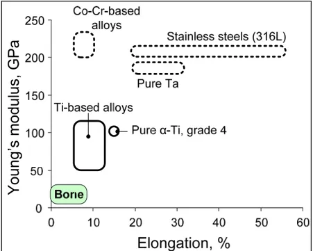
Figure 1.4 Comparison of (a) Young’s modulus and (b) elongation of pure titanium and Ti-based alloys with those of bone (from [1],[3],[5],[15],[16])
1.3 Ti-based shape memory alloys
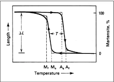
Among metastable titanium β alloys, a special group of these alloys exhibits a shape memory effect (SME) (see Figure 1.5). Generally speaking, shape memory alloys (SMA) are materials that recover their shape due to thermoelastic martensitic phase transformation. This transformation takes place under the influence of external load and/or temperature changes. There are different manifestations of SME: one-way shape memory effect (shape recovery upon heating), two-way shape memory effect (the alloy remembers two shapes, i.e., recovers the shape during both the heating and cooling) and superelasticity (transformation occurs during the alloy deformation at a constant temperature, thereby increasing the range of reversible (quasi-elastic) behaviour. In addition to Ti-based SMA, there are also shape memory alloys based on other metals (Cu, for example) [17],[19].
The following specific parameters are used to describe SMA behaviour: direct martensitic transformation start (Ms) and finish (Mf) temperatures, reverse martensitic transformation
start (As) and finish (Af) temperatures (Figure 1.5), as well as the so-called functional
heating (shape memory effect) or strain recovery during isothermal loading/unloading cycle (superelasticity).
In fact, for bone tissue replacement material, not only the proximity of the basic mechanical characteristics (E, Sy, UTS, δ) to those of bone is important (see Table 1.1 and Figure 1.2),
but also the highly desirable similarity between their behaviour during deformation. As shown in Figure 1.6, in contrast to the majority of metals and metallic alloys, bones have nonlinear elastic behaviour. The behaviour of the superelastic alloy is very different from that of other metallic implant materials being closer to that of bone tissue due to superelasticity and premartensitic lattice softening [20].
Figure 1.5 Typical transformation versus temperature curve for a shape memory alloy specimen under constant
Figure 1.6 Comparison of the stress-strain diagrams of austenitic 316L stainless steel [5], Co-Cr-based alloy [5], pure α-Ti (grade 4) [15], Ti-Ni-based SMA [21] and trabecular bone [22]
Titanium is a very reactive element, so these alloys are melted in vacuum or inert atmosphere. The most frequently used melting methods are plasma-arc, electron-beam and vacuum-induction melting. After melting, an oxide film forms on the alloy surface and it may be subjected to conventional heat treatment [1],[17].
Among all the shape memory alloys, the most common are Ti-Ni-based [1],[19], but these alloys contain toxic nickel, which makes them less suitable for biomedical purposes than the other promising group of SMA – Ni-free Ti-Nb-based alloys. Both groups of alloys will be described in detail in the following section in a comparative manner since they are concurrently contemplated for medical use.
1.3.1 Phase transformation in Ti-based SMA
1.3.1.1 Phase transformation in Ti-Ni-based SMA
Most of the Ti-Ni-based shape memory alloys are binary near-equiatomic alloys (containing 49 – 51at.% Ni) (Figure 1.7), representing the intermetallic compound TiNi. This intermetallic compound is unusual because it has a limited range of solubility of Ti or Ni (Figure 1.7) and a greater ductility than the majority of conventional alloys. The most common alloying is the addition of nickel in the range of 1% in respect of 50at.% Ni.
In addition to the Ti-Ni binary composition, there are many ternary and quaternary Ti-Ni-based alloys. Ternary and quaternary alloys are obtained on the base of Ti-Ni equiatomic alloy, where a part of one component is replaced by the third alloying element or a group of Cu, Al, Fe etc. [24]. Despite the variety of Ti-Ni-based shape memory alloys, only binary alloys are mainly commercially available and widely used [1],[17].
Figure 1.7 Phase diagram of a Ti–Ni alloy, to which the phase equilibrium between the B2 and Ti3Ni4 phases is added [24]
Ti-Ni alloys manifest martensitic transformations like all the SMA and, accordingly, have at least two phases: high-temperature phase and low-temperature phase. The high-temperature phase (austenite) is a B2 (CsCl) type ordered structure [25], and the low-temperature phase (martensite) has a monoclinic lattice (B19') [24]. In addition, martensite may have an orthorhombic lattice B19 in the case of alloying by a third element [26]. There is a possibility of martensitic transformation through an intermediate R-phase with the trigonal lattice structure in the case of nickel supersaturated solid solution [24]. Also, a precipitation of Ti3Ni4, Ti2Ni3 and TiNi3 dispersed particles is possible during ageing (insertion in Figure
1.7). The different types of phase allow martensitic transformation routes (B2→B19', B2→R→B19' and B2→B19→B19' transformations) [24]. The maximum theoretical lattice strain during martensitic transformation is about 11% [19],[27]. Consequently, the maximum recoverable strain is around 8...10%, due to grain misorientation in polycrystalline samples.
1.3.1.2 Phase transformation in Ti-Nb-based SMA
Historically, the minimum concentration of niobium in the Ti-Nb-based SMA is not below 22at.% [28]-[34]. This can be explained by the fact that these alloys are designed primarily as implant materials, where the temperature of the martensitic transformation should be kept around body temperature.
In addition to the binary shape-memory Ti-Nb alloys, there are also ternary and quaternary Ti-Nb-based alloys. As alloying elements, Zr, Ta, Mo, Au, Pd, Pt, Al, Ga, Ge and O are used [35]. Currently, the most promising for medical applications are ternary and quaternary Ti-Nb-Zr, Ti-Nb-Ta and Ti-Nb-Zr-Ta alloys [28]-[31],[35]-[38].
In Ti-Nb alloys, two stable solid-state phases can be observed: high-temperature β-phase (body-centred cubic) and low-temperature α-phase (hexagonal close-packed), as can be seen from the Ti-Nb phase diagram, shown in Figure 1.8 [36]. In this case, the occurrence of martensitic transformation is possible, and high-temperature β phase can be transformed into either α'-martensite (hexagonal) or α"-martensite (orthorhombic) [24]. The maximum lattice
strain during martensitic transformation is about 4% for alloys with niobium content near 22 at.% [39], which is two times lower than that of Ti-Ni alloy.
Besides, low-temperature α-phase can be transformed into ω-phase (hexagonal) [28],[39]. Two types of ω-phase are differentiated: athermal ω-phase (formed during quenching) and isothermal ω-phase (formed during ageing). The interval of the ω-phase formation is approximately 200 – 600oC [39]. The shape memory effect in these alloys is determined by the difference in the lattice parameters of α" and β phases involved in the martensitic transformation [40].
Figure 1.8 Calculated Ti-Nb equilibrium phase diagram [36]
1.3.1.3 Effect of the Ni and Nb contents on the functional properties of Ti-based SMA
In Ti-Ni based SMA, increasing the nickel concentration decreases significantly the martensitic transformation start temperature (Ms) (Figure 1.9) and increases the austenite
yield stress [17],[24]. Consequently, changing the Ni content by 0.1at.% can shift the transformation temperature by 10 – 20 оС [19]. Alloy composition variations affect the alloy properties by changing the phase structure (for example, precipitation of dispersed Ti3Ni4
from the initial austenite [24],[41],[43]) and martensitic transformation sequence.
Figure 1.9 Ms temperature as a function
of Ni content for binary Ti-Ni alloys [24]
For Ti-Nb-based SMA, the start temperature of martensitic transformation and maximum lattice strain during martensitic transformation increase with decreasing niobium content in the range of 15 to 35at.%. (Figure 1.10) [39].
Figure 1.10 Effect of Nb content on the transformation strain (a) and martensitic transformation start temperature (b) [39]
Third elements such as Ta, Zr and O decrease the martensitic transformation temperatures, as shown in Figure 1.11, which should be considered when designing an alloy for medical use. In contrast to the martensitic transformation temperature, the effect of alloying elements on the yield stress and the recoverable strain is not linear, and it is possible to increase the recoverable strain through alloying (for example, Ta in Figure 1.12, [35]).
Figure 1.11 Effect of Ta, Zr and O addition on Ms temperature of Ti-22at.%Nb alloy
Figure 1.12 Influence of Ta content on (a) critical stress for slip (σs) and
apparent yield stress and (b) maximum recovery strain of Ti-22at.%Nb alloy (modified [35])
It should be noted that niobium and tantalum are potent β-stabilizers and effectively decrease the Young’s modulus of Ti alloys [43]-[45]. Zirconium has a similar effect in combination with Nb or Ta [44]; Zr taken alone is not a strong β-stabilizer [1],[16].
Based on [35],[39],[46]-[48], the three main alloy compositions which are the most promising in terms of body-temperature superelasticity can be selected: Ti-22Nb, Ti-22Nb-6Ta and Ti-22Nb-6Zr (Table 1.4).
Table 1.4 Lattice strains (η1, η2 and η3) of
Ti-27Nb, Ti-22Nb-6Zr and Ti-22Nb-6Ta (at.%) alloys [35] Alloy, at.% η1 (%) η2 (%) η3 (%) Ti-22Nb -4.06 4.24 -0.08 Ti-27Nb -2.04 2.55 -0.39 Ti-22Nb-6Ta -2.08 2.46 -0.44 Ti-22Nb-6Zr -2.61 3.37 -0.48
1.3.2 Processing of the Ti-based SMA
The functional properties, as well as the transformation temperature range, not only depend on the chemical composition of the alloy, but are structure-sensitive, which makes it possible to control them by thermomechanical processing (a combination of deformation and heat treatment). The choice of the thermomechanical processing for Ti-based SMA and its parameters may be different depending on the required level of functional properties.
1.3.2.1 Heat treatment
Quenching
Quenching is the heating of an alloy up to the temperature of the austenite recrystallization (700 – 900oC) and subsequent cooling at a sufficient rate to conserve the high-temperature phase at temperatures higher than the martensitic transformation start temperature. This type of treatment is used for alloy softening, for residual stress relaxation, for recovery, homogenization and to prevent diffusion-related transformation during cooling [19].
B2-austenite grains in Ti-Ni do not manifest rapid growth since, when it is heated to 1000oC, the grain size of B2-austenite is less than 50 μm. However, the grain size affects the recovery strain and transformation temperature range. In the case of coarse-grained structures, the resource of recovery strain and transformation temperature range is higher than in the case of fine-grained structures [19].
At the moment, quenching is the most common heat treatment of the Ti-Nb-based SMA. Quenching is generally the reference heat treatment. Thus, most samples are subjected to plastic deformation up to 95%, to post-deformation annealing in the 800 – 1000oC range followed by water-quenching [28]-[31],[33],[39]. After such treatment, despite the high degree of initial strain, recrystallized structure is formed [29]-[31],[33],[49].
Fast cooling is very important in the case of Ti-based SMA because, in these alloys, there may be precipitation of the secondary phase particles (Ti3Ni4 in TiNi or ω- and α-phases in
Ti-Nb alloys) at temperatures below 600oC.
Ageing
Ti-Ni-based SMA are aged in the 250 – 600oC temperature range. Precipitation of the coherent Ti3Ni4 particles is a result of ageing – these particles are oval in shape and their size
is 10 – 100 nm [19]. Precipitation of Ti3Ni4 leads to a change in the composition and
hardening of the initial austenite, which, in turn, affects the functional properties and martensitic transformation temperatures.
Ageing at 250 – 300oC decreases the temperature range of the martensitic transformation, and ageing in the range 300 – 600oC increases the martensitic transformation temperatures [50]-[54]. The initial decrease of TRMT can be explained by accumulation of lattice distortions in the solid solution structure and relaxation of quenching stresses. Ageing at higher temperatures leads to the reduction of nickel concentration in the initial austenite, which increases TRMT (Figure 1.9) [19].
As already mentioned, ageing leads to hardening of the parent phase, i.e. increases the "dislocation yield stress", which leads to enlargement of the difference between the dislocation and the phase yield stresses. Consequently, martensitic transformation can be realized more fully, thereby increasing the value of recoverable strain. The yield stress and ultimate tensile strength of B2-austenite, as well as the consequent maximum recovery stress increase by 5 – 10%, as compared to quenching after ageing of the Ti-50.7at.% Ni alloy at temperatures near 450oC [55]. Ageing in combination with thermomechanical processing can improve the recovery stress and recovery strain [56].
In [30],[34],[37],[39], ageing of quenched Ti-Nb-based SMA in the 200 – 600oC temperature range is performed. With such a heat treatment, dispersed metastable thermal ω-phase and
stable α-phase precipitate. As shown in Figure 1.13, precipitation of these phases strengthens the alloy and increases the UTS and Young’s modulus [57].
Figure 1.13 Variations of the Young’s modulus and ultimate tensile strength of Ti-24Nb-4Zr-7.9Sn (wt.%) alloy as a function of
time of ageing at 500oC [57]
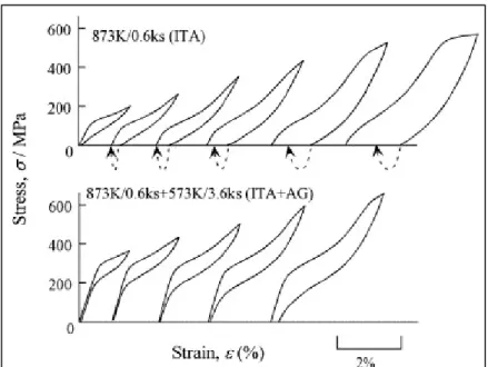
From the superelasticity standpoint, ageing may be an effective way to acquire almost perfect superelasticity at RT of Ti-Nb alloys (Figure 1.14) [39].
Figure 1.14 Stress-strain curves obtained at RT by cyclic loading-unloading tensile tests for the Ti-26at.%Nb alloy
specimen annealed at 873 K for 0.6 ks (intermediate-temperature annealing, ITA) and the specimen aged at 573 K for 3.6 ks after annealing treatment
(intermediate-temperature annealing + ageing, ITA+AG) [39]
Thermal cycling
Thermal cycling is carried out through the interval of the martensitic transformation, i.e. direct and reverse martensitic transformations repeatedly occur in the alloy. Thermal cycling may be performed both in stress-free conditions and under applied external stress. Stress-free thermal cycling leads to the strengthening of the initial austenite due to multiple transformation-induced phase hardening [58], while thermal cycling under load creates oriented dislocation substructure and oriented stress fields in the Ti-based SMA [59]-[62]. Both these treatments are commonly used for stabilization of the functional properties and the martensitic transformation temperatures prior to their practical use [19],[63]-[66].
1.3.2.2 Thermomechanical treatment
Thermomechanical treatment involves deformation and thermal treatment which can be carried out simultaneously or sequentially. Historically, thermomechanical treatments have been divided into two types: high-temperature thermomechanical treatments (HTMT) and low-temperature thermomechanical treatments (LTMT). The line between these two types of thermomechanical treatment is conditional and corresponds to 0.5 of the melting point temperature (in Kelvin).
High-temperature thermomechanical treatment
High-temperature heat treatment (HTMT) of Ti-Ni-based shape memory alloys is conducted in the 500 – 1000oC temperature range [19]. Processes of deformation strengthening and softening develop simultaneously during this type of treatment [67]. Consequently, a wide range of structures can be created: from so-called "hot-worked" substructure with a high density of dislocations (more than 1010 cm-2) to fully recrystallized structure [68],[69]. However, HTMT is mostly used for the shaping of materials without causing significant changes in their crystalline structure and functional properties.
For Ti-Nb SMA, in some works [38],[57], HTMT at 800oC is used as a preparation technique prior to the main thermomechanical treatment.
Low-temperature thermomechanical treatment
Low-temperature thermomechanical treatment (LTMT) consists of the alloy’s deformation at temperatures below the beginning of the recrystallization of the parent phase. It should be noted that the deformation may take place in the temperature range corresponding to martensite, or martensite can be induced and deformed during deformation [19],[70],[71].
LTMT can stabilize and significantly improve SMA properties, such as recovery stress and recovery strain, through the creation of a wide range of dislocation substructures and grain structures [19].
Ti-Ni-based SMA
LTMT is the best studied thermomechanical treatment for TiNi SMA, due to its capacity to regulate the functional properties and temperatures of the martensitic transformation of this material.
Plastic deformation by cold rolling (CR) with e = 0.3 – 2 is most common for Ti-Ni-based SMA, because deformation lower than e = 0.3 is not enough to induce significant structural changes [72],[73], and deformation higher than e =2 can lead to destruction of samples [19]. Let us consider next the impact of different degrees of deformation on the structure and properties of the alloy: the moderate (e≈0.3) and severe (e≈2) deformations.
Moderate plastic deformation (e=0.3) leads to the formation of a well-developed dislocation substructure in martensite (Figure 1.15a). The post-deformation annealing of the cold-worked material causes the reverse martensitic transformation and material softening. When the annealing temperature increases, static recovery and polygonization (formation of subgrain boundaries) occur (Figure 1.15b-e) [74],[75]. With a further increase of annealing temperature, the process of recrystallization and subsequent grain growth will take place. The growth of subgrains is observed in the 200 – 400oC temperature range. Consequently, after 300oC, there is polygonized nanosubstructure, whereas after 400oC, the subgrain size is about 300 – 500 nm [74].
After severe plastic deformation (e=2), mixed nanocrystalline and amorphous structures are formed; the size of the nanograins is about 2 – 8 nm (Figure 1.16a) [74]. Annealing at 300oC forms nanostructure with 5 – 20 nm grain size (Figure 1.16b) [74]. Temperature increase leads to the subsequent grain growth (Figure 1.16c, d). It is impossible to notice any
difference in the structure regardless of the degree of the initial strain, after annealing at 700oC [19],[74].
Figure 1.15 Transmission electron microscopy of Ti-50.0at.% Ni alloy subjected to (a) cold-rolling (e=0.30) and cold rolling with post-deformation annealing at (b) 200oC, (c)
Figure 1.16 Transmission electron microscopy of Ti-50.0at.% Ni alloy subjected to (a) cold-rolling (e=1.9) and cold rolling with post-deformation
annealing at (b) 250oC, (c) 300oC and (d) 400oC [74]
As shown in Figure 1.17 and Figure 1.18, thermomechanical treatments significantly affect the functional properties of Ti-Ni SMA. The temperature of martensitic transformation decreases with an increase in the density of defects (Figure 1.17). Additionally, nanocrystalline and amorphous structures lead to a significant reduction in the temperature of martensitic transformation (Figure 1.17c) compared with the polygonization substructure (Figure 1.17a). It should be noted that grain refinement less than a certain size (25 nm) makes the martensitic transformation impossible, according to [76]. With a refining of the structure or substructure in the nanoscale region, the improvement of functional properties is obtained (Figure 1.18). In the case of the nanocrystalline structure, there is a maximum of functional properties: reversible strain is 8%, and recovery stress reaches 1400 MPa, which is 3 – 4 times higher than for the quenched sample [19],[74],[77].
Figure 1.17 Transformation temperatures as functions of the PDA temperature for three levels of cold work (a) e=0.30; (b) e=0.88 and (c) e=1.9 [74]
Figure 1.18 Maxima of recovery stress σr (●) and completely recoverable strain εr,1 (0.2%
offset) (×) measured as functions of the PDA temperature after different cold works: (a) e=0.30; (b) e=0.88 and (c) e=1.9 [74]
Ti-Nb-based SMA
The influence of cold and warm deformation on the basic mechanical properties of Ti-Nb-based SMA was exclusively studied [32]. Cold deformation of Ti-Nb-Ti-Nb-based alloys leads to the formation of nanocrystalline structure and the precipitation of a large number of α"-phase in the β-phase particles and results in alloy brittleness [32]. Warm deformation at 200oC allows the α"-phase precipitation phenomenon and reduction of the alloy’s brittleness to be avoided, as shown in Figure 1.19 [32]. Regardless of the deformation temperature, increasing the degree of deformation increases the strength and decreases the plasticity and the recoverable strain. The positive effect of this treatment is the decrease of Young’s modulus (Figure 1.19a).
Figure 1.19 Young’s modulus and strength (a) and plastic elongation and reduction in area (b) of cold- (solid symbols) and warm-
(open symbols) rolled sheets of Ti-24Nb-4Zr-7.9Sn (wt.%) alloy [32]
As seen from the literature analysis, knowledge of the Ti-Nb-based SMA thermomechanical treatment was quite limited at the time of the beginning of the current work. For example, we were not able to find any comprehensive information about the influence of LTMT on the crystalline and phase structure, lattice parameters and functional properties of Ti-Nb-based SMA.
1.4 Research objectives
Despite having lower recovery strain than compared to Ti-Ni SMA, Ti-Nb-based SMA have a very important advantage from the medical applications standpoint. They are Ni-free and may consist of non-toxic alloying elements only. It is known from the literary sources that the functional properties of these alloys are structure-sensitive. Consequently, their functional properties can be controlled by thermomechanical treatment. However, there is not enough information about the effects that thermomechanical treatment has on the functional properties of these alloys. The objectives of my Ph.D. project are therefore:
• To study the interrelations between the composition, microstructure and functional properties of superelastic Ti-Nb-Zr(Ta) alloys;
• To maximize the functional properties of Ti-Nb-Zr(Ta) alloys, more specifically superelastic strain and fatigue resistance, through optimization of their composition and thermomechanical processing conditions.
1.5 Methodology
The methodology used in this work is presented in detail in each article (Chapters 2-5). However, a brief overview of the materials, thermomechanical treatments and characterization techniques used in this work is presented below for better understanding.
1.5.1 Materials
Ti-Nb-based alloys with compositions close to the target (Ti-22Nb-6Zr and Ti-22Nb-6Ta, at.%) are as follows: Ti-Nb-Ta small-weight ingots (about 250 g) cast in GIREDMET (Russia), while Ti-Nb-Ta and Ti-Nb-Zr large-weight ingots (about 7 kg) produced in
TSNIICHERMET (Russia) and Flowserve Corp. (USA) correspondingly. Then the ingots are
EDM-cut into samples and subjected to thermomechanical treatment. It should be noted that such large-weight ingots of the experimental Ti-Nb-Ta and Ti-Nb-Zr SMA have been obtained for the first time in this work.
1.5.2 Thermomechanical treatment
Based on the literature data, thermomechanical treatment consisted of cold rolling and subsequent thermal treatment such as annealing or/and ageing.
Cold rolling is performed on a FENN four-high rolling mill at room temperature with the
e=0.3 – 2 deformation range. There are no significant changes in the alloy’s structure below this range of deformation; above this range, the material fractures.
Annealing is conducted in a PYRADIA laboratory furnace in air. The annealing temperature is
varied in the 450 – 900oC range. There are active processes of ω- and α-phase precipitation at temperatures below this range, which is not suitable. The structure is fully recrystallized after annealing at 900oC, and further temperature increase serves no purpose. The alloy is
quenched in water after annealing, to prevent precipitation of the isothermal brittle ω-phase.
![Figure 1.6 Comparison of the stress-strain diagrams of austenitic 316L stainless steel [5], Co-Cr-based alloy [5], pure α-Ti (grade 4) [15], Ti-Ni-based SMA [21] and trabecular bone [22]](https://thumb-eu.123doks.com/thumbv2/123doknet/7443269.220792/39.918.321.684.164.611/figure-comparison-stress-strain-diagrams-austenitic-stainless-trabecular.webp)
![Figure 1.7 Phase diagram of a Ti–Ni alloy, to which the phase equilibrium between the B2 and Ti 3 Ni 4 phases is added [24]](https://thumb-eu.123doks.com/thumbv2/123doknet/7443269.220792/40.918.170.670.669.1042/figure-phase-diagram-alloy-phase-equilibrium-phases-added.webp)

![Figure 1.17 Transformation temperatures as functions of the PDA temperature for three levels of cold work (a) e=0.30; (b) e=0.88 and (c) e=1.9 [74]](https://thumb-eu.123doks.com/thumbv2/123doknet/7443269.220792/54.918.112.728.160.566/figure-transformation-temperatures-functions-pda-temperature-levels-cold.webp)
