Building on Our Growth Opportunities May 27 – 30, 2015
Miser sur nos opportunités de croissance REGINA, SK
SIMPLIFIED DESIGN METHOD FOR ENERGY DISSIPATING DEVICES
IN RETROFITTING OF SEISMICALLY ISOLATED BRIDGES
Seyyed Behnam Golzan1, Sébastien Langlois1, Eng., Ph.D and Frédéric Légeron2, Eng., Ph.D
1
Department of Civil Engineering, Université de Sherbrooke, Sherbrooke, Qc, Canada
2
Parsons, Abu Dhabi, United Arab Emirates
ABSTRACT
This paper presents an innovative simplified method for the optimum design of seismically isolated bridges incorporating energy dissipating devices. For an isolated bridge subjected to an earthquake, the deformation is concentrated in the isolators, which greatly reduces the seismic base shears transmitted from the superstructure to the substructures. However, some factors such as space limitations, stability requirement etc. limit the allowable deformation taking place across an isolator. To control the deformation of the isolators, supplemental energy dissipating devices can be introduced into the isolation system. This may nevertheless increase the total structure base shear and the merit of adding dampers has to be evaluated properly. In this study, a simplified approach is developed in order to optimize the performance of the isolated structure. This method is based on a simplification of the system and by setting objectives for displacement reduction as well as acceptable base shear increase. Based on this approach, damper stiffness and damping is determined as a function of pier and isolator stiffness. The method provides a range of added stiffness and damping that will be needed to reduce the total displacement of the structure while controlling the increased structural base shear. To verify the robustness of the method, response spectrum analysis of a typical isolated bridge has been performed. The numerical simulations showed a close relation with the proposed simplified method. It is concluded that the proposed simplified approach has the potential to optimize the performance of isolated bridges incorporating energy dissipating devices.
Keywords: Isolated Bridge, Energy Dissipation Device, Seismic Loading, Structural system, Response
Spectrum Analysis.
1. INTRODUCTION
Seismic isolation of bridge structures is becoming increasingly a requirement in the field of structural engineering as it offers better behavior in comparison with some non-isolated structures subjected to earthquake loads. Golzan and Légeron (2010) did a parametric research on the admissibility of base isolation for highway bridges based on CSA-S6-06 and found out that it is very interesting to use an isolation system for lifeline bridges with 7.5% probability of exceedance in 75 years. Even for an emergency bridge, in most cases, they found that isolation system is interesting to reduce the total base shear on the substructure. This is generally true on sites with rock or very stiff soils and very stiff substructure composition (Thakkar and Maheshwari, 1995). Modeling of isolating devices might not be any easy task and a progressive refinement of the structural model should be adopted in order to simplify the design process. Seismic isolation design is for reducing the ductility demand on the substructures by adding such flexible devices that add known and tested rigidity and damping to the structure. Isolated structures however, may experience large displacements which in certain cases reduce the interest of using isolation, especially for small to medium span typical bridges where expansion joints and clearances may result in significant increase of initial and maintenance cost. In this case, it would be interesting to provide supplemental damping to reduce the displacement demand. However, supplemental damping can increase seismic loads in certain cases (Jangid and Kelly, 2001). For example Kelly (1999) has pointed out that the extra viscous dampers may increase significantly the higher-mode response in the structures. For this, two issues in the choice of optimal damping are concerned; first the optimal distribution of the supplemental damping and second, the optimal mechanical properties of
when this configuration gives the highest damping ratio of the fundamental mode of the structure which contributes more to the total response of the structure (Ashour and Hanson, 1987).
Robinson (1982) and Skinner et al. (1993) showed that one method for augmenting energy dissipation of for example laminated rubber bearings, is to supplement external components such as lead plugs inserted in the bearing. Other added damping devices such as hysteretic or viscous dampers have also been proposed to substitute lead plugs (Parducci and Mezzi 1991; Cousins et al. 1991).
The procedure for designing a supplementary energy dissipating device for an isolated bridge can be split in three steps. The first step is to assess the performance of the structure, which is just isolated or isolated and damped, in terms of base shear and superstructure displacement as well as to identify its fundamental period and damping level. The second step is to use an analytical or numerical method to identify targets for the final base shear and displacement and calculate adequate values for the period and damping of the structure. The last step of the procedure is to design or select an energy dissipation device that matches the required properties to obtain an efficient and economic retrofit of the bridge. This paper concerns mostly the second step of the procedure.
The objective of this research is to provide a simplified method to refine the choice of optimized damper elements in combination with the isolation system. They work together for a proper behavior of the bridge structure. An optimum point is where the combined system provides a proportional value of base shear and displacement in the structure at the modified frequency after introducing the damping system. The method could be applied in the design of new bridges or in the assessment and retrofit of the existing ones. It is believed that with simple adjustment the method could be adapted to any code. A typical two-span seismically-isolated highway bridge is considered in this study. The bridge is analyzed for eleven cases of damper stiffness and damping level. Having the base shear and superstructure displacement of a given bridge, the simplified method could be applied to define a damping system that will yield a new desired behavior of the structure in terms of base shear and superstructure displacement. Finally, the proposed damper design is compared to the results from response spectrum analysis method, which shows the efficiency of the developed method for the evaluation of optimal damper in isolated bridges.
2. MATHEMATICAL DEVELOPMENT
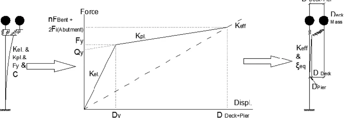
Seismic isolators in conjunction with passive energy dissipaters are assumed as typical paraseismic systems. Although it is more accurate to obtain maximum displacement demand through time-history analysis, in most cases simple linear response spectra or uniform hazard elastic response spectra can be used at least for preliminary sizing of isolation system. These methods are based on equivalent linearization of the system by using an effective lateral stiffness and equivalent damping ratio as shown in Figure 1. As shown in these figures, a bridge deck supported on the substructure through an isolation system along with any additional devices for energy dissipating purposes could be simply taken as a single-degree-of-freedom model with effective stiffness and damping. Equivalent linear models have been incorporated in AASHTO (2010), Eurocode 8 (2005) and CSA-S6-06, among other specifications, for designing bridges with passive energy dissipation systems.
To obtain the effective stiffness Keff and equivalent damping of a hysteretic system ξeq, three parameters
of elastic stiffness (Kel), hardening ratio (α= Kel / Kpl) and ductility ratio (μ=D/Dy) are taken as variables and
are set to desirable values.
For a specific damping ratio of a structure the design spectra and accelerograms change. This is shown by referring to Equation 1 of coefficient of elastic response of isolated structures in CSA-S6-06:
[1] C′sm= ASi BTe
Where A is the zonal acceleration ratio, Si is the site coefficient for isolated structures and Te from
Equation 2 is the damped natural period of vibration of a SDOF system with a mass m and damping coefficient 𝝃eq (Priestley et al. 1996).
[2] Te= 2π√ m Keff(1 − ξeq2)
The damping reduction factor is calculated for values of ξeq≥ 0.02 by Equation 3 (AASHTO 2010):
[3] 𝐵 = (𝜉𝑒𝑞 0.05)
0.3
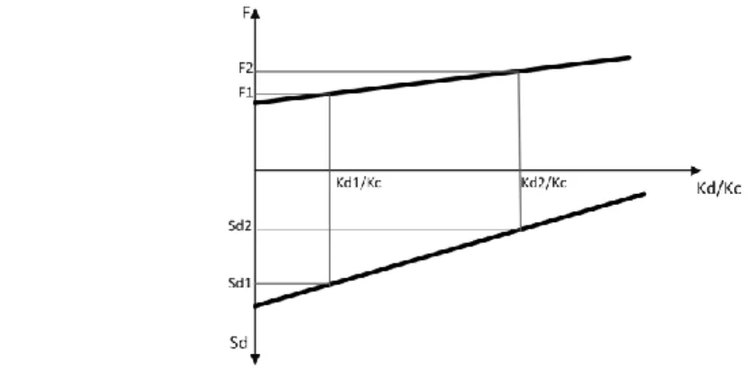
An appropriate value of B shall be chosen so it reduces the base shear demand more than the increase resulting from the stiffening of the structure. It shall be ideal that, when adding damping to an isolated structure, the increase rate of base shear on the substructure is lower than the rate of decrease of superstructure displacement. Figure 2 shows the targeted variation of superstructure displacement, Sd
and the base shear, F on a bridge structure as the normalized ratio of damper stiffness to substructure stiffness increases.
Figure 2 : Conceptual variation of base shear and displacement versus variation in dampers’ stiffness normalized with substructure stiffness
By adjusting damping reduction coefficient, B, assuming Equation 1, the necessary condition for simultaneous increase of base shear and decrease of displacement will be:
[4]Te1
Te2> B2 B1
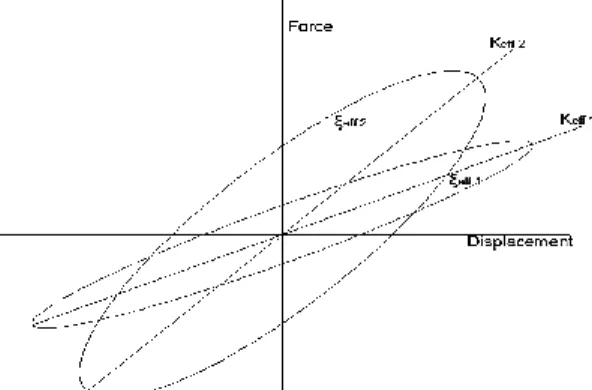
Figure 3 shows the main concept taken in this paper to design damper for bridge structures. The first position is where the structure is in terms of stiffness and damping. The goal is to attain the second position by adding stiffness and sufficient damping to the structure and arrive at a point with desired lower superstructure displacement and desired increase in the base shear.
Figure 3: Initial and target equivalent system for desired base shear and displacement
To change the inequality in Equation 4 into equality considering Figure 3 and by developing a mathematical procedure we can attain Equation 5 as another relationship between the period and the damping in the structure. Equations 4& 5show that, the proportion of damping reduction coefficients has a narrow range. [5] Te2 Te1 = B1 (1 + ε)B2= √ 1 − 𝜑 1 + 𝜀 < 1 Where:
ε, is the rate of variation of base shear relative to the initial base shear 𝜑, is the rate of variation of displacement relative to the initial displacement
Considering Equation 5 and relating it to the proportion of effective stiffness of the structure we will have:
[6] Keff2 Keff1 = ( Te1 Te2) 2 =(1 − 𝜑)(1 + 𝜀)
2.1 Obtaining target stiffness and equivalent damping ratio of dampers
In bridge structures the isolation system is placed on abutments (Supports at both extremities) and bents (Supports in between the abutments). They behave in series with bents while they are in parallel condition with the damping elements on the bents. More specifically, introducing the effective stiffness of all bearing segments, substructure, isolation system and energy dissipating system in the initial condition with zero or little known damping and in the second condition with added damping of the structure we can rearrange Equation 6 into Equation 7.
[7] Keff2 Keff1 = Ki (abutments)+ (Kd2(1)+Ki (Bent)(1))Kc 1 (Kd2(1)+Ki (Bent)(1)+Kc 1 +…+(Kd2(m)+Ki (Bent)(m))Kc m (Kd2(m)+Ki (Bent)(m)+Kc m Ki (abutments)+ (Kd1(1)+Ki (Bent)(1))Kc 1 Kd1(1)+Ki (Bent)(1)+Kc 1+…+ (Kd1(m)+Ki (Bent)(m))Kc m Kd1(m)+Ki (Bent)(m)+Kc m =1+ε 1-φ Where:
Ki (abutments) is the total stiffness of designed isolators on the abutments Ki (Bent) is the total stiffness of designed isolators on each bent
Kc 1~Kcm is the stiffness of each bent from 1 to m in the substructure
Kd2 is the total effective stiffness of dampers on each bent after adding damper
Kd1 is the initial total effective stiffness of dampers on each bent which could be taken as zero for
non-damped structures
Keff1 and Keff2are the initial and final effective stiffness of the whole structure
Assuming a uniform distribution of dampers on all bents represented initially by Kd1 (which could also be
zero) the damper stiffness in the target distribution of dampers represented by Kd2 could be calculated
from Equation 7.
Considering Equation 5 the ratio of damping reduction factor before and after retrofit is obtained and since the initial properties of the structure (frequency, damping ratio and effective stiffness) are known, the damping reduction factor of the whole structure in the target situation shall be simply calculated from the same equation. Using Equation 3, the damping ratio, ξeq2, can also be readily obtained. The equivalent
damping ratio of a two span bridge structure could be obtained from Equation 10.
[10] 𝜉𝑒𝑞= 𝐾𝑖(𝐴𝑏𝑢𝑡𝑚𝑒𝑛𝑡) 𝐾𝑒𝑓𝑓 𝜉𝑖+ 𝐾𝐵𝑒𝑛𝑡 𝐾𝑒𝑓𝑓 [ 𝐾𝐵𝑒𝑛𝑡 𝐾𝑐 𝜉𝑐+ 𝐾𝐵𝑒𝑛𝑡 𝐾𝑖(𝐵𝑒𝑛𝑡)+ 𝐾𝑑( 𝐾𝑖(𝐵𝑒𝑛𝑡) 𝐾𝑖(𝐵𝑒𝑛𝑡)+ 𝐾𝑑𝜉𝑖+ 𝐾𝑑 𝐾𝑖(𝐵𝑒𝑛𝑡)+ 𝐾𝑑𝜉𝑑)] Where:
ξeq is the equivalent damping ratio of the two span bridge structure which is known based on this study.
ξc is the damping ratio of the substructure and soil which is normally taken 5%.
ξi(Abutment) is the damping ratio of the isolation system on the abutment which is known form the isolation system design.
ξi(Bent) is the damping ratio of the isolation system on the bent which is known form the isolation system design.
ξd is the damping ratio of the dampers.
In Equation 10 all parameters except ξd2 are known from the method developed in this study which leads
to calculate the value of damping ratio of the dampers in the target situation of the structure, ξd2.
Employing this method the relation between the effective stiffness and the equivalent viscous damping of the energy dissipating system before and after retrofitting could be calculated. An already isolated or isolated-damped bridge structure is characterized by its frequency of vibration, stiffness and damping which yield the total base shear on the substructure as well as the displacements on the superstructure.
3. BRIDGE MODEL
In this section a typical two-span highway bridge has been modeled with eleven scenarios for added dampers: one case with only isolation system and ten cases with isolation and increased values of stiffness and damping through the added dampers (Figure 4).
Figure 4 Typical two-Span isolated-damped bridge analysis model (span length=35m, pier height=6.8m)
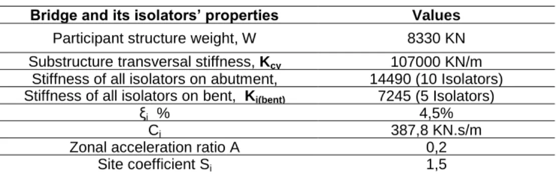
This base isolated bridge has already been designed for vertical dead and traffic loads based on the uniform load method and the direct displacement method. The isolation design issues are not discussed in this paper. All assumptions from CSA-S6-06 and the isolation system properties are outlined in Table 1.
Table 1: Design assumptions and the isolation system properties
Bridge and its isolators’ properties Values
Participant structure weight, W 8330 KN
Substructure transversal stiffness, Kcy 107000 KN/m Stiffness of all isolators on abutment,
Ki(abutment)
14490 (10 Isolators) Stiffness of all isolators on bent, Ki(bent) 7245 (5 Isolators)
ξi % 4,5%
Ci 387,8 KN.s/m
Zonal acceleration ratio A 0,2
Site coefficient Si 1,5
Having designed the required isolation system, the displacement of the superstructure is determined to be 96 mm by analysis. Assuming the proposed simplified method the displacement could be reduced to the desired value by adding damper to the structure at the cost of some increase in the base shear. Based on the proposed method and from Equation 5, first the period of the structure at the desired reduced superstructure displacement and acceptable increased base shear could be determined. In the second step from Equation 6 the effective stiffness of the structure, Keff2, is calculated. The equivalent
damping ratio of the structure after adding damper, B2, is calculated from Equation 5. For a two span
regular bridge the effective stiffness of the damper and its damping coefficient at both transversal and longitudinal directions of the structure then shall be calculated form Equations 11& 12.
[11] 𝐾𝑑=𝐾𝑐𝐾𝑖 𝐵𝑒𝑛𝑡− 𝐾𝑒𝑓𝑓𝐾𝑐− 𝐾𝑒𝑓𝑓𝐾𝑖 𝐵𝑒𝑛𝑡+ 𝐾𝑖 𝐴𝑏𝑢𝑡𝑚𝑒𝑛𝑡𝐾𝑐+ 𝐾𝑖 𝐵𝑒𝑛𝑡𝐾𝑖 𝐴𝑏𝑢𝑡𝑚𝑒𝑛𝑡 𝐾𝑒𝑓𝑓− 𝐾𝑖 𝐴𝑏𝑢𝑡𝑚𝑒𝑛𝑡− 𝐾𝑐 [12] 𝜉𝑑= [ [ [ 𝜉𝑒𝑞− (𝐾𝑖 𝐴𝑏𝑢𝑡𝑚𝑒𝑛𝑡𝐾 𝑒𝑓𝑓 ) 𝜉𝑖 𝐾𝐵𝑒𝑛𝑡 𝐾𝑒𝑓𝑓 ] − (𝐾𝐵𝑒𝑛𝑡 𝐾𝑐 ) 𝜉𝑐 ] 𝐾𝐵𝑒𝑛𝑡 𝐾𝑖 𝐵𝑒𝑛𝑡+ 𝐾𝑑 ] − ( 𝐾𝑖 𝐵𝑒𝑛𝑡 𝐾𝑖 𝐵𝑒𝑛𝑡+ 𝐾𝑑) 𝜉𝑖 𝐾𝑑 𝐾𝑖 𝐵𝑒𝑛𝑡+ 𝐾𝑑
4. RESPONSE SPECTRUM ANALYSIS
The structure has been analysed by response spectrum method to provide a comparison to the results taken from the simplified method. For response spectrum analyses the spectrum from code CSA-S6-06 has been taken based on the site properties in Table 1.
To model the isolation system, a biaxial hysteretic link element has been employed with its linear properties for all deformations. For the analysis the effective values of stiffness and damping in both longitudinal and transversal directions of the bridge have been introduced to the isolators and the dampers. The damper elements are not supposed to undergo vertical loading and the whole load is taken by the isolators. Definition of linear characteristics for dampers follows the same principles as for the isolator elements. Although, strictly speaking, modal analysis is not applicable to nonclassically damped systems, it can provide results that suffice for the objective of approximate solution. Because of nonclassical damping, the coupling terms of the damping matrix are nonzero and the modal equations are coupled and the approximation in using classical modal analysis for a system is done by neglecting the coupling effects [Chopra]. In response-spectrum analysis the effective damping values are converted to modal damping ratios assuming proportional damping where the modal cross-coupling damping terms are ignored. These effective modal-damping values are added to any other modal damping that is specified directly. Considering the aforementioned typical two-span bridge with a known isolation system design, the values of stiffness and damping for the dampers have been taken in an increasing manner. Table 2 shows the primary calculated effective properties of the dampers. The damper characteristics have been taken such that the effective stiffness starts from around 1% of the stiffness of the substructure in the transversal direction. The finite element model has a transversal stiffness of Kcy=107000 KN/m. For
practical reasons the ratio of damper to substructure stiffness has been limited to 29%.
Table 2: Assumed effective damper properties
Kd KN/m ξd Kd/Kc Case 0 - - - Case 1 1034 0.21 0.01 Case 2 5415 0.22 0.05 Case 3 9444 0.23 0.09 Case 4 13121 0.24 0.12 Case 5 16445 0.26 0.15 Case 6 19418 0.27 0.18 Case 7 22039 0.29 0.21 Case 8 24307 0.31 0.23 Case 9 26223 0.33 0.25 Case 10 30800 0.35 0.29
The damping ratio of the damper, ξd , was assumed to increase with the damper effective stiffness, Kd, to
be consistent with a bilinear behavior of the damper. Case 0 represents the case that there is no added damper introduced to the structure.
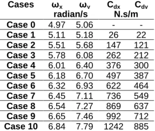
By introducing the damper effective stiffness to the finite element model the undamped structure’s frequency, ωe, in both longitudinal and transversal directions is determined. These two directions are attributed to two principal periods of the structure respectively; then the damping coefficient of the dampers, Cd in both directions using the supported superstructure horizontal mass by all dampers and ωe
is calculated. The damping coefficients as outlined in Table 3 are applied to the model for a response spectrum analysis through which the values of base shear and deck displacement could be calculated.
Cases ωx ωy Cdx Cdy radian/s N.s/m Case 0 4.97 5.06 - - Case 1 5.11 5.18 26 22 Case 2 5.51 5.68 147 121 Case 3 5.78 6.08 262 212 Case 4 6.01 6.40 376 300 Case 5 6.18 6.70 497 387 Case 6 6.32 6.93 622 464 Case 7 6.45 7.11 736 549 Case 8 6.54 7.27 869 637 Case 9 6.65 7.46 992 712 Case 10 6.84 7.79 1242 885
The damping coefficients of the dampers are then adjusted to the frequency in principal directions. Deck displacements and base shear values in the structure are outlined in Table 4. DD is the deck displacement and PD is the pier maximum displacement. F is the base shear due to seismic loading.
Table 4: Longitudinal and transversal displacement and force from spectrum analysis
Adjusted in longitudinal direction Adjusted in transversal direction DDx DDy PDx PDy Fx Fy DDx DDy PDx PDy Fx Fy mm KN mm KN Case 0 82.1 80 17.8 5 1664 1641 82.1 80 17.8 5 1664 1641 Case 1 79.8 76.4 18.9 5.3 1667 1640 79.8 76.4 18.9 5.3 1667 1640 Case 2 72.8 65.2 22.6 6.6 1697 1655 73.1 65.6 22.7 6.7 1704 1665 Case 3 68.9 58.4 25.3 7.6 1731 1681 69.4 59.1 25.5 7.7 1744 1701 Case 4 66.4 53.8 27.3 8.3 1762 1705 67.1 54.7 27.5 8.4 1780 1734 Case 5 64.6 50.4 28.7 8.8 1785 1722 65.4 51.5 29.1 9 1808 1759 Case 6 63.2 47.7 29.8 9.2 1802 1733 64.2 48.9 30.3 9.4 1829 1779 Case 7 62 45.5 30.6 9.4 1813 1736 63.1 46.9 31.2 9.7 1844 1789 Case 8 61 43.7 31.2 9.6 1818 1732 62.2 45.2 31.8 9.9 1853 1793 Case 9 60.1 42.1 31.6 9.7 1817 1722 61.5 43.7 32.2 10.1 1856 1789 Case 10 58.9 39.5 32.6 10 1835 1731 60.4 41.3 33.4 10.5 1880 1810
The deck displacement along with the bridge base shear is plotted versus the ratio of dampers stiffness to substructure lateral and greater stiffness. In Figure 5 increase and decrease rates of both parameters in two directions of the structure are seen which shows milder increase in base shear than decrease in the displacement.
To implement the simplified method on the same structure, we need to calculate the variation rate in base shear and deck displacement of the structure in a way that the desired values of base shear and displacement are attained. The simplified method is based on the difference between the damping ratio before and after retrofit as calculated in Equation 5. Based on the simplified method for the design of an arbitrary energy dissipating device for a given base isolated bridge structure, it should be first assessed what performance level is expected from the structure in terms of force and displacement. In base isolated structures, the major assumption is that the structure is maintained in the elastic zone, concentrating most of the displacement on the isolation system and hence reducing the peak responses of the structure under seismic loads. This is thus quite a task to choose between several options to optimize the design of an energy dissipating device so that the response of the structure under peak ground motion stays in the desired range. The simplified method offers an easy way to define two key characteristics of such devices regardless of type and configuration. For an existing isolated bridge structure where the isolation system has already been designed for the vertical loads, the primary steps will then be to select the desired decrease in the displacement of the structure at the cost of increasing the force on the substructure. It is however important not to exceed certain limit in the base shear on the substructure in order that it remains in the elastic zone. Comparison between the simplified method and numerical method discussed previously has been made and the results could be readily compared. Assuming arbitrary values of ε = +10% and 𝜑= -30% the frequency ratio from Equation 5 will be 0.798. Selecting from table 3 the existing isolated-damped structure at ωex1=5.11 and ωey1=5.18 (case 1) we can
calculate ωex2=6. 4 or ωey2=6.5. For other arbitrary values of ε = +10% and 𝜑= -20% the frequency ratio
from Equation 5 will be 0.853 hence with the same assumed initial values of frequency at both directions (case 1) we can calculate ωex2=5.99 or ωey2=6.07. Using Tables 3 and 4, we can interpolate to find the
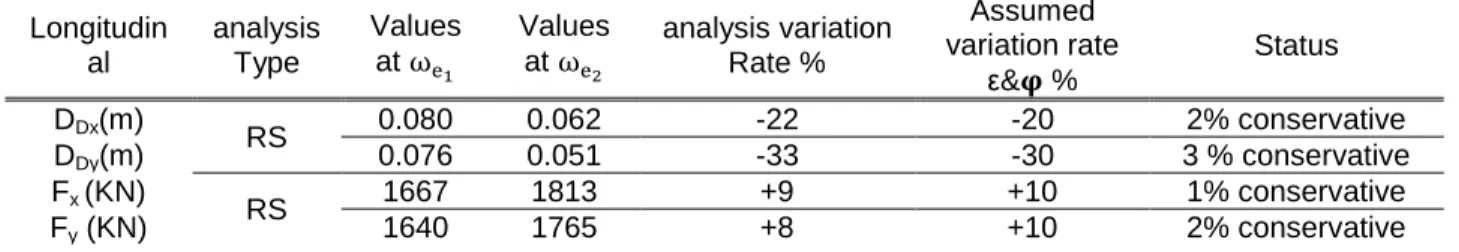
anticipated displacements and shear forces corresponding to the desired frequency for both directions. The results obtained are summarized and compared to the target displacement and force in Table 5.
Table 5 Comparing the results from analysis and simplified method in the longitudinal and transversal directions Longitudin al analysis Type Values at ωe1 Values at ωe2 analysis variation Rate % Assumed variation rate ε&𝛗 % Status DDx(m) RS 0.080 0.062 -22 -20 2% conservative DDy(m) 0.076 0.051 -33 -30 3 % conservative Fx (KN) RS 1667 1813 +9 +10 1% conservative Fy (KN) 1640 1765 +8 +10 2% conservative
These results could be taken for any other pairs of ε and 𝜑 at any damping level of the structure. The variation rates from analyses in most of the cases are in close agreement with the primarily assumed variation rates for the simplified method. Based on the results it seems reasonable to employ the method in the design of energy dissipating devices to find out the two key parameters of stiffness and damping requirements.
5. CONCLUDING REMARKS
This study proposes a simplified method for the design and retrofit of energy dissipating systems for multi-span highway bridges. Controlling the undesirable displacements in the superstructure of the isolated bridges with additional damping devices is an issue of interest for the bridge designers. Having known the needed properties, very simple and easy-to-replace dampers could be developed to account for this desired base shear and displacement variation. It is shown that by increasing stiffness and damping of these devices we could optimize the design of such dissipating segments.
Results from response spectrum analyses show the efficacy of the simplified method in estimation of new dampers for an isolated-damped bridge structure where we decide to have a desired range of base shear superstructure displacement limit.
Knowing the isolation properties and desired design or retrofit objectives the simplified method provides equations and diagrams that can anticipate the properties of the dissipating devices to comply with the design expectations. The key parameter for such a design is the damping ratio before and after the retrofit. The main outcomes of the study are:
Linear methods of analysis such as response spectrum method give close conformity with the results of the proposed method.
The proposed method provides the final damping of the structure based on its original factor. Having calculated the damping of the structure in the original status and assuming the ratio of final to original damping from the method, the target damping of the structure can be determined.
The effective stiffness of the dampers and isolators are sensitive to the disposition of the loading and its quantity which in turn changes the period of the structure. For a given isolated structure, although the isolation system remains the same all the cases considered, the effective stiffness varies because the variation of the stiffness in the dampers results in a variation in displacement and consequently variation of effective stiffness of the isolation system. This tends to increase slightly while yields in a slight augmentation in the damping of the isolation system.
6. REFERENCES
AASHTO. 2010. Guide Specifications for Seismic Isolation Design, 3rd Ed., Washington, DC.
Ashour, S. A. and Hanson, R. D., 1987. "Elastic Seismic Response of Buildings with Supplemental Damping," Report No. UMCE 87-1, University of Michigan, Ann Arbor, MI.
Chopra A. K. 2012. “Dynamics of Structures: Theory and Applications to Earthquake Engineering.” 4th Edition, Prentice Hall, Englewood Cliffs, New Jersey
Cousins, W. J., Robinson, W. H., and McVerry, G. H. 1991. “Recent developments in devices for seismic isolation.” Proc. Pacific Conference on Earthquake Engineering, Christchurch, New Zealand, pp. 221-232.
CSA-S6-06. 2006. Canadian National Highway Bridge Design Code; Canada. Eurocode 8. 2005 Design of structures for earthquake resistance -Part 2: Bridges.
Golzan, B. and Légeron F. 2010. Seismic rehabilitation of bridges with base isolation; 2nd International Structures Specialty Conference; Winnipeg, Manitoba, June 9-12
Jangid RS. and Kelly JM. 2001. “Base isolation for near-fault motions.” J. Earthquake Engineering And Structural Dynamics, 30:691-707
Kelley JM. 1999. “The Role of Damping in Seismic Isolation.” J. Earthquake Engineering and Structural Dynamics; 28:3–20.
Parducci, A. and Mezzi, M. 1991. “Seismic isolation of bridges in Italy.” Proc. Pacific Conference on Earthquake Engineering, Christchurch, New Zealand, pp. 45-56.
Priestley, M.J.N. , Seible, F., and Calvi, G.M. 1996. “Seismic design and retrofit of bridges.” John Wiley & Sons, New York, USA. P.179
Robinson, W. H. 1982. “Lead-rubber hysteretic bearings suitable for protecting structures during earthquake.” J. Earthquake Engineering and Structural Dynamics, 104, pp. 593-604.
Skinner, R. I., Beck, R. I., and Bycroft, G. N., 1975. "A Practical System for Isolating Structures from Earthquake Attack," J. Earthquake Engineering and Structural Dynamics, 13 3. pp. 297-309.
Skinner, R. I., Robinson, W. H., and McVerry, G. H. 1993. “An Introduction to Seismic Isolation.” John Wiley & Sons, New York, USA.
Thakkar, S. K. and Maheshwari R. 1995. “Study of seismic base isolation of bridge considering soil structure interaction.” Third Int. Conf. on Recent Advances in Geo-technical Earthquake Engineering and Soil Dynamics, Univ. of Missouri-Rolla, Rolla, Missouri, Vol. 1, 397-400.