HAL Id: hal-01534719
https://hal.archives-ouvertes.fr/hal-01534719
Submitted on 8 Jun 2017
HAL is a multi-disciplinary open access
archive for the deposit and dissemination of
sci-entific research documents, whether they are
pub-lished or not. The documents may come from
teaching and research institutions in France or
abroad, or from public or private research centers.
L’archive ouverte pluridisciplinaire HAL, est
destinée au dépôt et à la diffusion de documents
scientifiques de niveau recherche, publiés ou non,
émanant des établissements d’enseignement et de
recherche français ou étrangers, des laboratoires
publics ou privés.
Copyright
Extended Receive Antenna Shift Keying
Ali Mokh, Maryline Hélard, Matthieu Crussière
To cite this version:
Ali Mokh, Maryline Hélard, Matthieu Crussière. Extended Receive Antenna Shift Keying.
Interna-tional Conference on Telecommunications, May 2017, Limassol, Cyprus. �hal-01534719�
Extended Receive Antenna Shift Keying
Ali Mokh, Maryline H´elard, Matthieu Crussi`ere IETR, INSA de Rennes, France
Abstract—The new spatial modulation schemes that appeared in the early twenty-first century allow for a new exploitation of the space to an increase in the spectral efficiency of MIMO systems. These new schemes commonly referred to as spatial modulations use the index of the transmit (resp. the receive) antenna to transmit additional data. We concentrate our study on the spatial modulations at the receiver side named Receive Antenna Shift Keying (RASK) where the new or additional data is provided by the index of the antenna towards which the transmit antennas concentrate the signal energy. A classical RASK scheme with Nr receive antennas allows for the transmission of log2Nr additional bits per symbol duration. We propose a novel scheme Extended RASK where the amount of additional bits is equal to Nr. The theoretical performance of the proposed ERASK scheme is validated through simulations and compared to the performance of RASK.
Index Terms—RASK, MIMO, Spatial Modulation, Space Shift Keying, Zero Forcing
I. INTRODUCTION
Increasing the spectral efficiency, whilst minimizing energy consumption, is one of the key elements that drive research for designing future wireless communication systems. Multiple-input and multiple-output (MIMO) wireless systems have been proved to allow impressive increase in system capacity. Indeed, MIMO technology represents today one of the major step in the enhancement of many wireless communication systems [5].
Following such a trend, new space modulation (SM) schemes appeared in the early 2000s, consisting in exploiting the index of transmit or receive antennas to transmit additional information bits. In such techniques, location-dependent spa-tial information is utilized to carry additional information bits thereby boost the overall spectral efficiency. One popular SM scheme is space shift keying (SSK) [1] whose main principle is to take advantage of the various propagation characteristics associated to the different antennas of the system [2]. Given a rich scattering environment, the receiver can utilize the dis-tinct received signals from different antennas to discriminate between the transmitted information messages. This results in a simple SSK signal demodulation and then cost-effective receiver structures.
The general idea behind SM is to transmit one block of information bits in two parts by means of two complementary mapping functions. One of them consists in a classical bits to IQ-symbols mapping using a constellation diagram. The other relies on associating the remaining bits to a unique antenna index chosen from a set of transmit antennas [3]. We will further call these additional information bits ”spatial bits” to distinguish them from classical information bits carried out by IQ symbols.
In a particular SM implementation case proposed in [4] and referred to as receive antenna shift keying (RASK), the
transmitted signal carries no useful information at the level of the IQ mapping stage, but time reversal pre-coding is used to concentrate the signal energy towards a targeted antenna to transmit the spatial bits. Hence, RASK is a receive antenna SM following the antenna index mapping approach mentioned above. With RASK, a simple demodulation can be carried out based on the maximization of the real part of the received signal [4]. Since only one single antenna is targeted at a time, the spectral efficiency per channel used is however limited to log2Nr, with Nr the number of receive antennas.
A generalization of the RASK principle, further referred to as GPSM (Generalised Pre-coding aided Spatial Modulation), is proposed in [6] where the transmit antennas concentrate the signal energy towards a fixed and constant number Na > 1
of receive antennas leading to a spectral efficiency equal to blog2
Na
Nr c, where b.c indicates flooring operator.
In this paper, we propose a novel scheme referred to as Extended RASK (ERASK) to improve the spectral efficiency of spatial modulation at the receiver side by allowing a transmission towards variable number of receive antennas simultaneously. We demonstrate how ERASK provides Nr
additional spatial bits instead of log2Nr for RASK and
blog2 Na
Nr c for GPSM. We also present several detectors
that can be carried out at the receiver side as well as their expected theoretical performance. A performance comparison is then made with the classical RASK scheme on the basis of simulation results.
The rest of the paper is organized as follows. In Section II, we present the principle of the classical RASK and of the new scheme ERASK, and explain the transmission of a sequence of bits, in order to show how the spectral efficiency is increased. In Section III, the system model and the block diagram of the ERASK scheme are detailed. Thhe demodulation methods of ERASK are detailed in Section IV, with theoretical computa-tion of the Bit Error Rate. Simulacomputa-tion results are provided in Section V, and a conclusion is drawn in Section VI.
II. RASKANDERASK PRINCIPLES
In this section, we give a remainder on the RASK concept and introduce the proposed ERASK system, which can be viewed as a generalization of the RASK system.
A. Receive Antenna Shift Keying
Basically, RASK exploits the spatial modulation (SM) concept originally meant to be carried out at the transmitter side of a multiple antenna system, and applies such a concept to the receiver side through spatial focusing techniques [4]. Let Na be the number of targeted receive antennas, which
is equal to 1 for RASK, and assuming a receiver equipped with Nrreceive antennas. A RASK transmitter forms a spatial
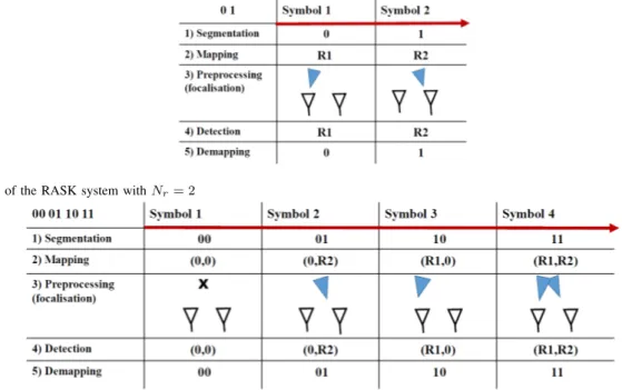
Figure 1. Example of the RASK system with Nr= 2
Figure 2. Example of the Extended-RASK system with Nr= 2
beam which changes from one RASK symbol to another so as to target one of the Nrantennas at each symbol duration Ts.
The index of the targeted antenna is therefore associated to a predefined set of information bits. In other words, RASK uses a bit-to-antenna mapping instead of a bit-to-complex-symbol mapping used in classical digital communication schemes. Consequently, the number m of bits conveyed by a RASK symbol is:
m = log2Nr (1)
Fig. 1 provides an example illustrating the transmission of a sequence of 2 bits using the RASK scheme with Nr = 2
and thus m = 1 bit per symbol. At step 1, the M-ary spatial symbols are constituted from the demultiplexing of order m of the input binary stream, with here M = 2. At step 2, the M-ary symbols are mapped into spatial symbols that determines the targeted receive antenna related to the following spatial mapping table:
• Receive antenna R1 is targeted if symbol ’0’ is sent • Receive antenna R2 is targeted if symbol ’1’ is sent.
At step 3, the transmitter performs a preprocessing so as to focus toward the targeted antenna. Then, during step 4 and 5, the receiver detects the targeted antenna among its Nr
antennas, and the estimated antenna index is converted into the bit values corresponding to a predefined spatial mapping table. Various detection algorithms, depending on the focusing scheme, can be used for the target antenna detection as detailed in [6] and reminded in Section IV.
B. Extended Receive Antenna Shift Keying
The proposed ERASK scheme is also built on the SM concept at the receiver. Unlike RASK and GPSM, where the number of targeted antennas Na is constant, for the ERASK,
Na changes each Ts with 0 Na Nr taking all possible
values, depending on the information bits, so that the number M of possible spatial symbols achieves:
M = Nr X Na=0 CNr Na = 2 Nr (2) with Ck
n the binomial coefficient giving the number of subsets
of k elements of a set of n elements. Consequently, the ERASK symbols are made of a number m of bits such that:
m = Nr. (3)
For comparative purpose according to the RASK case in Fig. 1, Fig. 2 provides an illustration of the ERASK scheme with Nr = 2. As evident from Fig. 1 concerning ERASK, steps 1
and 2 allows for forming M-ary spatial symbol with M = 4 and transmitting 2 bits during each Ts. The spatial mapping
used in this example is the following:
• no antenna is targeted (Na= 0) if symbol ’00’ is sent, • antenna R2 is targeted (Na= 1) if symbol ’01’ is sent, • antenna R1 is targeted (Na= 1) if symbol ’10’ is sent, • both antennas R1 and R2 are targeted (Na= 2) if symbol
’11’ is sent.
Hence, at step 3, the pre-processing is performed at the transmitter so as to create a beam to concentrate the transmit-ted energy towards the Na targeted antennas. At step 4, the
receiver estimates which antennas have been focused on by analyzing the amount of received energy at each antenna, and then deduces the transmitted spatial symbol. Specific detectors have thus to be designed, as proposed in the sequel.
III. SYSTEM MODEL FORERASK
In this section, we first set up the model for a communic-ation system making use of the ERASK scheme. Then, we introduce the pre-processing scheme carried out to form the spatial focusing symbols.
Figure 3. Block diagram of Extended-RASK
A. System Model
A MIMO system with Nt transmit antennas and Nr
re-ceive antennas is considered. Assuming a flat fading channel between the transmitter and the receiver, the receive signal vector can be written as
Y = H.S + N (4)
where H 2 CNr⇥Nt is the MIMO channel matrix with
elements Hj,i representing the complex channel coefficient
between the i-th transmission antenna, denoted by Ti, and
the j-th receiving antenna, denoted by Rj. Y 2 CNr⇥1 is
the vector of the received signals on all receive antennas, S 2 CNt⇥1 is the vector of the transmitted signals by all
emitting antennas, and N 2 CNr⇥1 is the vector of additive
white Gaussian noise (AWGN) samples ⌘j at the such that
⌘j ⇠ CN (0, 2n). The block diagram of the ERASK system
is depicted Fig. 3. A group of m = Nr bits is mapped to a
spatial symbolX 2 CNr⇥1 which is written as
X =hx1 x2 ... xNr
iT
where xj2 {0, A}.
The value taken by each xjentry determines the set of targeted
receive antennas such that: xj=
⇢
0, if Rj is not targeted,
A, if Rj is targeted. (5)
We can re-marque that A could also be an IQ symbol to carry additional information, but in this paper we concentrate on schemes with low complexity detection. So we only consider spatial information by assuming that A is constant.
Then, the pre-processing block transforms the vector of spatial symbolsX into a vector of transmitted signals denoted as S 2 CNt⇥1 using the pre-processing matrix W 2 CNt⇥Nr.
Consequently, the transmitted signal is written as:
S = f.W.X (6)
where f is a normalization factor used to guarantee that the average total transmit power ¯Ptis equal to A2Ts, with Tsthe
symbol duration. More precisely we have,
f =q 1 Ex{Tr(W.X.XH.WH)} =q 1 2 xTr(W.WH) (7) where Tr(.) holds for the trace of matrix and Ex stands for
the expectation over x. Since X has i.i.d. entries, the variance
2
x =Ex⇥xjx⇤j
⇤ is independent of j and comes in factor of the trace computation. Then, each entry of X is of amplitude A with a probability that can be easily verified to be of 12, leading to 2
x=A
2
2 .
B. Pre-processing Technique
The transmitter uses the pre-processing step to create a beam that will concentrate a higher amount of energy towards the targeted receive antenna than towards the other antennas. The pre-processing block requires knowledge of the channel response at the transmitter. In this paper, the Zero-Forcing (ZF) technique is employed, where the pseudo-inverse of the channel matrix is used as a pre-filter:
W = HH(H.HH) 1 (8)
This technique cancels the received energy on the non-targeted antennas. However, the required number of antennas should satisfy the constraint Nr Nt so that the matrix inversion
remains possible. It is then straightforward to obtain the expression of the receive signals:
Y =f.X + N (9)
At the level of the received antenna Rj, the received signal
then simply writes:
yj = f⇥ xj+ ⌘j. (10)
IV. ERASK RECEIVERS
To estimate the spatial symbol, the receiver should detect whether each receive antenna is targeted by the transmitter or not. This detection can be carried out with different types of re-ceiver as presented in this paper. Their respective performance and complexity are different. From Eq. (11), a given detector has to analyze the following set of signals:
8j, yj =
⇢
f⇥ A + ⌘j if Rj is targeted
⌘j otherwise (11)
Since the ZF precoding scheme is used, no interference ap-pears between receive antennas. In addition, since all targeted antenna combinations are possible with the ERASK scheme, no correlation exists between the receive antenna signals. Consequently, the demodulation process can be led through an independent and parallel signal analysis per antenna.
A. Maximum Likelihood (Real Amplitude Threshold)
Let us first derive the performance of the Maximum Like-lihood (ML) detector. The ML detector should exhaustively search among all the possible receive signatures the one that gives the closest signal to the received one. Let us denote Xk
the kth out of K = 2Nr possible transmitted signal vector
with a given combination of its entries xj(k)equal to A and
the rest being zeroed. The equation of the ML receiver can then be written as:
ˆ Xk =Arg min Xk Nr X j=1 kyj f.xj(k)k2 (12)
Owing to the parallel detection process discussed above, the ML detector can be rewritten as,
8j, xˆj=Arg min xj={A,0}ky
j f.xjk2 (13)
meaning that ˆxj is estimated separately at each antenna and
is simply obtained choosing whether A or not has been transmitted. Hence, the ML detector at each receive antenna can be carried out by means of a simple threshold detector. Suppose that the channel estimation at the transmitter for the pre-processing is perfect, the received signal at the targeted antenna will then exhibit the same phase of the emitted signal due to the phase compensation effect of the ZF precoder. Considering that the target signal xj = Ais of known phase A at the receiver, the receiver can compensate the phase of
the received signal and compare the real part obtained to a predefined amplitude threshold ⌫:
ˆ xj =
⇢
0, if <{yj⇥ e A} ⌫,
A, if <{yj⇥ e A} ⌫. (14)
where the optimal threshold is easily deduced from: ⌫ =E ⇢ <{yj0e A} + <{yj1e A} 2 = f.A 2 . (15)
with yj0 (resp. yj1) the receive signal on antenna Rj if this
antenna is not targeted (resp. targeted). Note that such a threshold can in practice be estimated during a calibration phase using dedicated pilot symbols.
Using such a threshold detector, the derivation of the theoretical Error Probability can be led as follows. First understanding that the binary error probability Pe with the
ERASK scheme is independent of the receive antenna Rj,
while reminding that the probability P(yj1)that one particular
antenna Rj is targeted is of 12, we have:
Pe=
1
2· P(yj0! yj1) + 1
2 · P(yj1! yj0). (16) Then, applying the threshold detection, we obtain:
Pe= 1
2⇥
P (⌫ <{⌘j}) + P (<{f.A + ⌘j} ⌫) (17)
Since noise samples are centered circularly Gaussian of vari-ance 2 n, we finally get Pe=P ✓ N (0, 2 n 2 ) f.A 2 ◆ =1 2 erfc ✓f.A 2 n ◆ . (18)
Such a result indicates that the system performance are driven by f which directly depends on the MIMO channel charac-teristics.
B. Power Threshold (PT)
The ML detector studied above needs the carrier synchron-ization to be led at the receiver side. Let us now consider the case of a non-coherent receiver that detects the received power at the antenna, and compares it to a pre-defined threshold. Hence, the detection process is such that:
xj =
⇢
0, if |yj|2 ⌫,
A, if |yj|2 ⌫. (19)
The optimal decision is then obtained choosing the following threshold: ⌫ =E ⇢ |yj0|2+|yj1|2 2 = (f.A)2 2 + 2 n. (20)
As in the ML detector case, the decision is made at each receive antenna in parallel, yielding:
Pe= 1 2⇥ ⇣ P(⌫ k⌘jk2) +P(kf.A + ⌘jk2 ⌫) ⌘ (21) After some mathematical manipulations detailed in the proof below, we obtain: Pe= 1 2e ⌫ 2 n +1 4 erfc ✓f.A p⌫ n ◆ erfc✓f.A +p⌫ n ◆ , (22)
which can be further simplified at low noise level as, Pe⇡ 1 4 erfc ✓f.A p⌫ n ◆ erfc ✓f.A +p⌫ n ◆ (23) As in the ML case, the performance are impacted by f.
Proof: First letting k⌘jk2 =
2 2 ⌘j0 2 where ⌘0 j 2 ⇠ X2 2
(Chi squared distribution with 2 degree of freedom), we have P(⌫ k⌘jk2) =P( 2.⌫ 2 ⌘ 0 j 2 ) = e ⌫2 (24)
On the other hand, at high signal to noise ratio (SNR), i.e. if f.A , kf.A + ⌘jk2 can be approximated by
kf.A + <{⌘j}k2, hence:
P(kf.A + ⌘jk2 ⌫) ⇡ P(kf.A + <{⌘j}k2 ⌫)
=P(|f.A + <{⌘j}| p⌫)
(25) where |f.A + <{⌘j}| = |J | follow a Folded-Normal
distribu-tion, i.e. J ⇠ N (f.A, 2/2). Then, it comes that:
P(|f.A + <{⌘j}| p⌫) =
1 2
erfc✓f.A p⌫◆ erfc✓f.A +p⌫◆ (26) which finaly leads to the result of Eq. (22). ⌅
−5 0 5 10 15 20 10−4 10−3 10−2 10−1 100 P t/σ 2 [dB] BER ERASK−ML−Nr=2, sim ERASK−ML−Nr=2 , theo ERASK−ML−Nr=4, sim ERASK−ML−Nr=4, theo ERASK−PT−Nr=2, sim ERASK−PT−Nr=2, theo ERASK−PT−Nr=4, sim ERASK−PT−Nr=4, theo
Figure 4. ERASK performance using ML and PT detectors with Nt= 8
-Theoretical and simulation comparison
V. SIMULATION RESULTS
The performance of the proposed ERASK system using both types of receivers is evaluated through the measurement of the Bit Error Rate (BER) versus the ratio between the average transmit power level and noise level, i.e. P¯t
2
n. It is assumed
that H is a MIMO flat fading channel matrix where Hj,i are
complex coefficients following i.i.d. Rayleigh distribution. The power for each sub-channel is normalized:
E⇥kHj,ik2⇤= 1
Finally, we consider that the channel response is perfectly known at the transmitter, so that perfect ZF precoding is performed. Simulations are run by implementing a sufficient number of iterations for different channel realizations, and taking the mean value of the BER for each value of P¯t
2.
Fig. 4 gives the performance of ERASK with Nr = 2 or
4 and Nt = 8using the Maximum-Likelihood (ML) and the
Power-Threshold (PT) receivers. The performance based on simulations and the analytic study are compared. As evident from the obtained curves, theoretical results perfectly match simulation results for each receiver. It is also observed that the ML receiver outperforms the PT receiver, which is easily understood since the latter detector is non-coherent and does not take advantage of the received signal phase knowledge.
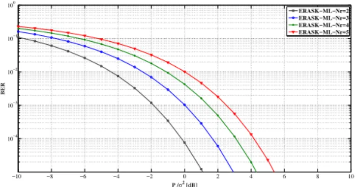
In Fig. 5, we provide the simulation results considering an ERASK system with a number Nt = 36 transmit antennas
and Nr= 2, 3, 4 or 5, leading to a spectral efficiency equal
to 2, 3, 4 and 5 respectively. The performance is evaluated using the ML coherent detection method. The results show that increasing in the order of the spatial modulation, leads to a degradation of the performance. As Nr increases, the
Zero-Forcing pre-processing technique has to deal with a higher number of antennas on which interference has to be canceled, thus degrading the power gain f of the overall system. However, it is noticed that the degradation of the performance remains reasonable between different orders of modulation. For instance, doubling the spectral efficiency from Nr= 2to Nr= 4leads to a degradation of roughly 3dB only.
For comparison purpose, the performance of the conven-tional RASK system with Nt = 36, and Nr = 4, 8, 16,
and 32 to provide the spectral efficiency of 2, 3, 4 and 5 respectively, are given in Fig. 6. Hence, the number of
−10 −8 −6 −4 −2 0 2 4 6 8 10 10−4 10−3 10−2 10−1 100 P t/σ 2 [dB] BER ERASK−ML−Nr=2 ERASK−ML−Nr=3 ERASK−ML−Nr=4 ERASK−ML−Nr=5
Figure 5. Performance of ERASK with ML receiver - Nt=36.
−10 −8 −6 −4 −2 0 2 4 6 8 10 10−4 10−3 10−2 10−1 100 Pe/σ2 [dB] BER RASK−MR−Nr=4 RASK−MR−Nr=8 RASK−MR−Nr=16 RASK−MR−Nr=32
Figure 6. Performance of conventional RASK with ML receiver - Nt=36.
receive antennas is adapted so as to reach the same orders of modulation as with ERASK. Simulations are run using a coherent detection as proposed in [4]. The obtained curves show that the RASK system outperforms the ERASK one when the order of modulation is low. However, the degradation of the performance when M is substantially raised becomes dramatic since the number of antennas at the receiver side increases exponentially. In such a situation, e.g. for Nr =
32 and Nt =36, the channel matrix becomes harder to invert,
which makes the interference cancellation on the non-targeted antennas harder to accomplish.
VI. CONCLUSION
In this paper, we proposed a very efficient way to improve the spectral efficiency related to the space dimension of spatial modulations at the receiver side. The introduced ERASK system allows for targeting any number of receive antennas simultaneously, while the classical RASK system foresees transmission towards only one receive antenna at each symbol duration. Consequently, ERASK allows the transmission of Nr
additional bits instead of log2Nr with classical RASK. We
demonstrated analytically and by simulations that the ML-based threshold receiver outperforms the maximum power-based threshold receiver at the expense of a slightly higher complexity. Moreover, for the same spectral efficiency m, the number of receive antennas needed for the novel scheme ERASK is Nr= m, which is much lower than for the RASK
scheme with which Nr = 2m. Consequently, better
which makes ERASK represent a promising technique in the perspective of increasing the capacity of SM transmissions. The ERASK scheme, can also be easily used with IQ symbols as other SM schemes as it will be taken in account in further work.
ACKNOWLEDGMENT
The authors would like to thank the SPATIAL MODULA-TION project funded by the French National Research Agency (ANR)
REFERENCES
[1] Yawgeng A Chau and Shi-Hong Yu. ‘Space modulation on wireless fading channels’. In: Vehicular Technology Conference, 2001. VTC 2001 Fall. IEEE VTS 54th. Vol. 3. IEEE. 2001, pp. 1668–1671.
[2] Jeyadeepan Jeganathan et al. ‘Space shift keying mod-ulation for MIMO channels’. In: IEEE Transactions on Wireless Communications 8.7 (2009), pp. 3692–3703. [3] Raed Y Mesleh et al. ‘Spatial modulation’. In: IEEE
Transactions on Vehicular Technology 57.4 (2008), pp. 2228–2241.
[4] Dinh-Thuy Phan-Huy and Maryline H´elard. ‘Receive antenna shift keying for time reversal wireless commu-nications’. In: 2012 IEEE International Conference on Communications (ICC). IEEE. 2012, pp. 4852–4856. [5] George Tsoulos. MIMO system technology for wireless
communications. CRC press, 2006.
[6] Rong Zhang, Lie-Liang Yang, and Lajos Hanzo. ‘Gen-eralised pre-coding aided spatial modulation’. In: IEEE Transactions on Wireless Communications 12.11 (2013), pp. 5434–5443.