UNIVERSITÉ DE MONTRÉAL
CHARGE PUMPS FOR IMPLANTABLE MICROSTIMULATORS IN LOW
AND HIGH-VOLTAGE TECHNOLOGIES
GOUTAM CHANDRA KAR
DEPARTEMENT DE GÉNIE ÉLECTRIQUE ÉCOLE POLYTECHNIQUE DE MONTRÉAL
MÉMOIRE PRÉSENTÉ EN VUE DE L’OBTENTION DU DIPLÔME DE MAÎTRISE ÈS SCIENCES APPLIQUÉES
(GÉNIE ÉLECTRIQUE) MAI 2013
UNIVERSITÉ DE MONTRÉAL
ÉCOLE POLYTECHNIQUE DE MONTRÉAL
Ce mémoire intitulé:
CHARGE PUMPS FOR IMPLANTABLE MICROSTIMULATORS IN LOW
AND HIGH-VOLTAGE TECHNOLOGIES
présenté par: KAR Goutam Chandra
en vue de l’obtention du diplôme de: Maîtrise ès sciences appliquées a été dûment accepté par le jury d’examen constitué de:
M. AUDET Yves, Ph.D., président
M. SAWAN Mohamad, Ph.D., membre et directeur de recherche M. NABKI Frédéric, Ph.D., membre
ACKNOWLEDGEMENT
First I would like to thank Almighty and M. Mohamad Sawan for giving me the opportunity, guiding me through and helping me all the way through my journey to this point in Ecole polytechnique. I would also like to thank M. Mohamad Sawan for giving me the opportunity to work on an exciting project in his team. My sincere thanks and Gratitude to M. Yves Audet and M. Frédéric Nabki for agreeing to be part of the examination board of my thesis.
Several people have been of invaluable assistance at one time or another for a long time. I think particularly of Albert, Omar, Sebastien, Hasan, and Faisal. Thank you. In addition, I thank the technicians and secretaries of the Department of Electrical Engineering for their effectiveness.
Then I thank all my friends and Polystim GR2M, especially those who have been with me through my journey in room M-5306 and M-5308 over time. I thank Amine, Arash, Sami, Ahmad, Yushan, Tariq, and others. Thank you my friends for being so kind to me.
I want to thank my family, starting with my parents, Gour and Vharti, my brother Uttam and my sister Mita for their unconditional support and encouragement. I thank my girlfriend Amrita for her unlimited patience when morale was low and it was hard to go forward.
And last but not least, I thank CMC Microsystems tools for design and manufacture of integrated circuits, as well as the Canada Research Chair in intelligent medical devices for financial support essential to this project.
RÉSUMÉ
L'objectif principal de cette thèse est de concevoir et mettre en œuvre une pompe de charge qui peut produire suffisamment de tension afin de l’implémenter à un système de prothèse visuelle, conçue par le laboratoire PolyStim neurotechnologies. Il a été constaté que l'une des parties les plus consommatrices d'énergie de l'ensemble du système de prothèse visuelle est la pompe de charge. En raison de la nature variable du tissu nerveux et de l'interface d’électrode, la tension nécessaire par stimuler le tissu nerveux est très élevé et consomme extrêmement d’énergie. En outre, afin de fournir du courant biphasique aux électrodes il faut produire des tensions positives et négatives. La génération de tension négative est très difficile, surtout dans les technologies à faible tension compte tenu des limites de la technologie. Le premier objectif du projet est de générer la haute tension nécessaire qui va consommer une faible puissance statique. La technologie de haute tension a été utilisée dans le but d’atteindre cet objectif. Le deuxième objectif est de générer la tension requise dans la technologie de basse tension et ainsi surmonter les limites de la technologie. Dans les deux cas, une attention particulière a été portée afin que personne ne latch-up apparaît pour le cycle négatif.
L'architecture de la conception proposée a été présentée dans cette thèse. La pompe de charge a été conçu et mis en oeuvre à la fois dans la technologie CMOS 0,8 μm offert par TELEDYNE DALSA et technologie 0,13 μm CMOS offert par IBM. En raison de la tension requise, 0,8 μm technologie a été utilisée pour atteindre la sortie et conçu pour minimiser la consommation de puissance statique. La même architecture a été mise en oeuvre en technologie 0,13 μm pour enquêter sur la tension de sortie obtenue avec une faible consommation électrique.
Les deux puces ont été testées en laboratoire PolyStim. Les résultats testés ont montré une variation moyenne très faible de déviation inférieure à 5% par rapport au résultat de simulation. Pour la conception en 0,8 µm, nous avons été en mesure d'obtenir plus de 25 V avec une consommation électrique très faible d’énergie statique de 3,846 mW et une charge d'entraînement maximum de 2 mA avec un maximum d'efficacité de 84,2%. Pour le même processus en 0,13 µm, les resultats ont été plus que 20V, 0,913 mW, 500 µA, et 85,2% respectivement.
ABSTRACT
The main objective of the thesis is to design and implement a charge pump that can produce enough voltage required to be implemented to the visual prosthesis system, designed by the PolyStim Neurotechnologies laboratory. It has been found that one of the most power consuming parts of the whole visual prosthesis system is the charge pump. Due to the variable nature of the nerve tissue and electrode interface, the required voltage of stimulating the nerve tissue is very high and thus extremely power consuming. Also, in order to provide biphasic current to the electrodes, there is a requirement of generating both positive and negative voltages. Generating negative voltage is very hard especially in low voltage technologies considering the technology limitations. The first objective of the project is to generate required high voltage that will consume low static power. High voltage technology has been used to achieve the goal. The second objective is to generate the required voltage in low voltage technology overcoming the technology limitations. In both cases, special care has been taken so that no latch-up occurs for the negative cycle.
Architecture of the proposed design has been presented in this thesis. The charge pump has been designed and implemented in both 0.8 µm CMOS technology offered by TELEDYNE DALSA and 0.13 µm CMOS technology offered by IBM. Because of the required voltage, 0.8 µm technology has been used to achieve the output and designed to minimize the static power consumption. The same architecture has been implemented in 0.13 µm technology to investigate the achievable output voltage with low power consumption.
Both the chips have been tested in polyStim laboratory. The tested results have shown very low variation of less than 5% average deflection from the simulation output. For the design in 0.8 µm, we have been able to get more than 25 V output with very low static power consumption of 3.846 mW and maximum drive load of 2 mA with maximum efficiency of 84.2%. For the same design in 0.13 µm, the outputs were more than 20V, 0.913 mW, 500 µA, and 85.2% respectively.
TABLE OF CONTENTS
ACKNOWLEDGEMENT --- III RÉSUMÉ --- IV ABSTRACT--- V LIST OF FIGURES --- X LIST OF TABLES --- XIV LIST OF ABBREVIATIONS AND SYMBOL --- XV
INTRODUCTION --- 1
CHAPTER 1 FUNDAMENTAL CONCEPT ON ELECTROPHYSIOLOGY --- 4
1.1 The neuron--- 4
1.1.1 The cytoplasmic membrane--- 5
1.1.2 The action potential--- 6
1.1.3 Propagation of an action potential --- 8
1.2 Visual system --- 9
1.2.1 Primary visual cortex --- 10
1.3 Stimulation electrodes --- 12
1.3.1 Reactions of the electrode-electrolyte interface --- 12
1.3.2 Interface Model --- 13
1.3.3 Types of Electrodes--- 14
1.4 Principle of electrical stimulation --- 14
1.5 Conclusion --- 17
CHAPTER 2 ADVANCED WORK IN THE FIELD--- 18
2.1 Electrical stimulation of the visual system --- 18
2.1.1 Stimulation of the retina --- 18
2.1.2 Stimulation of the optic nerve --- 19
2.1.3 Stimulation of the primary visual cortex --- 19
2.1.3.1 History --- 20
2.1.3.2 Advances in physiological level --- 20
2.1.3.3 Architecture of the visual cortex implant --- 22
2.1.3.4 Troyk’s team at the Illinois Institute of Technology --- 24
2.1.3.5 Wise’s team at the University of Michigan --- 25
2.1.3.6 Ghovanloo’s team at the Georgia Institute of Technology --- 26
2.1.3.7 Sawan’s Cortivision project of Polytechnique Montreal --- 26
2.2 Comparison of the main architectures --- 28
2.3 Architectures of charge pump --- 28
2.3.1 Chain Dickson charge pump --- 29
2.3.2 NCP-2 Architecture --- 30
2.3.3 Dynamic polarization of the substrate --- 31
2.3.4 Dual path charge pump --- 32
2.3.5 Pelliconi charge pump --- 32
2.3.6 Clock doubler charge pump --- 33
2.3.7 TPVD (Two-Phase Voltage Doubler) charge pump --- 34
2.4 Generation of negative voltage --- 34
2.5 Comparison of charge pumps --- 35
CHAPTER 3 LOW-POWER HIGH-VOLTAGE CHARGE PUMP --- 37
3.1 Introduction --- 37
3.2 Architecture of high-voltage charge pump --- 38
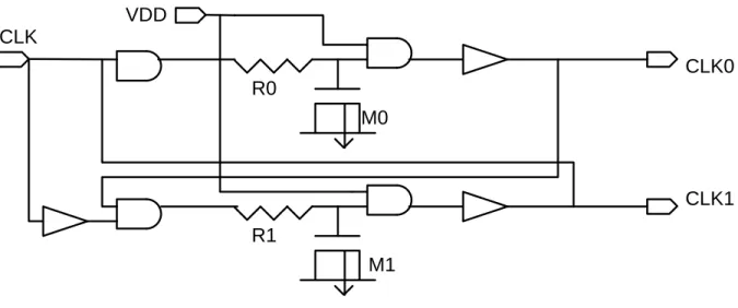
3.3 Non-overlapping clock generator --- 39
3.3.1 Selection of non-overlapping clock generators --- 40
3.3.1.1 Gate based delay cell --- 40
3.3.1.2 Current starved inverter based delay cell --- 41
3.3.1.3 RC-based delay cell --- 42
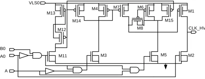
3.4 High-voltage level shifter --- 43
3.4.1 Conventional cross-coupled level-shifter --- 44
3.4.2 Bootstrapping-based level-shifter --- 45
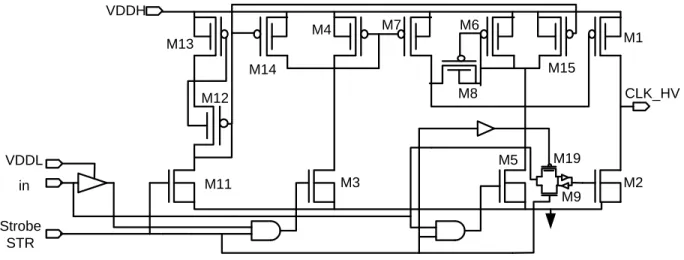
3.4.3 Dynamically controlled HV level shifters --- 47
3.4.3 Self-generating STR level-shifter --- 50
3.5 Design and Implementation of Charge Pumps --- 51
3.6 Post layout simulation --- 55
3.7 Comparison of results --- 59
3.8 Conclusion --- 61
CHAPTER 4 GENERAL DISCUSSION --- 62
4.1 Discussion on the whole system --- 62
4.2 Imperfections in chips manufactured --- 63
CHAPTER 5 CONCLUSION --- 66
5.2 Recommendation for future work --- 67
REFERENCES --- 69
APPENDIX --- 82
SCHEMATIC AND LAYOUT OF CHARGE PUMP IN 0.8 µM CMOS TECHNOLOGY (ICJPMGTM) --- 82
A-1 Top view of the chip ICJPMGTM --- 82
A-2 Design Level (ICJPMGTM) --- 83
A-2.1 High-voltage level shifter --- 83
A-2.1 Non-overlapping clock generator --- 84
A-2.1 Positive stage of the charge pump --- 86
A-2.1 Negative stage of the charge pump--- 88
A-3 Top view of the chip ICJPMGPT --- 90
A-4 Design Level (ICJPMGPT) --- 90
A-4.1 High voltage level shifter--- 90
A-4.1 Non-overlapping clock generator --- 92
A-4.1 Positive stage of the charge pump --- 94
A-4.1 Negative stage of the charge pump--- 96
LIST OF FIGURES
Figure 1.1: Physiology of the neuron. Modified from (StateMaster, 2009). ... 4 Figure 1.2:Trigger mechanism of an action potential. (a) Temporal variation of the membrane
potential. (b) Illustrates the mechanism of ion channels in the membrane. ... 7 Figure 1.3: Propagation of an action potential along an axon militated neuron. ... 8 Figure 1.4: Anatomy of the human visual system. Modified from (Coulombe, 2007). ... 9 Figure 1.5: Organization of the primary visual cortex (Cortical module) (McGill University,
2009). ... 11 Figure 1.6: Electrode-tissue interface model ((Laaziri, 2005) ... 13 Figure 1.7: Different examples of implantable electrodes. (a) Electrode sheath. From (Cramp,
1999). (b) Surface electrodes. From (Rodger et al., 2006). (c) Matrix microelectrodes. From (Ayoub, 2007). ... 15 Figure 1.8: Intensity-duration curve defining the excitation threshold of the neuron (Merrill et al., 2005)……….……… 16 Figure 1.9: Biphasic pulse train of current with the set of parameters of stimulation (Merrill et
al.,2005)……… 16 Figure 2.1: (a) Matrix microelectrodes Utah. From (House et al., 2006), with the authorization of
JNS (b) Photograph of the surface of the visual cortex after six months of implantation. Spots are visible at the site of implantation. From (Normann et al., 1999) ... 21 Figure 2.2: Correspondence visio-optic of V1 cortex (red), V2 (blue) and V3 (green). (a)
Phosphenes in the visual field according to (b) stimulation sites in the occipital cortex. Modified from (Srivastava et al., 2007). ... 22 Figure 2.3: Typical architecture of a cortical visual prosthesis (Coulombe et al, 2007). ... 23 Figure 2.4: Implant of the Illinois Institute of Technology: (a) The implant modules 64 channels
in its encapsulation, (b) Intracortical electrodes used in vivo tests. (Troyk, 2009). ... 24 Figure 2.5: Implant of the University of Michigan. (a) Probe to eight channels. (b) Microsystem
Figure 2.6: Interestim implant-2B 32 channels from North Carolina State University. (a) Top view showing the implant secured with epoxy. (b) Bottom view showing the inductance
of the telemetry system. From (Ghovanloo & Najafi, 2007) ... 26
Figure 2.7: Cortivision intracortical visual implant. (a) Illustration of the complete implant. (b) Photomicrograph of stimulation module. From (Coulombe, 2007). ... 27
Figure 2.8: Dickson charge pump of four stages (Pylarinos, 2008). ... 29
Figure 2.9: NCP-2 charge pump of four stages. From (Wu & Chang, 1998) ... 31
Figure 2.10: Charge pump with dynamic biasing of the substrate. From (Shin et al., 2000) ... 32
Figure 2.11: One stage of the Pelliconi charge pump. From (Pelliconi et al., 2001) ... 33
Figure 2.12: Clock doubling circuit. From (Huang et al., 2008) ... 33
Figure 2.13: TPVD charge pump with one stage (Saiz et al, 2011) ... 34
Figure 3.1: Proposed high-voltage charge pump architecture. ... 39
Figure 3.2: Non-overlapping clock generator circuits based on gate delay cells. ... 40
Figure 3.3: Non-overlapping clock generator circuits based on current-starved inverter delay cells. ... 41
Figure 3.4: Non-overlapping clock generator circuit based on RC-based delay cells ... 43
Figure 3.5: Schematic of conventional cross-coupled level shifter circuit ... 45
Figure 3.6: Schematic of bootstrapping-based level shifter circuit ... 46
Figure 3.7: Schematic of the dynamically controlled high-voltage level-shifter schematic (Doutreloigne et al.) ... 49
Figure 3.8: Schematic of the modified dynamically controlled high-voltage level-shifter. ... 50
Figure 3.9: Experimental result of the modified dynamically controlled high-voltage level-shifter ... 51
Figure 3.10: (a) Positive Charge Pump Block. (b) Negative Charge Pump Block. ... 51
Figure 3.11: Stages for positive (a) and negative (b) charge pump ... 52
Figure 3.12: Side view of the wafer showing the well connections of the negative charge pump. (a) Deep N-wells tied to the source of the PMOS devices with the possible forward-biased PN junctions shown, (b) Deep N-wells tied to the ground (Ethier et all, 2009) .... 53
Figure 3.14: Side view of the wafer showing the well connections of the negative charge pump
for 0.13µm CMOS technology. ... 54
Figure 3.15: Layouts of the proposed charge pumps. ICJPMGTM (design in 0.8µm CMOS technology, A= Non-overlapping clock generator, B=High voltage level shifter, C=Positive charge pump, D=Negative Charge pump) and ICGPMGPT (design in 0.13µm CMOS technology, A=Non-overlapping clock generator, B=High voltage level shifter, C=Positive charge pump, D=Negative charge pump and Comparator, E=Load Capacitors for positive and negative charge pumps) ... 56
Figure 3.16: Simulation result of the output voltage with no load and 1 mA load. ... 57
Figure 3.17: Experimental result of the output voltage with no load. ... 57
Figure 3.18: Output voltage drop with the increase of load current ... 58
Figure 3.19: Efficiency of the charge pump with respect to load current increase. ... 58
Figure A.1: Top view layout design of charge pump in 0.8 µm CMOS technology (ICJPMGTM) ... 82
Figure A.2: Schematic of the high-voltage level shifter ... 83
Figure A.3: Layout of the high-voltage level shifter ... 83
Figure A.4: Schematic of the non-overlapping clock generator ... 84
Figure A.5: Layout of the non-overlapping clock generator ... 85
Figure A.6: Schematic of the positive stage of the charge pump ... 86
Figure A.7: Layout of the positive stage of the charge pump ... 87
Figure A.8: Schematic of the negative stage of the charge pump ... 88
Figure A.9: Layout of the negative stage of the charge pump. ... 89
Figure A.10: Top view of the chip ICJPMGPT ... 90
Figure A.11: Schematic of the high voltage level shifter ... 91
Figure A.12: Layout of the high voltage level shifter ... 91
Figure A.13: Schematic of the non-overlapping clock generator ... 92
Figure A.14: Layout of the non-overlapping clock generator ... 93
Figure A.15: Schematic of the positive stage of the charge pump ... 94
Figure A.16: Layout of the positive stage of the charge pump ... 95
Figure A.18: Layout of the negative stage of the charge pump ... 97
Figure A.19: Schematic of the comparator ... 98
Figure A.20: Layout of the comparator ... 99
Figure A.62: Output of high voltage level shifter (experimental result) ... 100
LIST OF TABLES
Table 2.1: Comparison summary of the main visual intracortical implants. ... 28 Table 3.1: Simulated features for both charge pump designs ... 59 Table 3.2: Parameters and result comparison. ... 60
LIST OF ABBREVIATIONS AND SYMBOL
ATP Adenosine Triphosphate BJT Bipolar Junction Transistor LGN Lateral geniculate nucleus
CMOS Complementary Metal Oxyde Semiconductor RCP Reduced concentration of Products
DC Direct Current
FPGA Field-Programmable Gate Array IC Integrated Circuit
MOSFET Metal Oxyde Semiconductor Field Effect Transistor OMS Organisation Mondiale de la Santé
n Slope factor Vt Thermal voltage
VA Early voltage
INTRODUCTION
Biomedical engineering has shown a great prospect in recent past to restore physiological functions. Research in the field of biomedical engineering has experienced remarkable growth in recent decades. This excitement is particularly noticeable in the case of implantable medical devices. Following the technical and commercial success of the pacemaker and the cochlear implant, the pacemakers become commonly considered an avenue to restore physiological functions lost. This trend is supported by the miniaturization of microelectronics circuits to integrate to systems of increasing complexity surfaces on the order of mm2.
Blindness is a typical example of a physiological disorder that much interest in the scientific community for a long time. In April 2010, approximately 39 million blind people worldwide have been identified (World Health Organization [WHO], 2010). According to the organization, 25% of this blindness cannot be prevented or treated in normal way. To be able to handle other cases considered irreversible, many researchers are studying the development of electronic prostheses enable patients to regain functional vision. It is in this context, the PolyStim neurotechnology laboratory at the École Polytechnique Montreal has initiated the project Cortivision, a visual implant directly stimulating the visual cortex. The latest advances in this project show a working prototype successfully used in experiments in vivo in rats (Coulombe, 2007).
An important constraint for any implantable device is power consumption. In the case of Cortivision, the implant is powered by an external battery whose power is transmitted by a wireless inductive link. The system being used on a daily basis due to several hours per day, it is crucial to limit power consumption to extend battery energy of the implant. A second design constraint of the intracortical microstimulator is the high impedance of the interface between the electrode and the biological tissue. This requires the use of high voltages often incompatible with processes low voltage.
The main objective of this research project is the realization of a intracortical microstimulator with reduced power consumption compared to the previous prototype (Coulombe, 2007, S. Ethier, 2011). To achieve this, new forms of potentially more effective stimuli are generated and can be compared to the basic design. The idea is to generate a charge pump which can produce enough voltage to provide the required supply. Because producing high voltage supply results in consuming very high power, considerable reduction of the power consumption is required by the circuitry as a total of more than 1000 channels is considered. The resulting prototype will experimentally validate the results obtained using the model developed by cortical Polystim (Robillard, 2008). Another objective of this work is to reproduce the whole design in low voltage technology to produce the highest amount of output voltage. The limitations of low voltage technology make it more difficult to produce enough supply voltage but it is necessary to integrate the whole system in a single chip also to reduce power consumption. This circuit is essential for the prototyping of a fully implantable system including no discrete component.
This master thesis consists of five chapters. The first chapter summarizes the basic concepts of physiology that are necessary for the identification of system specifications. It is about the first neuron, the basic unit of the nervous system and its excitation process. Second, the human visual system is briefly described with an emphasis on the visual cortex. Thirdly, it is a question of the interface formed between the electrodes and tissues, as well as its model. Finally, the basic principles of functional electrical stimulation are described.
The second chapter is devoted to a review of the literature. First, an overview presenting the various existing visual implants and their characteristics is performed. Subsequently, a review of various circuits useful for this project is presented. These circuits involve the generation of various forms of pulses used for stimulation and the generation of high voltages.
As of third chapter, the full design and description of the low-power high voltage charge pump has been described. Both simulation and experimental results have been discussed. Then a comparison of different work has been presented.
A general discussion by linking different parts of the memory is performed in the fourth chapter. Further discussions with defective circuits manufactured and not present in the article are also found.
Finally, the conclusion summarizes all the work done in this thesis and recalls the important results. Recommendations based on results which relate to the project's next steps Cortivision are also mentioned.
CHAPTER 1
FUNDAMENTAL CONCEPT ON ELECTROPHYSIOLOGY
First, it is important to recall some concepts of neuron physiology and bioelectricity necessary for understanding the phenomena and systems forming the heart of this thesis. This first chapter includes these key concepts by starting with the neuron and its principle of excitement. Subsequently, the entire visual system is described, particularly the primary visual cortex. Then, types of stimulation electrodes and how they form interface with living tissue are described. Finally, there is the question of functional electrical stimulation, its parameters, as well as notions of security.
1.1 The neuron
The neuron is the basic element of the nervous system. This cell allows the generation and propagation of nerve spikes in the body. Figure 1.1 illustrates the anatomy of a typical neuron.
Figure 1.1: Physiology of the neuron. Modified from (StateMaster, 2009).
The dendrites are considered as inputs of the neuron. These capture the stimuli from cells cyclic up. At the other end, the terminal buds are outputs to transmit nerve spikes to other neurons. The connection between two neurons, called the synapse is not direct. It is rather a narrow space in
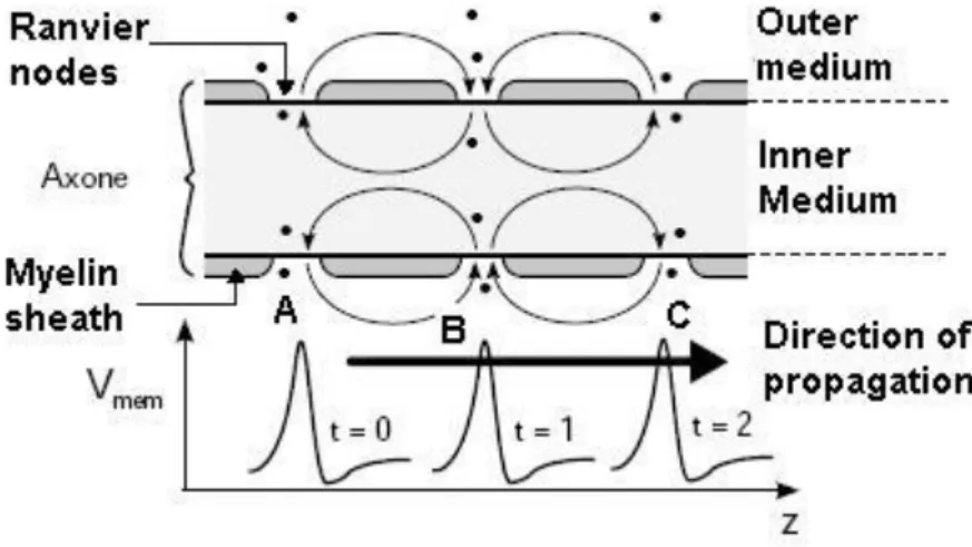
which biochemical travel are called neurotransmitters. These are released by the terminal buttons of a neuron transmitter to the arrival of nerve spikes and are picked up by the dendrites of the receiving neuron. The uptake of neurotransmitters regenerates nerve spikes that converge towards the center of the receptor neuron, that is to say the soma. Treatment of all signals received by the dendrites is then carried out according to the type of neuron. The response of the soma is then propagated along the axon. Myelin sheath, consisting of Schwann cells wrapped, wraps the axon of a neuron. Some sections of the axon are not covered; they are called nodes of Ranvier. This structure aims to accelerate the propagation of spikes along the axon can be over a meter long, depending on the type of neuron.
1.1.1 The cytoplasmic membrane
The cell membrane of the neuron plays a fundamental role in the generation and propagation of nerve spikes. As for all cells in the body, it is composed of a double layer of phospholipids, low permeability layer molecules and ions. However, it is traversed by proteins that act as channels and as ion pumps. These proteins facilitate the dissemination and allow the selective transport of ions between the intracellular and extracellular environments, ensuring self-regulation of the cell. Major ions involved in bioelectric phenomena are Na+, Cl-, K+ and Ca2+. At equilibrium, the extracellular medium typically has a higher concentration of sodium ions and chlorine, while the intracellular medium has a higher concentration of potassium ions.
The concentrations of various ions in the intracellular and extracellular environments are such that there is a difference in electric potential between sides of the cytoplasmic membrane. This transmembrane potential is conventionally defined as the neuron potential, normally is about -70 mV. It is the resting potential, also known as the equilibrium potential or rest of the cell. Membrane voltage is at the heart of bioelectric phenomena of the cell. For example, ion channels have a number of gates of that state, that is to say, open or closed, depending on what the potential is.
This allows them to distribute the ions through the membrane or block. These are the mechanisms for opening and closing different gates that allow the generation of action potentials.
1.1.2 The action potential
Several phenomena can disrupt the electrical balance of the neuron. In the case of sensory neurons, the physical changes of the environment, such as temperature, pressure or light, have a direct effect on the internal potential. Another possible disruption is receiving a nerve impulse from a neighboring neuron. The last case is a local variation of extracellular potential generated by an external electrical stimulation, for example.
These disturbances of balance electrochemical cell change its transmembrane voltage. If this is kept under the excitation threshold of the neuron (about -55 mV), the mechanisms of diffusion and ion transport restore balance and no excitation is generated. On the other hand, when the membrane potential exceeds this threshold, spike is triggered. This is the action potential. The latter is generated by a mechanism of the type "all or nothing", that is to say that the amplitude and duration of the action potential are independent of the intensity of the stimulus to its origin.
The phenomenon is illustrated briefly in Figure 1.2. First, in step 1, the neuron is in balance and membrane potential of -70 mV. A stimulus is thereafter increased to the threshold potential internal excitation of the cell. From that moment there is local depolarization of the membrane of the neuron, which corresponds to step 2 in Figure 1.2. This is a sharp increase in the transmembrane voltage caused by the massive influx of Na+ ions inside the cell as a result of the opening of the gates of sodium channels. When the action potential reaches its maximum value of about 35 mV, repolarization phenomenon is switched on. So one of the gates of the sodium channels closes, and the door opens potassium channels, allowing a major outflow of K+ ions to the extracellular medium. The result is a decrease in membrane potential, as is shown in step 3, resulting in hyperpolarization of the cell membrane. This means that the membrane potential falls below its equilibrium value. At this time, or in step 4, it pumps Na+ - K+ exchange of Na+ (outward) and K+ (inward) to rebalance the internal potential of the neuron. These transfers occurring ions against the electrochemical gradient diffusion pumps, expend energy provided by adenosine triphosphate (ATP) to achieve them.
Figure 1.2: Trigger mechanism of an action potential. (a) Temporal variation of the membrane potential. (b) Illustrates the mechanism of ion channels in the membrane (StateMaster, 2009).
The action potential amplitude with fixed stimulus intensity to its origin is rather modulated by the firing frequency of action potentials of the neuron. This frequency, known as firing frequency, has a limit. Immediately after the onset of an action potential, there is a period during which the membrane is insensitive to extracellular potential, thus preventing the generation of a second action potential. This period, due to the hyperpolarization of the membrane, is called refractory period.
1.1.3 Propagation of an action potential
Once triggered, the spike must be transmitted through the nervous system to be interpreted. The propagation of the action potential along the axon is explained by the theory of the cable (Gulrajani,1998), the phenomenon is shown schematically in Figure 1.3. Briefly, the intracellular and extracellular environments are considered drivers of ionic current. When action potential is triggered at a point A of the membrane, the membrane potential is changed here. The potential difference between point A and point B then generate intracellular and extracellular ionic currents from A to B during depolarization. These currents depolarize the membrane B, and if they reach the threshold of excitability, trigger another action potential at this point. This phenomenon is repeated from B to C and so on throughout the axon, it is a chain reaction conservative.
Figure 1.3: Propagation of an action potential along an axon militated neuron(StateMaster, 2009).
When the axon is militated, the myelin sheaths prevent any passage of ions through certain sections of the cell membrane. Regions of the membrane where action potentials can be generated are then discretized by nodes of Ranvier as shown in Figure 1.3. The distance between nodes causes the triggering of an action potential at a point allows the direct excitation of the next node without being slowed down by its own refractory period. This type of propagation, called salutatory conduction, then takes place more rapidly in the absence of myelin.
Notions concerning the action potential are introduced; the next section deals with the human visual system, especially the primary visual cortex, which represents an area of interest in this work.
1.2 Visual system
The visual system in humans is critical and complex. It mainly extends in the retina to the visual cortex located in the back of the brain. Several other cortical areas are solicited for more cognitive processing, but they will not be considered here. Figure 1.4 shows the anatomy of this system and the path that the information captured by the eye.
The light is first converted into nerve spikes by the retina at the back of each eye. They are composed of three layers of neurons with specific functions, are the photoreceptors, bipolar neurons and ganglion cells. Already at the retina, the visual information processing is performed. The axons of the ganglion cells meet at a point on the retina, called optical disc to form the optic nerve. It enters the skull and travels the optic chiasm, where there is partial crossing of axons and the optic tract. Each of these points has a role in the treatment of nerve spikes. Axons then reach the lateral geniculate nucleus (LGN), one relay before the primary visual cortex. The LGN is composed of six distinct layers of cells, each receiving a particular projection from the retina. Up to this point, the propagation and processing of signals generated by the retina are performed in parallel. In addition, it should be noted that about 80% of excitatory connections, from the LGN to the primary visual cortex, it performs so important feedback on the treatment at the LGN. Finally, the information is transmitted to the primary visual cortex through projections called optical radiation.
1.2.1 Primary visual cortex
The visual cortex consists of several dozen areas performing simple treatments, such as the analysis of orientation and color, or treatments such as cognitive and associative recognition of objects or spatial positioning. Only the primary visual cortex, also known as striate cortex or V1, is considered in this work since it is the entry point for more complex processing of visual information.
From a total thickness of 2 mm, the primary visual cortex is located in the posterior occipital lobe. It contains many types of neurons, mainly pyramidal cells and stellate. This area of the cortex is divided into six distinct layers, each having a composition and functions. By studying the neuronal connections between these layers and between different areas, it has been shown that the signals come from the LGN in the visual cortex by layer 4 of area V1. This layer, especially the sub-layer 4C, plays a role in the progression and treatment of information in vision. Subsequently, the information is projected to layers 2, 3 and 5, in addition to feedback to
the LGN. These layers retransmit the signals received from the layer 4 surrounding areas for more advanced treatment.
In this arrangement adds layers of primary visual cortex organization in columns, as shown in Figure 1.5. Initially, the layer 4C is divided evenly in the ocular dominance columns by alternating bands of about 0.5 mm wide. In a second step, the columns are spread orientation in the direction orthogonal to that of the dominant eye. For each of these columns in the cortex, electrical activity is dependent on a fixed orientation of the light stimulation. It has been shown experimentally that 180o are covered by 1 mm on average. Finally, the last column elements are stains. These cylindrical pillars collect and process information about color. In Figure 1.5a, is schematized cortical module, that is to say, a block of 2 mm × 2 mm with two complete groups of ocular dominance twice orientation of 180o and 16 spots. As a summary, Figure 1.5b represents a column detailed V1 cortex on which the various layers and the signal inputs are identified. Inputs from magnocellular and parvocellular layers respectively are 1 and 2, and 3 to 6 of LGN. They are different type of retinal ganglion cells which are projected.
Figure 1.5: Organization of the primary visual cortex (Cortical module) (McGill University, 2009).
1.3 Stimulation electrodes
In the biomedical field, the electrodes are essential for both signal acquisition and biological tissue stimulation. They have a function of transducer for converting the electrical current in the ion current, and vice versa. This conversion is done using the complex electrochemical reactions occurring at the electrode-tissue interface. The impedance of this interface is non-linear and depends on several factors such as stimulus measure/inject (intensity, frequency), the electrode (material, geometry, surface) and the environment (temperature, ion concentrations).
1.3.1 Reactions of the electrode-electrolyte interface
Contact between an electrode and biological tissue is summarized by an electrochemical phenomenon between a metal and an electrolyte (Merrill et al., 2005). The cell medium is considered electrolyte containing ions Na+, Cl- and K-. Once the electrode is working, an interface consisting of a double layer of charge is formed at its surface. This is the result of redistribution of loads in both environments, the adsorption of some anions and attraction of polarized molecules such as water molecules. The equilibrium is reached.
When a current is injected from the electrode, as in the case of stimulation, the amount of charge at the interface is changed and the balance is disturbed. Two types of charge transfer between the metal and the electrolyte can then occur depending on the number of injected charges. When this amount is low, the charge transfer is said capacitive or non-faradaic that is to say that no electron passes through the interface. The result is a redistribution of charges in the electrolyte. This phenomenon is reversible by removing the same amount of charge of the electrode. When the disturbance of the balance is too high, a second type of charge transfer occurs or injection faradic charges. In this case, electrons are injected into the electrolyte causing oxidation-reduction reactions at the interface whose general form is given by equation (1.1)
Where O is oxidized species, the reduced species R and n are the number of electrons transferred. Depending on various factors such as the material and the electrode surface, and the intensity and duration of stimulation, ions toxic to tissues can be produced and released into the cell medium. These reactions are all reversible. According to their speed of reaction, it is possible that harmful products are distributed far from the electrode to a reverse flow of charges can be recovered.
1.3.2 Interface Model
A model of the electrode-tissue interface considering the different charge transfer is an essential tool for the design of a pacemaker. Indeed, an electrical point of view, it is crucial to have a good knowledge of the output load circuit, that is to say, the impedance of the contact. Many researchers have focused on the modeling of the interface giving rise to models more refined (Laaziri, 2005). Recently, Laaziri proposed a more realistic model as shown in Figure 1.6.
Figure 1.6: Electrode-tissue interface model ((Laaziri, 2005)
Here is a brief description of the component. First, ZCPA is the impedance of the capacity
corresponding to the Cdl ionic double layer formed at the surface of the electrode. This capability
models the charge transfer non-faradaic. The amplitude of the impedance depends on the stimulus and the material of the electrode. Then RCT represents the resistance of faradaic charge
transfer between the electrode and the tissue of the stimulation current. The impedance ZW,
called the Warburg impedance, modeled the effect of ion diffusion around the electrode. This impedance is dependent on the stimulus highly complex, and the surface of the electrode and ion
concentration of the cell medium. Finally, resistance Rel and the voltage source Eel correspond to
the resistance of the extracellular medium and the equilibrium potential of the interface between the electrode and tissue.
1.3.3 Types of Electrodes
Depending on the application and the location of the body where they are used, the electrodes can take different forms. Figure 1.7 shows some examples of implantable electrodes. Insulated electrodes, or electrodes cuff, are useful for the stimulation of the peripheral nerves since they allow direct contact with them. For the acquisition of signals or tissue stimulation, surface electrodes are commonly used. Finally, with its pointed, the microelectrode penetrates tissue with stimulation directly to a given depth. Grouped into matrices, the microelectrodes can provide a high density, which is desirable for intracortical stimulation.
For its part, the implant project of Cortivision has been done using microelectrode array. Only the tips are exposed to about 100 microns, the surface of contact with the cortical tissue is reduced. Therefore, the impedance of the electrode-tissue interface is high. According to measurements made by Pigeon, it can reach approximately 100 kΩ for low-frequency stimulation (Pigeon, 2004).
1.4 Principle of electrical stimulation
As mentioned above, action potentials can be triggered in excitable tissues, such as the cortex, artificially with electrical stimulation through an electrode. To be effective, the stimulus must succeed in raising the transmembrane voltage above the threshold for triggering an action potential.
Figure 1.7: Different examples of implantable electrodes. (a) Electrode sheath. From (Cramp, 1999). (b) Surface electrodes. From (Rodger et al., 2006). (c) Matrix microelectrodes. From (Ayoub, 2007).
1.4.1 Parameters
In general, the stimuli used are rectangular biphasic pulses of current. Tissue response to these stimuli has been characterized and is shown in Figure 1.9. This is the time-intensity curve showing the threshold current density and duration of a pulse which triggers action potentials in tissue. This threshold Ith follows the following equation:
(1.2) Where ∆T is the pulse duration, current I0 is the base current or the current absolute minimum
needed to excite neurons, and τ is the minimum time to allow current to reach 2I0 which is the
Figure 1.8: Intensity-duration curve defining the excitation threshold of the neuron (Merrill et al., 2005).
To ensure the effectiveness of the stimulation, it is generally composed of several biphasic pulses repeated at a given frequency, as shown in Figure 1.10. These pulses are also grouped into trains, repeated themselves at a given rate. To maximize the effectiveness of the stimulator, it is advantageous for all stimulation parameters of Figure 1.10 to be variable. Indeed, the effect of each of these parameters is not fully known and may vary from one person to another, it is essential that the microstimulator be as flexible as possible.
Figure 1.9: Biphasic pulse train of current with the set of parameters of stimulation (Merrill et al., 2005).
Different modes of stimulation are also possible. Indeed, biphasic pulses may be injected through a single electrode. The return current is then recovered by a reference electrode. It must have a very large contact surface to reduce its impedance and maintain approximately constant potential during stimulation. In this case, the faradaic charge transfer is limited (Merrill et al., 2005). This mode is called monopolar stimulation. Stimulation can also be between two active electrodes. First electrode stimulation current injected while the second completes the circuit by connecting to one of the supply voltages according to the polarity of the pulse. This is called bipolar stimulation.
1.5 Conclusion
Physiological concepts necessary for understanding the main topic of this master thesis were briefly summarized in this first chapter. The initiation and propagation of action potentials and detailed description of the neuron and the cell membrane has been given. Subsequently, the entire visual system was flown with a particular emphasis on the primary visual cortex. Then, as discussed, stimulation through electrodes, the electrochemical reactions at the interface with the tissues of the model and power consumption have been described. Finally, based on these concepts, certain fundamental principles of stimulation were set to ensure patient safety while promoting effectively.
CHAPTER 2
ADVANCED WORK IN THE FIELD
This second chapter aims to present the state of the art in stimulation of the visual system through a review of relevant work leading to this thesis. Electrical stimulation of the visual system is discussed according to the different possible strategies. The emphasis is on intracortical stimulation with a brief history of basic and advanced existing systems, including the implant team of Polystim. We then question the effectiveness of stimulation, as well as some other areas to improve. Then, various implementations of these circuits generating high voltage are inventoried. Finally, the last section discusses the selection of high-voltage circuits designed to be effective for biphasic current pulse generation at the electrodes and various architectures to produce such high-voltage levels.
2.1 Electrical stimulation of the visual system
The various methods of restoring functional vision depend on the site of stimulation in the visual system, which are the retina, the optic nerve and the visual cortex. In all these cases, it is possible to perceive a sensation points light called phosphenes in the visual field of the user. The idea behind any visual prosthesis is to recreate images understandable for the blind from several of these phosphenes.
2.1.1 Stimulation of the retina
A first approach is the visual prosthesis stimulation of the retina. Two types of retinal stimulator are under development: the sub-retinal implant (Shire et al., 2009) and epi-retinal implant (Weiland et al., 2008). First, the sub-retinal prosthesis is implanted under the retina and replaces the deficient photoreceptors by directly stimulating the healthy ganglion cells. It has the
advantage of being held in place by the retina. In the case of epi-retinal implant, the pacemaker is fixed on the surface of the retina and stimulates using surface electrodes.
The main advantage of stimulating the retina is the natural treatment of visual information downstream is involved. Good resolution and image quality can be hoped for. This technique is less invasive than other types of visual prostheses (Normann et al., 1999). However, the blindness of the major diseases of the retina and optic nerve cannot be treated by this method. In addition, in the case of epi-retinal implant, the prosthesis must be firmly established in the retina, which has about 500 microns thick, not to win with saccades of the eye. Finally, the ganglion cells have several roles in the encoding of visual information; it is not clear what is their response was to electrical stimulation (Normann et al., 1999).
2.1.2 Stimulation of the optic nerve
Electrical stimulation of the optic nerve using electrode cuffs provides visual perceptions (Veraart et al., 1998). This avenue is taken to achieve a visual prosthesis for the user to recognize patterns given (Veraart et al., 2003).
This approach is a better way of stimulation of the retina. In addition, compared to other techniques, the number of electrodes required to generate a given number of phosphenes is much lower. However, the control over them is much more complex. The surgery required for implantation is major and invasive. These drawbacks mean that this type of implant is uncommon and has not been successful so far.
2.1.3 Stimulation of the primary visual cortex
A final possible strategy to restore functional vision is the stimulation of the visual cortex. Having its entry point much further downstream in the flow of visual information, this method has the advantage of covering the widest variety of causes of blindness. It is possible to stimulate the surface of the cortex (cortical stimulation) or at a given depth with penetrating electrode (intracortical stimulation). Being attached to the surface of the brain, such an implant is to be
protected by the skull, but it faces from mechanical stresses among others cortex itself. (Normann et al., 1999).
2.1.3.1 History
Since the 1960s, it is known that the local electrical stimulation of the visual cortex gives rise to phosphenes. Based on this, the idea of a visual prosthesis for reading and facilitating travel for the Blind has fascinated many research teams, including Brindley and Dobelle (Brindley & Lewin, 1968; Mladejovsky & Dobelle, 1974). Their groundbreaking work, considered the genesis of this research, as a first characterization of the appearance of phosphenes by the stimulation parameters and the location of the electrodes on the occipital lobe. They also raised awareness of the major limitations of this approach, as the threshold current required for the generation of phosphenes (of the order of mA) and look diffuse and difficult to control.
More than two decades later, other experiments on sighted subjects (Bak et al., 1990) and a blind about 22 years (Schmidt et al., 1996) took place with penetrating microelectrodes. It has been shown that the threshold current for the onset of phosphenes are then 10 to 100 times lower than with surface electrodes, a few tens of micro amps. In addition, the phosphenes are more stable and better defined.
In addition to qualitatively quantify the effect of stimulation parameters, Schmidt noted that the use of pulse trains allows for continuous phosphenes. He also established a spacing of 500 nm between two electrodes is sufficient to display two distinct phosphenes. The results presented by Schmidt (Schmidt et al., 1996) are still today a reference on the effects of stimulation parameters on perceived phosphenes in a blind human subject. They have caused a renewed interest for unprecedented visual prostheses.
2.1.3.2 Advances in physiological level
Consideration overlooked by previous work is the long-term effect of the introduction of a large amount of microelectrodes in the striate cortex. Dr. Normann's team at the University of Utah
conducted a series of experiments on cats with a matrix of 10 × 10 microelectrodes separated by a distance of 400 microns (Normann et al., 1999 , Rousche & Normann, 1999). This matrix, shown in Figure 2.1a is biocompatible since it is made of silicon and its ends are covered with platinum. After six months of implementation, analysis of the cortex of subjects showed gliosis and accumulation of fibrous tissue at all implantation sites as shown in Figure 2.1b. Tissues react to the presence of the electrodes, thus increasing the electrical impedance and generating stresses. However, the majority of electrodes of the prosthesis were still functional acquisition and stimulation after a period as long as three years (Normann et al., 1999).
Figure 2.1: (a) Matrix microelectrodes Utah. From (House et al., 2006), with the authorization of JNS (b) Photograph of the surface of the visual cortex after six months of implantation. Spots are visible at the site of implantation. From (Normann et al., 1999)
For his part, Dr. Troyk of the Illinois Institute of Technology and his team focused their research to the location of phosphenes with in vivo tests on monkeys (Troyk et al., 2002; Srivastava et al. 2007). Their goal is to better understand and define the correspondence visuotopic, that is to say the relationship between stimulation sites on the primary visual cortex and the position of occurrence of phosphenes in the visual field. They were able to arrive at qualitative conclusions encouraging, but much remains to be done in this area.
Figure 2.2: Correspondence visio-optic of V1 cortex (red), V2 (blue) and V3 (green). (a)
Phosphenes in the visual field according to (b) stimulation sites in the occipital cortex. Modified from (Srivastava et al., 2007).
Despite these advances, there are significant drawbacks to the cortical visual prosthesis. Initially, a portion of the natural processing of the influx is bypassed, limiting the quality of the perceived image. In a second step, the implementation of this type of device is invasive and serious complications can occur. In a third step, a correspondence visuotopic one must first be established for each user. Finally, some studies suggest that, due to the plasticity of the brain, some areas of the occipital cortex tend to be retrieved by other senses, such as hearing, among blind people. It would be reasonable to believe that the correspondence visuotopic can be changed over time. However, this brain plasticity could be beneficial, as is the case for the cochlear implant (Fernandez et al., 2005), since some adaptation consent allowing the user to tame patterns phosphenes perceived.
2.1.3.3 Architecture of the visual cortex implant
While research continues on the medical side, several teams around the world devoted to the aspect rather microelectronics, that is to say, the design of integrated microsystems dedicated to the stimulation of the visual cortex and the basic functions such as wireless communication. If
each of these architectures has its own characteristics, it is possible to identify common elements and principles. Figure 2.3 shows the block diagram of a typical cortical visual implant.
Figure 2.3: Typical architecture of a cortical visual prosthesis (Coulombe et al, 2007).
A camera captures images at a rate dependent on the subsequent processing. Acquired frames are then translated into commands stimulation by an external controller powered by a battery. Briefly, it is to simplify the image by retaining only the information relevant and understandable to the user. Several strategies for image processing are investigated. Correspondence visuotopic the user account is also held in here.
These data are modulated and transmitted to the receiver of the implant by the external transmitter via a wireless link. This transmission is usually by inductive RF waves. Parallel data, the energy powering the implanted part of the system is also transmitted via this connection. The RF link is essential to avoid wired connections which are potential sources of infection and mechanical stress to the implant. The receiver demodulates the data and retrieves the supply voltages. The data is sent to the controller, which interprets and internal control stimulators according to the instructions and parameters of stimulation received. Stimulators are responsible
for generating biphasic pulses of current and consequently inject through electrodes implanted in the primary visual cortex.
The following sections review the architectures of the most important visual prostheses in the literature.
2.1.3.4 Troyk’s team at the Illinois Institute of Technology
The team of Dr. Troyk has developed a complete implant system used in conjunction with their experiments in vivo (Troyk et al., 2006; Troyk, 2009). This is shown in Figure 2.4. A total of 1024 stimulation sites is concerned, four implants of 256 microelectrodes, each composed of four sub-modules of 64 channels. The biphasic pulses are characterized by the amplitude of 0 to 64 uA and duration of 0 to 750 microseconds. Circuitry responsible for wireless communication has also been successfully implemented on separate stimulation chip.
Figure 2.4: Implant of the Illinois Institute of Technology: (a) The implant modules 64 channels in its encapsulation, (b) Intracortical electrodes used in vivo tests. (Troyk, 2009).
From the point of view of architecture, team Troyk’s team lags compared to other research groups. Their implant has a very large surface area and the currents generated are very limited in intensity. However, their works at the physiological stimulation of the visual cortex are fundamental references.
2.1.3.5 Wise’s team at the University of Michigan
Wise and Najafi of the University of Michigan have developed a three-dimensional micro-compact capable of acquisition and stimulation (Ghovanloo et al., 2003, Yao et al., 2007). Their implant is characterized by a dense and complex assembly. First, each electrode has a plurality of stimulation points on a portion of its length to stimulation at different depths. These electrodes are grouped into eight channels probe, as they are shown in Figure 2.5a. The circuitry is integrated stimulators at this level. Biphasic pulses of maximum amplitude of 127 µA are supported with a supply of ±5 V. The implant shown in Figure 2.5b is itself composed of eight of these probes attached to a silicon platform on which there is also a chip dedicated to managing high-level implant. A total of 64 sites of stimulation is then supported. The probes are folded and assembled in a stack on the implant to minimize its thickness (Yao et al., 2007). The implant of Wise was not a telemetry system, the communication takes place using wire when tested in vivo in the guinea pig.
Figure 2.5: Implant of the University of Michigan. (a) Probe to eight channels. (b) Microsystem assembled. From (Yao et al., 2007)
2.1.3.6 Ghovanloo’s team at the Georgia Institute of Technology
Formerly the team from the University of Michigan, where he worked with Wise and Najafi where he continued his research with Najafi, Dr. Ghovanloo focused in recent years on many aspects architecture of the visual prosthesis, such as telemetry (Bawa & Ghovanloo, 2008), the interface with the electrodes (Ghovanloo & Najafi, 2005) and the effectiveness of stimulations (Ghovanloo, 2006; Simpson & Ghovanloo, 2007). He has developed a complete prototype of the implant named Interestim-2B with which he was able to conduct experiments in vitro and in vivo in rats (Ghovanloo & Najafi, 2007). As the implant of Wise, Ghovanloo allowed stimulation at various depths. The complete system is shown in Figure 2.6. The maximum amplitude supported by the implant for biphasic stimulation is 270 µA with a power supply of 5 V. A complete implant has 64 channels while a total of 2048 stimulation sites are referred to long term.
Figure 2.6: Interestim implant-2B 32 channels from North Carolina State University. (a) Top view showing the implant secured with epoxy. (b) Bottom view showing the inductance of the telemetry system. From (Ghovanloo & Najafi, 2007)
2.1.3.7 Sawan’s Cortivision project of Polytechnique Montreal
This project is the visual implant performed by the Polystim laboratory, Dr. Sawan's team at Polytechnique Montreal, and is the starting point of the work done in the context of this specification. Until now, the achievements of Polystim affect not only the implantable part of the
system, including wireless (Coulombe et al., 2004), the control stimulation (Coulombe et al., 2002) and the electrodes (Ayoub, 2007), but also the non-implantable part comprises an image sensor (Sawan et al., 2006) and an external controller (Buffoni et al. 2003). A prototype has been built and in vivo experiments were conducted on rats to validate the architecture (Coulombe, 2007).
Figure 2.7: Cortivision intracortical visual implant. (a) Illustration of the complete implant. (b) Photomicrograph of stimulation module. From (Coulombe, 2007).
Figure 2.7 illustrates the architecture developed by Coulombe. This includes the wireless communication with the external unit and the recovery of the power. Stimulation at a maximum current of 140 µA is supported for biphasic pulses and power-supplies are 1.8 V and 3.3 V. Since the maximum voltage might be insufficient to interface electrodes, it was raised by 9 V external output stage during in vivo tests (Coulombe, 2007). The stimulation strategy is to set a stimulation module 16 channels on the back of a 4 × 4 matrix of microelectrodes. These channels are in fact divided into groups of four so that only four sites by stimulation module can be energized simultaneously. In the end, 64 of these modules make up the visual prosthesis for a total of 1024 sites. Each stimulation module also monitors the voltage developed by an electrode that provides flexibility and enhanced security.
2.2 Comparison of the main architectures
Summary of the main parameters of intracortical visual prosthesis is in Table 2.1. In order to compare precisely the data concerning the circuitries stimulation only, except Ghovanloo his telemetry circuitry is integrated on the same chip. This table is used to determine the order of magnitude of the specifications to be met in the design of the stimulator.
Table 2.1: Comparison summary of the main visual intracortical implants.
References (Troyk et al., 2006) (Yao et al., 2007) (Ghovanloo & Najafi, 2007) (Coulombe et al., 2007)
Process BiCMOS 0,8-µm CMOS 3-µm CMOS 1,5-µm CMOS 0,18-µm
Supply N/A ±5 V 5 V 1,8/3,3 V
Area 2.0×2.0 mm2 5.7×4.0 mm2 4.6×4.6 mm2 3.2×2.8 mm2
Number of channels 8 64 64 16
Max. current 64 µA 127 µA 270 µA 140 µA
Output voltage VDD – 0.5V < 10 V 4,75 V 2,98 V Power consumption N/A 0.78 mW 16.5 mW 0.88 mW
2.3 Architectures of charge pump
As mentioned previously, the impedance of the microelectrode-tissue interface can reach very high values, causing problems at the voltage swing at the output of the pacemaker to maintain a constant current. The supply voltage must be high, which is not always possible for low power implantable devices. A DC-DC converter elevator (step-up) is then essential to generate a voltage higher than the nominal supply retrieved from the power source.
Whereas different classes exist for DC-DC converters, only switching converters may provide an output greater than the entry. These are divided into two types depending on how the conversion is performed: magnetic and capacitive converters. Since the integrated inductors occupy a large
area and often have a limited quality factor, only DC-DC switched-capacitor also called charge pumps are considered here.
The main purpose of this section is to describe and analyze different charge pumps and check which charge pump is right for our requirement. Because of the requirement of negative voltage generation, not all the charge pumps can be used for our specific design. A review of some charge pump architectures selected from the vast literature on the subject has been made in this section.
2.3.1 Chain Dickson charge pump
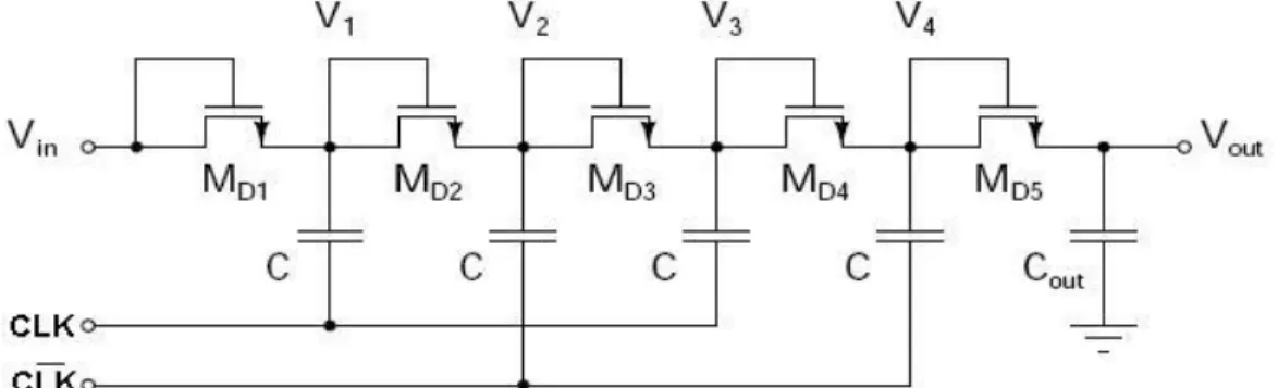
The first voltage multiplier circuit proposed by Cockcroft and Walton in 1932 was composed of a single chain capabilities interlaced switch activated an offset in two clock phases. To improve the conversion efficiency and output impedance, Dickson has developed in 1976 a new architecture based on the same principle of operation. This consists of a number of diodes in series; each node is connected to a capacitor. The other end of the building is controlled alternately by one of two clock phases; φ and φ- (Pylarinos, 2008). The modern version of the chain of Dickson, where the diodes are replaced by diode-connected MOS transistors is shown schematically in Figure 2.8. This architecture is the basis for the majority of the charge pumps today.
Figure 2.8: Dickson charge pump of four stages (Pylarinos, 2008).
When clock phase is high, for example φ = Vφ and φ- = 0, the corresponding capacities are the voltage at their terminals (in this case, V1 and V3) Vφ be increased. At this time, transistors series (MD(2i)) lead the charge transfer from one floor. The next cycle (φ = 0 and φ- = Vφ), then it
is the odd transistors (MD(2i-1)) that lead and so on. The result is a moving load always in the
same direction that is to say to the output Vout. Between each stage, then there is a theoretical increase voltage Vφ – Vth. Taking into account the parasitic capacitance Cp between each stage
and present current Iout dissipated by the output load, the voltage generated at the output
becomes:
(2.1)
where N is the number of stages and fosc is the frequency of the clock (Pylarinos, 2008). It is then
possible to determine the voltage increase AV at each stage of the Dickson’s chain:
(2.2)
As CMOS technologies are more miniaturized, the gap between VDD and Vt and, therefore, increased AV is reduced. In addition, due to the body effect, Vt increases as the voltage increases
at a given stage, which means that AV decreases with N. To overcome these problems, several
changes to the architecture of Dickson have been proposed over time.
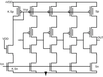
2.3.2 NCP-2 Architecture
First, the diode-connected MOS transistors are added in parallel MDi with another transistor MSi
whose gate is controlled by the output of the next stage (Wu & Chang, 1998). Thus, when the pump starts, MSi is that the load is getting transferred. The threshold voltage Vt is canceled by
the fact that its gate voltage is higher than its drain voltage from the previous stage. This phenomenon, however, ensure that MSi is never completely closed, causing a leakage current. To
solve this problem, the architecture NCP-2, where two other transistors controlling the gate voltage MSi are added at each stage, has been developed (Wu & Chang, 1998) and is shown
Figure 2.9: NCP-2 charge pump of four stages. From (Wu & Chang, 1998)
This circuit was used and slightly modified at the output stage through a peripheral nerve stimulator (Nadeau & Sawan, 2006). Two diode-connected transistors have been added to the end of the chain to raise the control voltage components MSi of the last two stages, thus
improving the transfer efficiency. In the same way, the implementation of a second pair MD/MS
on the top can also be used for the same purpose, such as for circuits PGI-1 and PGI-3 (Hu & Chang, 2006).
2.3.3 Dynamic polarization of the substrate
Another technique improves the load transfer of architecture of Dickson is the dynamic control of the substrate voltage of diode connected MOS transistors (Shin et al., 2000). As shown in Figure 2.10, the NMOS transistors have been replaced by PMOS which are isolated from the substrate in the N-type wells. The bias voltage of the wells may then be controlled dynamically by the other two transistors according to the cycle, significantly reducing Vt by body effect and improving the voltage increase stage by the charge pump.
Figure 2.10: Charge pump with dynamic biasing of the substrate. From (Shin et al., 2000)
2.3.4 Dual path charge pump
It can be noticed that in the architectures presented so far, the output stage receives loads of a half-cycle. To maximize the effectiveness of voltage conversion, an implementation in two independent paths whose clocks are inversed has been implemented (Park & Chung, 2007). Thus, the output stage receives loads in each half cycle, by ensuring that its rise time is faster and that it supports larger output currents. The trade-offs to take advantage of these improvements is the duplication of circuitry.
2.3.5 Pelliconi charge pump
Pelliconi architecture, with one stage is shown in Figure 2.11, is not directly based on the chain Dickson (Pelliconi et al., 2001). Each stage consists of two NMOS and two PMOS which is actually composed of two paths controlled by two clock phases, maximizing the charge transferred per cycle. MOS transistors are used as switches here. This implementation allows you to generate high voltages despite its simplicity.
Figure 2.11: One stage of the Pelliconi charge pump. From (Pelliconi et al., 2001)
2.3.6 Clock doubler charge pump
A clock doubler circuit (Huang et al., 2008) can be introduced at each stage of a charge pump to elevate tensions clocks φ and φ-, always with the aim of eliminating Vt. This strategy has been applied to several different architectures (Yamazoe et al., 2005; Chebli & Sawan, 2007). Figure 2.12 shows the circuit that repeated cascade can also generate a clock whose voltage is very high.