HAL Id: tel-03080963
https://tel.archives-ouvertes.fr/tel-03080963 Submitted on 18 Dec 2020
HAL is a multi-disciplinary open access archive for the deposit and dissemination of sci-entific research documents, whether they are pub-lished or not. The documents may come from teaching and research institutions in France or abroad, or from public or private research centers.
L’archive ouverte pluridisciplinaire HAL, est destinée au dépôt et à la diffusion de documents scientifiques de niveau recherche, publiés ou non, émanant des établissements d’enseignement et de recherche français ou étrangers, des laboratoires publics ou privés.
Processing of PVDF/PMMA Films by Melt-State
Extrusion-Casting : Impact of PMMA on Beta-Phase
Crystallization and Related Piezo/Ferroelectric
Properties
Alexandre de Neef
To cite this version:
Alexandre de Neef. Processing of PVDF/PMMA Films by Melt-State Extrusion-Casting : Impact of PMMA on Beta-Phase Crystallization and Related Piezo/Ferroelectric Properties. Chemical engi-neering. Ecole nationale supérieure Mines-Télécom Lille Douai; Université de Mons, 2019. English. �NNT : 2019MTLD0018�. �tel-03080963�
Processing of PVDF/PMMA Films by
Melt-State Extrusion-Casting: Impact of PMMA on
Beta-Phase Crystallization and Related
Piezo/Ferroelectric Properties
Alexandre DE NEEF
Thesis presented in fulfillment of the requirement for the degree of Doctor in Science (Be) and Molecules and Condensed Matter (Fr)
Academic year 2019-2020
Jury Members:
Prof. Jean-Marie Raquez (promotor) Prof. Jérémie Soulestin (promotor) Prof. Philippe Dubois (co-promotor) Dr. Cédric Samuel (supervisor – secretary) Prof. Roberto Lazzaroni (president)
Prof. Jannick Duchet-Rumeau (INSA Lyon) Dr. Thibaut Soulestin (Arkema-Piezotech) Dr. Ricardo Jiménez Riobóo (CSIC Madrid)
3 Si l’on prend la peine de se poser un instant, et regarder quelque peu en arrière, force est de constater que cette thèse n’est pas l’aboutissement de quatre, mais de six années de travail. En effet, les deux premières années (Master) ont été consacrées à la découverte des fondements de la piézoélectricité des polymères sous la direction du Professeur Philippe Dubois, chef de service du SMPC à l’époque. Par la suite, ma thèse aura été réalisée sous la codirection du Professeur Jérémie Soulestin de l’IMT Lille Douai et du Professeur Jean-Marie Raquez de l’UMONS et dorénavant chef de service du SMPC. En bref, tout un cycle hystérétique dans le milieu académique, ce qui fait donc énormément de personnes à remercier après toutes ces années enrichissantes au sein du secteur académique et plus particulièrement à l'UMONS et à l'IMT Lille Douai. C’est également grâce au financement de ces deux universités ainsi que du projet Européen « Interreg – BIOHARV » que cette thèse a pu aboutir.
Tout d’abord, je ne peux que commencer par remercier le Professeur Philippe Dubois et le Professeur Jean-Marie Raquez, sans qui je n’aurais simplement pas eu la possibilité de me lancer dans cette expérience qu’est la thèse. Malgré mon parcours asymétrique, ceux-ci m’ont fait confiance et m’ont intégré au sein du SMPC afin de réaliser une thèse sur un sujet encore inexploré au sein de l'UMONS.
Ben, merci pour tout ce que tu m’as apporté, autant du point de vue scientifique (je me sens optimisé) qu’au niveau humain. Tes conseils avisés et ta bienveillance m’ont permis de me surpasser à chaque étape de ce long processus. Je vais désormais passer la frontière afin de remercier le Professeur Jérémie Soulestin et le Docteur Cédric Samuel. Vous savez à quel point la phrase qui suit m’attriste, mais ces français-là méritent vraiment leurs deux étoiles. Cédric, un énorme merci pour ton soutien indéfectible en tant qu’encadrant principal. Il y a des personnes qui nous marquent durant un parcours académique, et tu fais définitivement partie de celles-là.
Je tiens également à remercier le service de génie électrique de l'UMONS et tout particulièrement Manu Bury qui m’a permis de me faire la main sur la polarisation haute tension et d’en acquérir les connaissances élémentaires. Le service CHIPs de Materia Nova mérite également mes remerciements.
4
Cette thèse ne fut pas seulement basée sur l’échange de la cotutelle. En effet, de multiples collaborations extra-universitaires ont permis à ce projet d’évoluer grandement.
Au sein de l’Université de Lille, j’ai eu l’opportunité de travailler avec le Docteur Sophie Barrau et le Docteur Grégory Stoclet, alias le magicien de la DRX. À l’Université de Maubeuge, j’ai eu le plaisir de rencontrer Mohamed Ben Achour, qui travaille de son côté sur le PLA piézoélectrique. Merci pour ces échanges enrichissants. Enfin, je tenais à remercier el Doctor Ricardo Jiménez Riobóo pour son accueil au sein de l’Universitad del Autonoma de Madrid. Avec le support d’el Doctor Harvey Amorin, ils m’ont permis de peaufiner mes connaissances sur le comportement de mes matériaux. Muchas gracias !
Je remercie le Professeur Roberto Lazzaroni, la Professeure Jannick Duchet-Rumeau, le Docteur Ricardo Jiménez Riobóo et le Docteur Thibaut Soulestin d’avoir accepté de constituer mon jury de thèse. Merci pour votre intérêt à juger mon travail.
Je tiens à remercier l’ensemble de mes collègues du SMPC et du TPCIM pour les excellents moments passés ensemble. Des classiques dîners en trio avec Mounch et Noémie, aux sorties restaurant/bowling/Doudou/CDM/Noël/JD… avec vous tous, anciens, présents et nouveaux éphémères collègues. Je ressortirai avant tout, l’excellente affinité que j’ai (eu) avec Antoniya, Ameni, Valentina, Lucie, Nicolas, Alexandra, Bastien, Remy, Riccardo et Jonathan.
Mes amis, merci pour ces journées/soirées/nuits passées à se marrer et à jouer aux jeux de société. Nos multiples sorties sportives m'ont permis d'éviter le court-circuit durant ce marathon qu'est la thèse.
Mes sœurs, mes frères merci d'avoir toujours été là pour moi, dans les bons, comme dans les mauvais moments.
Maman, papa cette thèse représente à elle seule tout le travail que vous avez fourni pour que je puisse en arriver-là. Un gosse qui t’empêche de dormir pendant 6 mois, qui te procure 95 % de problème pour 5 % de satisfaction, qui te fait voyager dans tous les sens, etc. Je vous comprends beaucoup mieux désormais. Merci pour tout, infiniment !
À mes Mamys, parties trop tôt pour partager ma joie et ma délivrance. Reposez en paix.
5 « C’est votre attitude, plus que votre aptitude, qui détermine votre altitude. » Zig Ziglar
7
Remerciements ... 3
Chapter I: General introduction ... 11
Chapter II: State of art ... 17
II.1. Ferroelectric and piezoelectric polymers: fundamentals and applications ... 17
1.1. General considerations ... 17
1.2. Ferroelectric polymers ... 19
1.3. Piezoelectric polymers ... 21
1.4. Advanced applications of ferro/piezoelectric polymers ... 23
II. 2. PVDF: Synthesis, crystallinity, processing and properties ... 27
2.1. Generalities ... 27
2.2. PVDF synthesis ... 28
2.3. PVDF crystalline structures ... 29
2.4. Routes to ferroelectric/piezoelectric PVDF ... 33
2.5. Polarization, poling and ferro/piezoelectric properties of PVDF-based polymers ... 37
II.3. Blends based on PVDF ... 43
3.1. PVDF-based miscible blends ... 43
3.2. Case of PVDF/PMMA blends ... 44
3.3. Crystallization of the PVDF beta phase in PVDF/PMMA blends ... 46
8
II.4. General conclusion and challenges ... 53
II.5. References ... 55
Chapter III: Research strategies ... 65
Chapter IV: Processing of PVDF-based Electroactive/Ferroelectric Films: Importance of PMMA and Cooling Rate From the Melt State on the Crystallization of PVDF Beta-Crystals ... 69
IV.1. Abstract ... 71
IV.2. Introduction ... 73
IV.3. Experimental section ... 77
IV.4. Results and discussions ... 81
IV.5. Conclusions ... 99
IV.6. References ... 101
Chapter V: Enhanced Beta Phase Crystallization in Melt-Processed PVDF Films Blended with PMMA-based Copolymers and Impacts on Subsequent Ferro/Piezoelectric Performances ... 107
V.1. Abstract ... 109
V.2. Introduction ... 111
V.3. Experimental section ... 115
V.4. Results and discussions ... 119
V.5. Conclusions ... 143
V.6. References ... 145
CHAPTER I
11
Chapter I: General introduction
During these last years, we are facing up to new smart technologies in the aim to make our daily life easier with an increased energy demand. The ultra-connectivity or global monitoring, commonly called Internet of Things (IoT) (Figure I.1), is one of the faster-growing area that urgently needs to be specifically developed without (or limited) environmental footprint while keeping possible technological breakthroughs and economic growth.
In this context, piezoelectric and ferroelectric materials are among the most emerging players in materials science, driving the development of high technologies in a large range of industrial sectors such as information and telecommunications, healthcare, automotive, aerospace, defense, microelectronics and others. These smart materials have the ability to convert mechanical energy into electrical energy and, unlike other energy sources such as non-renewable fossil energy, mechanical energies represent a renewable and green energy source. Indeed, numerous surrounding mechanical energy sources such as vibrations, shocks and drafts could be converted into exploitable or storable electricity by piezoelectric materials. Piezoelectric energy generation has the merit of being inexhaustible, environmental-friendly, very sensitive, non-harmful, less restricted by the working environment and more importantly economically advantageous.
12
For many years, piezoelectric materials have already been used in many “first-generation” applications such as transducers (ultrasonic, sonar system, ballistic), actuators (vibration controllers, high-precision and small strains), sensors (tactile/haptic systems, accelerometers, pressure/stress/strain/impact gauges), acoustic devices (speakers, headphone, audio-frequency microphone) and electricity generators (high-voltage power sources). In 2019, the worldwide market of piezoelectric materials is estimated to be approximately 1 billion USD (35% for only piezoelectric actuators). For 2024, a potential growth of 6 - 10% is estimated for this first-generation application. However, new smart applications are expected which suggests a much steady market growth for piezoelectrics. More recently, ferroelectric and piezoelectric materials have extended their application fields to photovoltaics (organic photovoltaics), memory applications (FeFET, FeRAM) and microelectromechanical systems (Figure I.2). However, these materials are also expected to play a key role in the field of self-powered wireless sensors (for IoT and healthcare) and energy harvesters/microgenerators devices.
13 The global market of piezoelectric materials therefore begins to grow in the field of "energy harvesting devices". The IoT is certainly one of the most influential triggers and the advantages of piezoelectric energy harvesting devices are the possibility of battery-less, extended lifetime, reduced maintenance costs with, of course, positive sustainable development aspects. IoTs are therefore a new development target for many R&D centers, universities, recent start-ups and numerous key industry players (Samsung Electronics, General Electrics, Hewlett Packard, Xerox, Microsoft Technology, Apple, Ricoh, Fujifilm, Canon, Epson, Merck, Arkema, Honeywell, Boeing, etc.).
Although the field of IoT is booming, piezoelectric and ferroelectric polymer materials have not yet reached their full technological maturity in this field, unlike piezoelectric and ferroelectric ceramics. Indeed, these polymers provide many advantages such as flexibility, stretchability, resistance to chemical attacks and ease of implementation at the industrial scale. Major efforts are still required to overcome current technological challenges through a better understanding of these materials as well as the development of advanced techniques to obtain cost-competitive piezoelectric systems at the material/processing level.
The present PhD thesis is carried out in a context of understanding and mastering the knowledges related to the behavior of piezoelectric polymers processed by melt-state extrusion techniques, which can be applied on an industrial scale. A special emphasis was made on the design of piezoelectric materials based on poly(vinylidene fluoride) (PVDF), PVDF being the most popular piezoelectric polymer. To control the polar crystalline PVDF phase, the blending route was chosen by the addition of poly(methyl methacrylate) (PMMA) as a polymeric partner. This manuscript outline is composed of three main chapters.
The first part presents the state of the art and introduce the current research in the field. The various dielectric behaviors are first reported followed by a mapping of PVDF and its peculiar crystalline properties as well as the interest of the PVDF/PMMA blends.
The fourth chapter is devoted to optimizing the implementation/processing of the PVDF/PMMA blends in order to obtain thin films with enhanced polar beta phase content without pre-/post-treatments. Various advanced techniques have been employed to precisely study the crystallization of PVDF under high cooling rates and different amounts of PMMA. Then, the conditions for obtaining the
14
PVDF polar phase have been gathered in a crystal phase diagram. A second part presents prospective studies carried out to characterize the ferroelectric properties of melt-processed PVDF/PMMA blends.
The fifth chapter proposes the study of the impact of functional PMMA copolymers on PVDF crystallization as well as ferroelectric and piezoelectric properties of PVDF blends. A crystalline study was carried out on melt-processed blends of PVDF and PMMA copolymers in order to observe their impacts on PVDF crystallization. Subsequently, the study of the ferroelectric properties of these blends made possible to identify the most interesting compositions. Finally, the polarization conditions and the piezoelectricity were studied in detail to open up different ways of improvements for PVDF/PMMA blends.
Finally, a general conclusion summarizes the main results obtained during this PhD thesis, as well as some research perspectives in order to improve the performance of the proposed thin non-stretched PVDF films.
CHAPTER II
17
Chapter II: State of art
II.1.
Ferroelectric
and
piezoelectric
polymers:
fundamentals and applications
1.1. General considerations
Traditionally, dielectric materials are derived from inorganic materials such as porcelain1, mica2, and quartz3 (ceramics and crystals) but more interestingly,
polymers can also be used as efficient dielectric materials. They have the advantage of being easily processed and flexible but also finely tailored for various dielectric applications4. The dielectric properties (dielectric constant, dielectric losses, polarizability, etc.) of any polymer depend on their chemical composition and internal structure. Most of dielectric polymers are semi-crystalline polymers and such dielectric polymer materials could present piezoelectric and/or pyroelectric and/or ferroelectric properties depending on their internal crystalline structure and organization.
When a dielectric material is placed under an electric field, an internal polarization is induced inside the material. Induced polarizations includes electronic, ionic, orientational/dipolar, and interfacial polarization5. Each polarization is associated with a dielectric loss at a specific frequency. Dipole polarization, dipole density and occurrence of organized dipole domains are basic phenomenon linked to dielectric behaviors of polymers (Figure II.1).
Linear dielectric polymers6,7, more often just called dielectric polymers is a material with the capacity to be polarized under electrical field in order to store the electrical charge. The resulting polarization P or electrical displacement D is linear with the applied electric field E. This type of material is not influenced by the strength of the electrical field, i.e. 𝑟 (relative permittivity or dielectric constant) is constant8. This can be explained by the fact that a linear dielectric
does not have any net dipole, no dipole coupling capacity and no spontaneous polarization (that quickly returns to zero with removal of electric field). Several polymers display linear dielectric behavior such as poly(ethylene) (PE), poly(ethylene terephthalate) (PET), biaxially-oriented poly(propylene) (BOPP), poly(methyl methacrylate) (PMMA), modified PMMA, poly(phenylene sulfide)
18
(PPS), poly(carbonate) (PC) and poly(ether ether ketone) (PEEK). Thin-film capacitors represent the most common application of these linear dielectric polymers.
Dipolar glasses have similar behavior with isolated dipoles. The interactions between dipoles are weak and no coherent domains are formed. This behavior is essentially observed for ceramics, but Bonardd S. and co. demonstrated in the case of several glassy polymers5,9. With relatively high
dielectric constants and low dissipation factors, the dipolar glassy polymers can be used for energy storage with minimal energy losses.
Figure II.1: Different FE domain structures (compound by dipoles) with
increasing dipole−dipole or domain−domain interactions from left to right (the top panel) and corresponding electroactive responses in D−E loops (the bottom panel).
In the case of high dipole interactions and organization into large coherent domains, a spontaneous/remanent polarization could be observed with potential ferroelectric properties. The dipoles present in these polymers can be arranged upon different dipole sizes and domain structures, as shown in Figure II.1 with charge–discharge responses of typical ferroelectric/relaxor materials. In the following points, their different properties are described.
19
1.2. Ferroelectric polymers
Similar to ferromagnetic materials, ferroelectric polymers10–12 exhibit
spontaneous polarization, i.e., an effective electric dipole moment without external electric field. This spontaneous polarization13 can be reversibly switched by an external field without any change in the domain structure. To characterize the ferroelectric effect, the (D-E) or (P-E) hysteresis loops allow identifying the electric displacement D (or the polarization P) as a function of applied electric field. The resulting polarization D reflects the dipole orientation and the existence of a high spontaneous polarization (at zero electric field, D close to Dmax) with
reverse polarization (as illustrated by a hysteresis loop, Figure II.2) is generally accepted as proof of ferroelectricity.
Figure II.2: Illustration of (A) normal ferroelectric, and (C) paraelectric
behaviors of the high temperature DE phase in poly(vinylidene fluoride-co-trifluoroethylene), P(VDF-TrFE).14
The most well-known ferroelectric polymer is the poly(vinylidene fluoride) (PVDF), but it is rarely used in its natural state. In fact, the ferroelectric crystalline structure is not generally induced during classical processing. A lot of studies have been focused on different ways to promote specifically the ferroelectric crystalline phase. The use of copolymers like PVDF-TrFE is an example and the most common ferroelectric polymer material but there are other polymers15 as the poly(trifluoroethylene) (PTFE), cyano-(co)polymers and poly(vinyl chloride or fluoride) (PVC or PVF). One can mention out that biobased ferroelectric polymers are available on the market, odd-number nylons (PA…)16, poly(ureas) (PU)17,18
20
and poly(lactic acid) (PLLA)18,19. In spite of their interest, they currently have lower ferroelectric properties than PVDF.
Most of ferroelectric polymers undergo a structural phase transition from a high-temperature no-ferroelectric (or paraelectric) phase into a low-temperature ferroelectric phase. This specific transition temperature is called Curie temperature (TC), i.e., the temperature limit for ferroelectric applications. This
paraelectric-to-ferroelectric transition usually leads to strong anomalies in the dielectric, elastic, thermal and other properties of the material20,21 with changes in
the crystal unit cell dimensions and ferroelectric domain sizes (Figure II.2). Several other intermediate dielectric behaviors could also exist depending on the coherent ferroelectric domain size and interactions strengths. Among them, one can mention relaxor ferroelectric and antiferroelectric behaviors. The relaxor ferroelectric (RFE) behavior is a result of random defect insertions into a ferroelectric material. The normal ferroelectric polymer P(VDF-TrFE) is converted into a relaxor ferroelectric22,23 (ex. P(VDF-TrFE-CFE)) thanks to a
chemical approach or in other cases by electron beam irradiation24. A significantly
reduced remanent polarization (at zero electric field) and dramatically improved discharged energy density are obtained. Relaxor polymers show generally strong dielectric constants, low loss dielectric and a low hysteresis, making the relaxor ferroelectric polymers good candidates for energy storage.
An antiferroelectric dielectric behavior is observed with peculiar ferroelectric domains containing two sublattices polarized spontaneously in antiparallel directions or with a ferroelectric phase that can be induced by applying a strong electric field. Experimentally, the reversal of the spontaneous polarization in ferroelectrics is observed as a single hysteresis loop (Figure II.1). The induced phase transition in antiferroelectrics is observed as a double hysteresis loop (Figure II.1), when a low-frequency AC field of a suitable strength is applied. So far, no inherent antiferroelectric crystalline phase has been identified for polymers. These behaviors are still new for semi-crystalline polymers and their fundamental mechanisms have not yet been fully understood. The antiferroelectric behavior with double hysteresis loops has been reported first for β-PVDF at temperatures below −60 °C20 and P(VDF-TrFE) with VDF content
lower than 50 mol%25,26. The double hysteresis loop consists of a dipole
depolarization step at low fields and a polarization reverse step at high fields. It only appears in the first stage a few (D-E) cycles and eventually transforms into a single hysteresis loop upon repeated cycling. Therefore, this behavior is
21 attributed to imperfect P(VDF-TrFE) crystals cooled from the melt with the coexistence of ferroelectric and paraelectric phases25.
Even though antiferroelectric and relaxor ferroelectric behavior are not well-known and controlled, several applications are already expected. With these specificity, they can naturally claim the place in high energy storage capacitors as a defibrillator capacitor or a DC-link capacitor for electric vehicles5 (ex.
PVDF-TrFE-g-PEMA). They also present electrocaloric property, which has a great potential to realize solid-state cooling devices27.
1.3. Piezoelectric polymers
The piezoelectric behavior of polymer is a specific coupling between dielectric and mechanical behaviors of dielectric material. The French physicists Jacques and Pierre Curie discovered the piezoelectricity in 1880. These specific materials have the property to produce electrical charges across their boundaries in response to applied mechanical stress, called the direct piezoelectric effect28. The relationship between induced charges per unit area and the applied
stress is linear and reversible (the reverse piezoelectric effect, the internal generation of a mechanical strain resulting from an applied electrical field).
The nature of the piezoelectric effect for a polymer is closely related to the occurrence of electric dipole moments. The dipole density or polarization (dimensionality [C.m/m3]) may be calculated by summing up the
dipole moments per volume unit of the crystallographic unit cell29. As every
dipole is a vector, the dipole density or polarization P is a vector. Dipoles close to each other tend to be aligned in regions called Weiss domains. These domains are usually randomly oriented but can be aligned using the poling process. Not all piezoelectric materials can/need to be poled.
The quasi-majority of piezoelectric materials in practical use (with the important exception of several materials such as quartz or specific oriented polymers) are ferroelectric. In a ferroelectric material, the remanent polarization could be modified with the applied stress to give rise to piezoelectricity. Every ferroelectric material is piezoelectric but not every piezoelectric material is ferroelectric. Indeed, such effects could also appear when asymmetrical chemical structures are present in the crystalline state or even in the amorphous state30. The
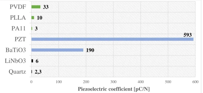
following Figure II.3 shows a non-exhaustive comparison between three main materials having a piezoelectric behavior. Each material has these advantages and drawbacks. For polymers, the value of piezoelectricity is clearly lower than
22
ceramics, but polymers are much easier to be processed (temperature of process, thin film, microfabrication …) and have a better stretching capacity. In this respect, each material will target specific applications.
Figure II.3: Comparison of several piezoelectric materials (polymers, ceramics
and crystals.)
The piezoelectric phenomenon is mathematically formulated with the following equations:
𝑫𝒊 = 𝜺𝒐. 𝜺𝒊 𝒋𝝈 . 𝑬𝒊+ 𝒅𝒊 𝑱. 𝝈𝑱
𝜹𝑰 = 𝑺𝑰 𝑱𝑬 . 𝝈𝑱 + 𝒅𝑰 𝒊. 𝑬𝒊
With electric displacement (D), electric field (E), stress (σ), strain (δ), free space electric permittivity (𝜀𝑜), piezoelectric coefficient (d), material’s electric relative permittivity (dielectric constant) matrix at a constant stress (𝜀𝜎), material’s mechanical compliance matrix at constant electric field (𝑆𝐸). Values from 1 – 6 (direction of the mechanical stress/induced mechanical strain) (I & J). Values from 1 – 3 (direction of the electric polarization/electric field applied) (i & j). Tensors indicating the three-coordinate x, y and z (D & E). Tensors indicating normal stresses or strains (from 1 – 3) and shear stresses or strain (4 – 6) (σ & δ). Piezoelectric coefficients quantify the strength of the piezoelectric effect and various transduction modes are observed depending on dXY, X and Y are the
identification of the axis of polarization and stress direction. Only 3 – 4 piezoelectric coefficients are usually considered. The most frequently used are 𝑑33 (both direction) and 𝑑31 (transverse direction) (Figure II.4).
2,3 6 190 593 3 10 33 0 100 200 300 400 500 600 Quartz LiNbO3 BaTiO3 PZT PA11 PLLA PVDF Piezoelectric coefficient [pC/N]
23
Figure II.4: 33- and 31-transduction modes for piezoelectric materials.
In the specific case of polymers, different piezoelectric categories may be considered as illustrated and explained in details by Harrison31. In the case of this study, only bulk piezoelectric polymers will be considered and especially semi-crystalline piezoelectric polymers. In this case, the piezoelectric effect of this category is due to the molecular structure of the polymer, its semi-crystalline structuration and its orientation.
1.4. Advanced
applications
of
ferro/piezoelectric
polymers
Piezoelectric materials find every-day uses such as the ignition source for lighters, push-start propane barbecues, time/frequency reference sources in quartz watches and amplification pickups for some guitars18,31,32. The
piezoelectric effect also represents the basic phenomena for a number of scientific microscopy techniques with atomic resolution such as scanning tunneling microscope (STM), atomic force microscope (AFM) and scanning near-field optical microscopy (SNOM).
Sensors and actuators are important applications of piezoelectric polymers. Numerous examples are found in the medical field. These materials could be used as sensors33,34 for prosthesis, orthotics or noninvasive cardiopulmonary operations or artificial muscles, as depicted by De Rossi35 and Sheng-Guo34. In the acoustic field, piezoelectric polymers are used for hydrophones36, shock wave sensors,
surface acoustic wave sensors, as depicted by Howarth and Rittenmyer37.
Today, the researches about piezoelectric polymer materials are focusing on specific applications in energy harvesting. The aim is to develop energy harvesters38 from mechanical energy (wind, motion, vibration, strain …) and
24
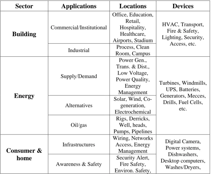
convert it into electricity. Numerous potential applications are thus observed in the field of IoT for piezoelectric polymers as energy sources or sensors. Table
II.1 shows a list of potential sector, applications, locations and devices using
piezoelectric polymers. This table demonstrates that the potential applications for piezoelectric materials are very broad.
It could be also noticed that, in the Internet of Things (IoT) sector, ferroelectric polymers could also be used through the realization of FeRAMs39,
ferroelectric random access memories, using the bi-polarizability as a binary language. The advantages of these non-volatile FeRAMs include fast read/write speed, minimum energy consumption, long cycle life and high flexibility of these polymers (PVDF-TrFE). Note that the robotic based on ferroelectric materials is also a growing sector for medical operations40 and spatial exploration among
others.
Table II.1: Potential IoT applications of piezo/ferroelectric polymers as sensors
or energy harvesting devices
Sector Applications Locations Devices
Building Commercial/Institutional Office, Education, Retail, Hospitality, Healthcare, Airports, Stadium HVAC, Transport, Fire & Safety, Lighting, Security,
Access, etc. Industrial Process, Clean
Room, Campus
Energy
Supply/Demand
Power Gen., Trans. & Dist.,
Low Voltage, Power Quality, Energy Management Turbines, Windmills, UPS, Batteries, Generators, Mecces,
Drills, Fuel Cells, etc.
Alternatives
Solar, Wind, Co-generation, Electrochemical Oil/gas Rigs, Derricks, Well, heads, Pumps, Pipelines Consumer & home Infrastructures Wiring, Networks Access, Energy Management Digital Camera, Power systems, Dishwashers, Desktop computers, Washes/Dryers, Awareness & Safety
Security Alert, Fire Safety, Environ. Safety,
25
Elderly, Children, Power Protection
Lighting, TVs, MP3, game consoles, etc. Convenience & Entertainment HVAC/Climate, Lighting, Appliances, Entertainment Healthcare & Life science Care Hospital, FR, Mobil POC, Clinic, Labs,
Doctor Office MRI, PDAs, Implants, Surgical Equipment, Telemedicine, etc. In Vivo/Home Implant, Home Monitoring Systems Research Drug Discovery,
Diagnostics, Labs Industrial Distribution Pipelines, Mar handing, Conveyance Pumps, Valves, Conveyors, Pipelines, Motors, Drives, Converting, Fabrication, Assembly/Packaging, Vessels/trains, etc. Converting/Discrete Metals, Paper, Rubber/Plastics, Metalworking, Electronics, Assembly/Test Fluid process Retro-Chem.,
Hydro, Carbons, Resource Automation Mining, Irrigation, Agricultural, Woodland Transportation
Non-Vehicular Air, Rail, Marine
Vehicles, Lights, Stops, Signage, Tolls, etc. Vehicles Consumer, Commercial, construction, Off-Highway Trans Systems Tolls, Traffic Management, Navigation, Parking Retail Specialty Fuel Stations, Gaming, Bowling, Cinemas, Discos, Special Events
POS terminals, tage, Cash Registers, Vending Machines, Sings, etc. Hospitality Hotels, Restaurants, Bars, Cafes, Clubs Stores Supermarkets, Shopping Centers, Single Site, Distribution Centers
26 Security & Public Safety Surveillance Radar/Satellite, Environ., Military, Security, Unmanned. Fighters, Battlefields, Jeep, Cars, Ambulances, Homeland Security,
Fire safety, etc. Equipment Weapons, Vehicles, Ships, Aircrafts, Gear Tracking Human, Animal, Postal, Food/Health, packaging, Baggage Public Infrastructure Water treatment, Env./Building Monitoring Emergency Service Equips, Personnel Police, Fire, Regulatory IT & Networks Public Service, E-commerce, data Centers, Mobile Carries, Fixed Carriers, ISPs Servers, Storage, PCs, Routers, Switches, Laptops, etc. Enterprise PP/Data Centre, Office, Private Networks
27
II. 2. PVDF: Synthesis, crystallinity, processing and
properties
2.1. Generalities
Fluorinated polymers such as PVDF with high fluorine contents exhibit high thermal resistance, aging resistance and weather resistance with excellent inertness to solvents, hydrocarbons, acids, alkalines, low surface energy (oil and water repellency), low flammability, low refractive index, and low moisture absorption. Hence, these specialty polymers have found many applications41 in building industry, petrochemical and automotive industries, aerospace and aeronautics, chemical engineering, optics and microelectronics.
PVDF is a semi crystalline polymer having the repeating unit (CH2- CF2)
(Figure II.5). The glass transition (Tg) and melting (Tm) temperatures of the
amorphous and crystalline PVDF regions are in the range of -45/-30 and 155/192 °C, respectively. Physical and electrical characteristics of PVDF have been reported in various reviews42–44, and depend upon the molecular weight,
molecular weight distribution, chain configuration, crystalline form, and chain defects45. Among these properties, PVDF is attractive for its piezoelectric (Kawai46 discovered that behavior in 1969), pyroelectric (first reported in 1971
by Bergman47 et al. and Nakamura and Wada48), and ferroelectric49,50 behaviors.
Figure II.5: Molecular structure of the PVDF
Considering its excellent combination of properties and processability, the PVDF is the second fluoropolymer after PTFE (Teflon), in terms of production volume. Furthermore, its high level of intrinsic crystallinity (ca. 40-60%) results in good mechanical properties (stiffness, toughness and creep resistance). However, PVDF has also two main disadvantages: high melting point (cost of process) and poor solubility in common organic solvent43,44 (only soluble in DMF,
28
2.2. PVDF synthesis
PVDF43 is usually synthesized by a radically-initiated VDF polymerization
in aqueous emulsion or suspension at temperature of 10-130°C under pressures ranging from 10-300 atm (or in supercritical CO251). The reaction is
heterogeneous and the process needs a fluorinated surfactant. Polymerization procedures, temperatures, pressures, recipe ingredients, monomer feeding strategy and post-polymerization processing have a great influence on product characteristics and quality, as discussed in well-documented reviews43,52. However, the synthesis is not safe in conventional conditions, its explosive limit is 5.8-20.3 vol % of VDF in air, for example.
Figure II.6: Free radical vinyl polymerization of the monomer vinylidene
fluoride to obtain PVDF under several chain conformations in the apolar α-phase and in the polar β- and γ-phases.53
As shown in Figure II.6, after polymerization, PVDF adopts different macromolecular conformations, forming specific crystals. As function of the localization of atoms on the carbon chain, the resulting PVDF polymer has different properties and crystallization behaviors. Amorphous phase and crystalline phase differ in their dielectric and elastic properties.
The piezoelectricity in such a material may be due to several effects:
➢ When the material is strained, dielectric constants of the crystalline and amorphous parts may change differently leading to an electro-strictive effect.
➢ The elastic constants of the crystalline and amorphous parts may be different leading to a piezoelectric effect.
29
2.3. PVDF crystalline structures
Researchers have identified at least five different crystal structures for PVDF. The five crystal phases are referred differently depending on the authors, but the most common naming scheme is α, β, γ, δ and . The most frequently studied are α, β, and γ crystal phases54–56. This polymorphism is directly related
to the slightly larger van der Waals radius of the fluorine atom (1.35 Å)57 versus
that of the hydrogen one (1.20 Å). The different conformations are also strongly dependent on processing and electrical, thermal or mechanical treatments that the polymer undergoes. Figure II.7 summarizes different ways of producing the various phases (4) and the transformations between them.
30
A. Alpha phase
The most common polymorph, α phase (form II), having a trans-gauche configuration (TGTG′) (Figure II.8) has a nonpolar conformation of the polymeric chains. Hydrogen and fluorine atoms are alternated in a regular way on both sides of the chain, giving a helical structure58. The helical molecular shape
is much lower in energy than the planar zigzag formation (β-phase), which is most likely why the α phase is readily formed from the melt59. Dielectrically speaking,
it has a dipole moment normal to the chain axis, the molecular chains arrange their dipoles in an antiparallel array, therefore it results a non-polar, centro-symmetric unit cell. Applications, linked to this specific phase, are essentially focused as membranes on chemical industry, construction and biotechnology.
Figure II.8: Crystal structure of the α-phase of PVDF is in the TGTG′
conformation
B. Beta phase
The β crystal60 phase (form I) of PVDF forms a planar zigzag (TT). The
all-trans structure of β phase PVDF forces the fluorine atoms along the carbon backbone to come closer together and overlap their van der Waals radii (Figure
II.9). The simple head to tail organization and planar zigzag structure creates a
very organized crystal. This structure allows tighter packing density and reduces the intermolecular strain allowing greater chain movement. Thermodynamically, it is the most stable phase. The β form of PVDF has superior dielectric permittivity41 thanks to the orientation perpendicular of dipoles to the polymer
31 is thus intrinsically piezo-, pyro-, and ferroelectric. The β-phase is the one with the highest dipolar moment per unit cell (8 × 10⁻³⁰ C.m) when compared to the other phases62.
The amount of head-to-head or tail-to-tail monomers along the backbone determines how easily the β phase will get formed. These imperfections along the carbon chain allow more space between the fluorine atoms and make the β phase more stable. A certain percentage of these HH or TT defects during polymerization decreases the likelihood of β phase formation. Some studies have shown that both HH / TT units are distributed randomly along the polymer chain. The temperature at which PVDF is synthesized, determines the number of head-to-head (HH) and tail-to-tail (TT) units that occur in polymer chains. The percentage of head to head occurring in most commercially available PVDF is approximately 5%.
Figure II.9: Crystal structure of the β-phase of PVDF is in the all-trans
conformation
C. Gamma phase
The intermediate polar conformation (TTTGTTTG′) phase γ (form III) is formed when the polymer is moderately stressed or when high-temperature annealing is applied. This phase is formed during melt crystallization at temperatures above 160 °C and reaches its highest value nearby 170 °C63. The molecular chains are packed in parallel in the non-centrosymmetric, polar crystal (Figure II.10). This form is less known than the other forms and less employed64.
32
Figure II.10: Molecular orientation in the γ-phase
D. Identification of polar phases
In this regard, the β and γ phases are the most electrically active phases, their promotion within the material is an on-going pursuit due to the strong interest in application areas such as sensors, actuators, batteries, filters, chemical warfare protection, magnetoelectric, and, more recently, in the biomedical field65–67.
Different strategies have been therefore developed to obtain the electroactive phases of PVDF, mainly focusing on the development of specific processing procedures and the inclusion of specific fillers.
The two phases of PVDF first discovered were the α and β-phase, which are clearly identified by FTIR and X-ray diffraction62. However, γ-phase has caused some confusion in its identification and has been mistakenly reported as the β-phase68. These mistakes have persisted for a long time and still happen
nowadays due the considerable less attention directed to the properties of the γ-phase69. A careful interpretation of the results provided by the combination of FTIR, XRD and DSC are enough to identify the correct phase of PVDF55,70–76 (Figure II.11 and Table II.2). Indeed, the use of more than one technique is sometimes needed due to the superposition of the peaks of β, γ and α-phases on individual technique.
dddddddddddddddddddddddddddddddddddddddddddddddddddddddddd d
Figure II.11: Characterization by WAXS (a), FTIR (b) and DSC (c) of three
33
Table II.2: Specific WAXS and FTIR values from main PVDF phases WAXS analysis (XRD): Diffraction angle (2θ) FTIR analysis: Wave number (cm-1) α β γ α β γ 17.66° 18.30° 19.90° 26.56° 20.26° 18.5° 19.2° 20.04° 408 523 614 766 795 855 976 510 840 1279 431 512 776 812 833 840 1234
2.4. Routes to ferroelectric/piezoelectric PVDF
As explained above, not all crystalline structures of PVDF are polar but several workers have proposed different methods to enhance the formation of β-phase (Figure II.7). Most of the proposed techniques are based on a β-phase transformation mechanism in homopolymers and copolymers of PVDF77–79 or applying different conditions such as mechanical stretching of the α-phase55,80–83,
high pressure84–86, poling under a high electrostatic field87, ultra-fast cooling88–90,
by addition of nucleating fillers or nanoparticules91–93, hydrated ionic salt94,
blending etc.. Currently, four main procedures commonly employed to promote the beta phase.
A. Stretching
Piezoelectric PVDF films formed in most industrial processes rely on β modification obtained by rolling or drawing of the α-PVDF at elevated temperatures. Starting from the α-phase, stretching is the most employed technique to obtain the β-phase. Conversion of α into β-phase takes place at stretching temperatures in the range of 70 – 100 °C, at a stretching ratio of about 3 – 5 (Lfinal/Linitial). It is seen from the literature81,95 that the critical temperature for
obtaining α-to-β transformation is 140°C. Above this temperature, α-to-β transformation does not occur. Although the mechanical deformation itself introduces some preferred crystallite orientation, it does not affect considerably the orientation of molecular dipoles96. Therefore, the piezoelectricity measured
34
directly after mechanical deformation is still low. Considerable enhancement of dipole orientation leading to high piezoelectricity is achieved by additional polarization of previously deformed material97. It was shown98,99 that the
piezoelectric constant of PVDF samples prepared under the same poling conditions increases with both fraction of β crystallites and degree of crystallinity (influenced by stretching ratio and temperature, Figure II.12).
Figure II.12: d33 coefficient and β-phase content (%) for PVDF with stretching
ratio of R = 5 at increasing stretching temperatures (on left) and for PVDF with increasing stretching ratios R at 80°C100 (on right).
B. Copolymers
Copolymerization is the most common and efficient method to perform effective changes in the main properties for commercial polymers. As a result, copolymerization usually modifies the symmetry of the polymeric chain and modulates both intramolecular and intermolecular forces, so that properties such as melting point, glass transition temperature, crystallinity, stability, elasticity, permeability and chemical reactivity may be varied within wide limits101.
With the aim to improve the PVDF properties and to adapt it to the increasing technological demands, different PVDF-based copolymers have been developed. Poly(vinylidene fluoride-trifluoroethylene), P(VDF-TrFE), is one of the most studied copolymer (Figure II.13).
35 Contrary to PVDF, and under specific molar ratios, it presents always the ferroelectric β crystalline phase. The addition of the third fluoride in the TrFE monomer unit generates a high electrostatic repulsion in the PVDF chain with the consequence to (Figure II.14) favor the all-trans conformation and to induce therefore the ferroelectric β-phase independently of the processing method. This situation occurs when the VDF content is between 50 and 80%102, corresponding
also to the range of the ferroelectric behavior of the copolymer.
Figure II.14: Representations of physical (temporary) and chemical (permanent)
pinning in laterally expanded P(VDF-TrFE) crystals 6. l
1 and l2 are average
interchain distances in PVDF and P(VDF-TrFE) and orange-red ovals with arrows represent dipolar TrFE with larger sizes).
Furthermore, this copolymer presents a Curie Temperature (TC)
significantly below the melting temperature (Tm) depending on the TrFE content
(Figure II.15), contrary to the elevated Curie temperature of PVDF at 195 - 197 °C103,104.
Figure II.15: Phase diagram for P(VDF−TrFE) copolymers of specific
36
As previously said, the TrFE is not the only ferroelectric PVDF-based copolymer, another example is P(VDF-HFP). It consists in the incorporation of the amorphous phase of hexafluoropropylene within the PVDF homopolymer. The presence of ferroelectric properties in this copolymer is strongly dependent on the preparation method of the film (high impact of the amorphous phase from HFP). PVDF has also been modified by the introduction of chloride trifluoride ethylene (CTFE) on the polymer chain, producing the P(VDF-CTFE) copolymer. The introduction of bulky CTFE makes the structure loose, which result in an easier orientation of dipoles under external electric field. The piezoelectric constant, d33 for this copolymer, for example, reaches the value
of 140 pC/N105. Moreover, this type of copolymers has also shown a good
compatibility with the ionic liquids (ILs). Jin Yang et al. 106,107 proposed that the
nanostructuration effect is strongly dependent on the diffusion ability and the dipolar interaction strengths of ILs with P(VDF-CTFE) due to the difference in the chemical structures.
In summary, the copolymerization approach allows promoting the polar phase of PVDF, but there are several drawbacks. Indeed, the realization of a copolymer is related with a much higher production cost, together with a decreased Curie temperature transition, limiting mainly their physical applications.
C. Nanofillers
Some important advances have been obtained in order to unveil the main interactions, driving the nucleation of the electroactive phases of PVDF using specific fillers. The nucleation of the electroactive β-phase in such nanocomposites obtained by melt processing was attributed to the interaction between the negatively charged particles and the polymer CH2 groups, having a
positive charge density108. The electroactive β-PVDF is nucleated by the presence
of BaTiO3 ceramic fillers with a β-phase maximum of ∼80%109. This effect
strongly dependent on the filler size and almost independent of the filler content. The nucleation of the ferroelectric phase is strongly influenced both by geometrical factors due to the nanosize of the fillers and, by interactions at the interface between the local electric field around nanoparticles and PVDF dipoles. Recently, nanoclay and carbon nanotubes have been the main focus as means of enhancing the formation of β-phase crystals in PVDF films. For PVDF-clay nanocomposite, the intensity of reflections characteristic (XRD) of the
α-37 phase decreases with nanoclay content. The peak disappears at nanoclay content of 2–5 wt.% (Cloisite, Montmorillonite, Smectite…).
D. Blends
The ferroelectric and piezoelectric properties of PVDF, can be improved by chemical modification through copolymerization, by the addition of nanofillers to create a composite and by physical modification through stretching, with their own disadvantages. However, another technique as a good potential to improve the piezoelectric/ferroelectric properties of PVDF is solvent- or melt-blending110–
112.
Their properties depend to a large extent on the miscibility of the components. A miscible “mixture” is intimately mixed thanks to thermodynamic forces. The distinct interactions promoting miscibility are delivered by dipole van der Waals interactions or by hydrogen bonding. Thanks to a strong electric dipole in its monomer unit, PVDF is miscible with certain number of polymers having a strong molecular electric moment. Melt-blending is a simple and easy process very interesting from industrial point of view. Knowing the thermal stability problem of ferroelectric PVDF-TrFE, the PVDF-based blending could improve the maximum operating temperature through the enhancement of the structure stability by specific interactions with the additive. Furthermore, the approach can resolve the problem of up scaling of applications at reasonable cost. A specific point is presented below on the blends (II.3. Blends based on PVDF).
2.5. Polarization, poling and ferro/piezoelectric properties
of PVDF-based polymers
A. Generalities
Each PVDF chain has a coupling of positive and negative charges referred to as a dipole. The negatively charged fluorine atoms are coupled with the positively charged hydrogen atoms. The dipoles are rigidly attached to the carbon backbone and their orientation depends on the polymer crystal structure. The β phase has a highly polar arrangement of hydrogen and fluorine atoms. The dipoles along the carbon backbone, and within the crystal, align themselves maximizing spontaneously polarization within the unit cell113,114.
38
The strong dipole formed by the all-trans conformation of the carbon backbone, and parallel arrangement of the chains in the crystalline unit cell create a net charge in β phase structure of PVDF. When β forms naturally the net charge is zero because the dipoles are arranged randomly. However, when a large electric potential is applied across the material, the dipoles align and produce a net positive charge. An example of the dipole alignment can be seen in Figure II.16. Due to this net charge the polymer responds to electrical fields.
Figure II.16: Dipoles alignment relay process in PVDF, random dipoles in blue
and oriented dipoles in red with Ps as saturating polarization, when each dipole is
oriented.115
This dipolar alignment, or poling, must be performed on any piezoelectric polymer before it can be used piezoelectrically. The mechanisms associated to poling are not very well understood. What is known is that crystals within a polymer are influenced by a sufficient electric field and create a net polarization. This net polarization aligns the individual crystals within the polymer causing them to collectively respond to changes in their surroundings and gives PVDF its strong piezoelectric characteristics.
Poling is a group of widely used techniques to reorient the polymer with the aim of increasing the net polarization116 vector in the 3 directions (opposite to the electrical field, direction 1). Usually, poling is undertaken using an electric field applied (from DC or AC current) along the thickness axis of the piezoelectric material at elevated temperatures32. The two most common methods of poling are
electrode and corona techniques, which are shown schematically in Figure II.17
(a and b). Electrode poling is simple, as it only requires electrodes (coated) on
both sides of the film, as shown in Figure II.17 (a). The enclosure can be filled with an insulating fluid or in a heated vacuum to avoid breakdown of the polymer. Intimate contact between the polymer surfaces and the electrodes is required to achieve, in the β phase of PVDF, enhancement of dipoles polarization32.
39
Figure II.17: Schematic of poling systems for piezoelectric polymers, (a)
electrode method and (b) corona poling method.116
Poled ferroelectric materials117 are characterized by the remanent
polarization (the amount of polarization remaining after the poling field is removed, PR) and by the coercive field (the field required to flip half of the
previously induced remanent polarization so that the net remanent polarization is zero, Ec). Remanent polarizations of up to 50-75 mC/m² and coercive fields of
100 to 120 MV/m are typical of PVDF. To characterize these properties which allow to identify the importance of ferroelectricity, the Sawyer-Tower method118,119 is necessary. It gives the hysteresis loop117 of the polarization/dipole displacement as a function of the applied field (Figure II.18) and obviously others values such as the current density.
Figure II.18: Current/Voltage loop (left scale) and polarization/voltage hysteresis
loop (right scale) for PVDF, 10s cycle time, with the poling, resistive, and capacitive terms removed. The remanent polarization is defined as the polarization at zero field (PR) and the coercive field as the field at which the
polarization is zero (Ec).117
PR
Pmax
40
B. Impact of polarization conditions
The degree of polarization is correlated with applied voltage until a saturation level. The same polarization response can be achieved at any temperature, but poling time increases at lower temperatures (usually below 70°C) and can produce a non-uniform distribution within the film. The best uniformity is achieved by applying electric fields for an extended period at temperatures above 90°C. The polarized β-phase is stable and the decay of polarization is only significant at temperatures above 140°C120–123.
The hysteresis loops of β-PVDF show increasing polarization with applied field (Figure II.18). It demonstrates increasing dipole rotation and orientation in the crystalline regions97. It has been pointed that the amorphous region also
contributes to the electroactive behavior of the material124. The piezoelectric coefficient d33 of PVDF films dependence on poled electric fields were shown in
Figure II.19 and was shown clearly the typical relation between the efficient
polarization (here, represented by Ec ± 120 MV/m) and the related
piezoelectricity.
Figure II.19: Piezoelectric coefficient d33 dependence on poled electric fields of
PVDF film (with Boltzmann distribution function)125
However, the hysteresis loops obtained in low β-phase content material are attributed to contributions of trapped charges induced during poling124,126, as the
α-phase material does not show conditions towards switching. The degree of crystallinity has been proposed to affect the shape of the ferroelectric loops, leading to rounded loops for polymers with low degrees of crystallinity127,128.
41 A phase transition125 of PVDF films from α crystal phase to β crystal phase was obtained at 95°C under an electric field of 150 MV/m. The movement of hysteresis implied that the non-polar α phase transited to the polar β phase under increased poled electric fields. Structural changes caused by electric field were probably due to internal rotation of molecule chains and alignments of intrinsic dipoles in crystalline phase of PVDF polymer films. The applied electric field resulting in all-trans planar zigzag conformation was induced into the β crystals. This allowed the dipoles on the polymer chains to align from normal to the direction of the applied poled electric field.
43
II.3. Blends based on PVDF
3.1. PVDF-based miscible blends
Unlike other crystalline polymers, PVDF exhibits miscibility with other polymers such as poly(methyl methacrylate) (PMMA) over a wide range of blend compositions129, where this characteristic can be useful in the fabrication of
membrane with the desired properties. Poly(vinylpyrrolidone) (PVP), poly(ethylene glycol) (PEG) and poly(methyl methacrylate) (PMMA) are the three main polymer partners for PVDF. However, PVDF/PMMA are the mostly used PVDF-based blends because PMMA provides an intense miscibility with the PVDF matrix130,131.
The use of PVDF-based blends as membranes132–137 is clearly the most
important application. Comparing with other materials such as poly(sulfone) (PS), poly(ether sulfone) (PES) and poly(imide) (PI), PVDF is relatively more hydrophobic (linked to its surface tension). PVDF remains the best option of membrane material because it does not dissolve in common organic solvents and, by possessing low level of extractables, PVDF can be considered as a pure polymer which makes it a suitable candidate in biomedical and bio-separation applications. A 50/50 PVDF/PMMA composition is clearly beneficial with better permeation than comparable membranes of similar mean pore sizes.
Another current trend in PVDF-based blends is their use in battery applications. For example, PVDF/PMMA blend microporous membranes were used in an electrolyte liquid to form polymer electrolytes. The use of PMMA changes the membrane morphology from cellular to network structure and causes an increase of electrolyte uptake and ionic conductivity of blend membranes. Proton exchange membrane fuel cells (PEMFC) also utilize such type of membranes. The PVDF-based blend (PVDF/PET/GR) is implemented to obtain a bipolar plate for fuel cells, holding a great promise for use as an environmentally friendly power source for future transportation technology. It can be highlighted applications as polymer electrolytes for dye-sensitized solar cells (PVDF-PMMA-EC-I2).
In brief, the PVDF-based blends are used for many membrane applications, but piezoelectric properties and linked applications were rarely studied and developed. The PMMA is one of the most blended with PVDF due to the high miscibility and the good complementarity between both properties.
44
3.2. Case of PVDF/PMMA blends
The miscibility of PVDF/PMMA blends has been studied extensively since the 1970s. These blends have been found to be completely miscible over the entire range of compositions above the PVDF melting temperature (Tm) of 170 °C and
below lower critical solution temperature (LCST) of 330◦C. According to most studies138,139, PVDF can crystallize in the blend if its weight fraction in percent
exceeds 50 wt-% PVDF (Figure II.20). The miscibility of these two polymers has been evaluated through the transparency of the blends, the Flory–Huggins interaction parameter, the glass transition temperature and so on140. Some researchers confirmed that PVDF/PMMA is miscible regardless of PMMA configurations141–143 (syndiotactic, atactic or isotactic PMMA configurations).
The DSC thermogram shows that the melting temperature of PVDF/PMMA blends decreases with the PMMA content in the blend. For instance, the Tm of
PVDF/PMMA blend is 170 ºC for 30 wt-% PMMA blends. Figure II.20 shows that the blend with 30% of PMMA exhibits two crystallizations peaks. This phenomenon is explained in the literature by the melting of two distinct populations of crystals. In fact, the β crystals melt at a higher temperature than α crystals144,145.
Figure II.20: DSC thermograms of PVDF/PMMA blends (heating cycle on left
and cooling cycle on the right)146
The decrease of crystallinity (enthalpy) and melting point are indicative of the good affinity and miscibility between PVDF and PMMA polymers. Besides, it is well-known that the PMMA is largely amorphous and does not contribute to the heat of melting. In fact, the decrease of Tm in the different blends with the
45 addition of PMMA is explained by the thermodynamic effect, which occurs in a crystalline diluent blend, valid in the case of crystalline polymer-amorphous polymer system146. Nishi and Wang142 concluded that the miscibility
between PVDF and PMMA is stereoselective.
From FTIR analysis, it is observed that, the elongation frequency at 1721 cm-1 of PMMA carbonyl group (C = O), is shifted to higher wavelengths (1724
cm-1) in the PVDF/PMMA blends. This shift is due to the specific interactions
between the carbonyl group of PMMA, on the one hand, and the CH2 group of
PVDF, on the other hand. This finding is indicative of the formation of a miscible blend confirmed by the results reported by Colemann and Painter147 for PMMA/PVDF blends. The presence of a band at 882 cm-1 in the spectrum of the
melted blend indicates that trans sequences of poly(vinylidene fluoride) (PVDF) in the melt state can increase upon PMMA addition. PVDF all-trans conformation allows more efficient interactions with PMMA, which are energetically more stable than the trans-gauche (TG) conformation148.
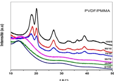
In order to confirm the impact of the PMMA in the crystalline phase of PVDF, a wide-angle X-ray diffraction analysis (WAXS) has been performed on different PVDF/PMMA blends. In Figure II.21, it has been found that the peak at 46,43° (identified as α-phase) and at 20,10° (β-phase), disappears when the PMMA proportion is higher than 30 wt-%. Beyond this, they are no longer found in the spectrum and the amorphous curvature becomes more and more obvious as the proportion of PMMA increases. The progressive decrease of 20.10° peak (without disappearance) shows that the matrix always present crystals of the β phase of PVDF up to a PMMA content of 30%. This observation illustrates the high level of interactions between the two polymers. Furthermore, the decrease in the PVDF crystallization with the addition of PMMA can also be explained by the fact that the diffusion of PVDF towards the crystalline surface, would have been impeded by the interactions with PMMA145,149–153.
46
Figure II.21: WAXS patterns of PVDF/PMMA blends146
From the morphology viewpoint, using the UV–visible absorption spectra of PMMA/PVDF blend, the shape absorption edge (around 240 to 290 nm) shows a shift in band edges toward the higher wavelengths. These shifts indicate the formation of inter/intra interactions between PMMA and PVDF. The shift in absorption edge in the films reflects the variation in the optical energy band gap, Eg. The optical energy band gap decreases with increasing PMMA content. The
existence and variation of optical energy gap, Eg, may be explained by the
occurrence of local crosslinking within the amorphous phase of PMMA and PVDF.
3.3. Crystallization of the PVDF beta phase in
PVDF/PMMA blends
As explained in the previous chapter, PVDF has several types of crystalline form (α, β, γ etc.). The addition of PMMA tends to promote crystallization in β-phase. This is one of the most promising polymer pairs that has been reported to be compatible over a range of compositions in the solid state.
PMMA addition is responsible for the preferential formation of the β-phase upon quenching the molten blends. The drastic reduction of the crystallization rate upon addition of PMMA is a cause, which favours the formation of the β crystalline phase, reported by Hsu and Geil88. Indeed, the significant decreases in the rate of crystallization of PVDF upon the addition of a compatible amorphous polymer with a high glass transition temperature can be recommended as one of