HAL Id: hal-01700742
https://hal.archives-ouvertes.fr/hal-01700742
Submitted on 24 May 2018
HAL is a multi-disciplinary open access
archive for the deposit and dissemination of sci-entific research documents, whether they are pub-lished or not. The documents may come from teaching and research institutions in France or abroad, or from public or private research centers.
L’archive ouverte pluridisciplinaire HAL, est destinée au dépôt et à la diffusion de documents scientifiques de niveau recherche, publiés ou non, émanant des établissements d’enseignement et de recherche français ou étrangers, des laboratoires publics ou privés.
Co-pyrogasification of Plastics and Biomass
Chantal Block, Augustina Ephraim, Elsa Weiss-Hortala, Doan Pham Minh,
Ange Nzihou, Carlo Vandecasteele
To cite this version:
Chantal Block, Augustina Ephraim, Elsa Weiss-Hortala, Doan Pham Minh, Ange Nzihou, et al.. Co-pyrogasification of Plastics and Biomass: a Review. Waste and Biomass Valorization, Springer, 2019, 10 (3), pp.483-509. �10.1007/s12649-018-0219-8�. �hal-01700742�
1
Co-pyrogasification of plastics and biomass, a review
C. Blocka, A. Ephraimb, E. Weiss-Hortalab, D. Pham Minhb, A. Nzihoub, C. Vandecasteelea
aUniversity of Leuven, Department of Chemical Engineering, Celestijnenlaan 200F,
3001 Belgium
bUniversité de Toulouse, Mines Albi, CNRS, Centre RAPSODEE, Campus Jarlard,
Route de Teillet, F-81013 Albi Cedex 09, France
Abstract
Over the past few decades, the sharp rise in post-consumer plastic and biomass waste has resulted in an ever growing challenge to treat such waste sustainably. Co-pyrogasification of plastics and biomass mixtures, as opposed to separately converting these waste streams, offers several advantages including an improvement in syngas quality and composition (H2/CO ratio)
in relation to the desired application, and an easier reactor feeding of plastics. Furthermore, many studies have shown that co-pyrogasification promotes the conversion of waste to gas rather than char and tar. However, in order to achieve the desired product distribution or syngas composition, operating parameters such as the reactor temperature, equivalence ratio (air or oxygen), steam/fuel ratio and catalyst, have to be optimized. Thus, this paper aims to review literature studies on the co-pyrogasification of plastics and biomass by considering various aspects including the process principle, reactors, influence of feedstock characteristics and operating parameters on the products, as well as the synergies observed during the thermoconversion of plastics and biomass mixtures with some reference to coal mixtures when necessary.
Keywords: Biomass, Plastics, Co-pyrogasification, Waste, Waste management
1. Introduction
The annual worldwide production of plastic materials mainly from fossil fuel increased from 1.7Mt/y (1.7 109 kg/y) in 1950 to 322 Mt/y in 2015 [1]. China (27.8%) was the largest producer
in 2015, followed by the rest of Asia (incl. Japan) (21.0%), Europe (18.5%) and NAFTA (18.5%) [1]. In Europe (EU28 + NO, CH) plastics production amounted in 2015 to 58 Mt/year [2] and 25.8 Mt (2014) of post-consumer plastics waste was generated. Treatment of postconsumer plastic waste is thus an important and growing challenge. The 7 most common plastics are, with between brackets the % of European plastics demand for each polymer in 2014 (plastics Europe, 2015): polypropylene (19.2%), PP or (C3H6)n; low-density polyethylene
(17.2%), LDPE or (C2H4)n; high-density polyethylene (12.1%), HDPE or (C2H4)n;
polyvinylchloride (10.3%), PVC or (C2H3Cl)n; polyurethane (7.5%), PUR or C17H16N2O4;
poly(ethylene terephthalate) (7.0%), PET or (C108O4)n; and polystyrene (7.0%), PS or (C8H8)n.
The EU recommends a waste treatment hierarchy with the following order of preference [3]: preparing for reuse > recycling > recovery > landfill
Manuscript Click here to download Manuscript 9 jan2018 article plastic biomass.docx
2
To date, in many countries landfill is still the first option for disposal of postconsumer plastics waste; in the year 2014, 38 % of the plastic waste was landfilled in the EU [4] whereas 68.5 % was landfilled in the US [5]. A landfill ban exists however in Switzerland, Austria, The Netherlands, Germany, Sweden, Luxembourg, Denmark, Belgium and Norway, so that landfill is negligible in these countries. Value (material, energy) can be recovered from postconsumer plastic waste by the following treatment routes [6], [7]:
Mechanical recycling, in which end-of-life plastic waste is used as feedstock to manufacture plastics via mechanical means. The treatment may include size reduction, separation of contaminants and of other plastics, milling, washing, drying. The more complex and contaminated the waste, the more difficult is mechanical recycling. It is therefore the preferred recovery route for homogeneous and relatively clean plastic waste, provided end markets exist for the recyclate.
Chemical or feedstock recycling, whereby plastics are converted into smaller molecules (plastic monomers, syngas), suitable for use as feedstock for the production of the original or other products. The most important technologies for feedstock recycling are pyrolysis and gasification (pyro-gasification). Pyrogasification has the advantage that it can be applied for many sorts of plastics, but also for biowaste, wood….. In each case syngas is obtained, which can be combusted to generate electricity. It is however preferable to use the syngas obtained from gasification to produce various chemicals (H2, methanol, ammonia, urea) and also fuels (e.g. Fischer-Tropsch diesel). Feedstock
recycling (and particularly pyrogasification) has greater flexibility and is more tolerant to impurities than mechanical recycling, but is capital intensive.
Energy recovery. The waste can be combusted to produce energy in the form of steam, heat and/or electricity. Alternatively, the waste can be gasified to give synthesis gas (syngas), which can be used to generate steam via combustion boilers, or, after removal of particles and tar [8], [9], to produce electricity in a gas engine, or, for high efficiency electricity production, in a gas turbine or fuel cell [10].
In 2014 in Europe 29.7% of postconsumer plastic waste was recycled (by far the most by mechanical recycling, in 2012 only 0.3% went to feedstock recycling [11]; 39.5% went to energy recovery; 30.8 % was landfilled) [1]. This would appear a rather positive situation, but it should not be forgotten that much of the plastics collected in the EU in view of recycling or energy recovery are in fact exported to China, where their fate is less certain [12].
Pyro-gasification is feedstock recycling, if the gas obtained is used for producing materials from plastic waste; it must be classified as recovery if the gas (or oil) is used for producing heat and/or electricity (or as biofuel). A lot of potential remains for pyro-gasification (both as feedstock recycling or as energy recovery) of plastic waste, as this would reduce the volume of material sent to landfill thus saving landfill space, and allow valorization as material or energy.
Pyro-gasification (with air, pure oxygen, steam and carbon dioxide or their mixtures as gasifying agent) of pure plastics is treated in many publications: Xiao et al., 2007 [13], Ongen, 2016 [14], Toledo et al., 2011 [15], Erkiaga et al. 2013 [16], Wu and Williams, 2010 [17], Acomb et al., 2014 [18], Wilk and Hofbauer, 2013 [19], Kannan et al., 2013 [20], Cho et al., 2013 [21], [22], Cho et al., 2014 [23], Lopez et al., 2015 [24], Arena et al., 2011 [25], Arena and Gregorio, 2014 [26], Kim et al., 2011 [27], Lee et al., 2013 [28], Salbidegoitia et al. 2015 [29]. Pyrogasification of mixed plastics is treated by Friengfung et al., 2014 [30], Martinez-Lera et al., 2013 [31], Saad and Williams, 2016 [32]. It is clear that pyro-gasification as waste treatment method does not so much target pure plastics, or plastics that can easily be purified, as these are preferably treated by mechanical recycling, but rather mixed plastics and plastics mixed with or contaminated by other waste.
3
in bed material are related to the product composition and the reactor technology. Plastic waste degradation may pollute bio-oil or syngas with corrosive and toxic components (HCl, benzoic acid, tar and so on) that will lower the industrial potential of the technologies. Regarding reactor technology, it should be carefully designed for suitable feeding, mass and thermal transfers [24], [33]–[36]. Moreover, operational problems may occur with plastics gasification, relative to plastics feeding, and in an air blown bubbling fluidized bed, relative to agglomeration of the bed material [24], [33], [34].
Biomass or waste biomass is a suitable feedstock for pyro-gasification, and one of the favorite feedstocks in literature [37]–[44]. An advantage of pyro-gasification (like for other thermochemical conversion technologies as combustion and pyrolysis) is that almost any type of biomass may be used as feedstock, including wood waste from industry or from MSW, agricultural residues, forestry residues, byproducts or waste from the food or feed industry and from the bio-industry, and organic municipal waste. The ideal feedstock for pyro-gasification is not so much pure biomass e.g. wood or food waste, where many other possibilities exist for use or recycling (construction, furniture, fiber panels for wood and wood waste; feed for food waste) or for energy recovery (pellets for central heating, for CHP, etc.). According to Eurostat data (Eurostat, 2012), in 2011 the production of roundwood, including wood and wood waste, accounted for 429 million m3 for the 27 countries in Europe in 2011. Among this roundwood it could be assumed that 10-15% is wood waste. In the US, the availability of biomass is unequally distributed over the country and represents 408 million tonnes dry/year (7.5% of urban wood waste: MSW wood, tree trimming waste, construction/demolition wood) [45]. Taking into account the wood density, this value is quite the double of the roundwood availability in Europe. Regarding wood waste, the classification proposes 4 classes: grade A (clean wood, wood from pallets, packaging, and so on); grade B (industrial wood processing, including construction, demolition, furniture materials and so on); grade C (fuel grade, this is composite of wood, rubber, paint and so on, such as MDF, chipboard) and grade D (hazardous wastes contained metals impregnated and treated woods).
Co-gasification of plastics and biomass allows to improve the quantity of the syngas, as well as its composition (e.g. H2/CO), thus increasing compliance with subsequent applications [46].
Additional motivations for co-gasifying biomass and plastics are [34] :
- It helps to overcome difficulties of seasonal biomass availability [46], [47].
- Increasing the fraction of plastics in a biomass-plastic feed, during steam gasification, would increase conversion of the fuel to gas, and reduce the production of char and tar [24], [48].
- It allows plastics to be fired in a downdraft gasifier [49].
- The operational problems mentioned earlier relative to pyro-gasification of plastics alone can also sometimes be solved by co-gasification of plastics and biomass [33], [46]. Robinson et al., 2016 [34] showed e.g. that, when an air-blown bubbling fluidized bed was fed with composite wood/PET pellets (50/50) problems with coking were prevented. This would be due to a better thermal transfer and fluidization using the composite pellets since the density difference between wood (0.3 to 0.7 g/cm3) and PET (1.35 to 1.38 g/cm3) is significant. Taking into account the different densities of the raw materials, pelletization will tend to improve reactor processing, especially in fluidization technology. However, pelletization using additive, as used by Robinson et al. 2016 [34], may introduce organic and/or inorganic elements that could act as inhibitors or catalysts of the pyro-gasification process, or may introduce pollutants in the syngas.
- Co-gasification may be the method of choice for packaging waste consisting of plastics together with wood, paper, or cardboard and difficult to separate from it.
4
- Brachi et al. also mentioned that the use of biomass and polymeric fuel blends (PET and tyre blends) has proven a useful strategy for overcoming the limitations and operational problems related to using only polymeric fuels, such as the tendency of plastics to become viscous and sticky when heated, the seasonal availability of some types of biomass, e.g. olive husk, nut shells and grape residues, and the low energy density of biomass. They also claim that co-gasification of PET and wood enables a product gas composition such that no further conditioning in a water-gas shift reactor is required in view of downstream methanol production, thus simplifying the overall process.
Robinson et al., 2016 [34] suggested a nice application for small, remote communities: non-biodegradable plastic waste, such as water bottles or plastic food containers are targeted and diverted from the community landfill, and co-gasified with biomass, in the form of composite pellets. The combustible gases can be used to generate power, in order to replace power supplied by diesel engines, which were so far the only way for power production in the considered remote locations and resulted in high electricity prices.
There exists a significant amount of literature on pyro-gasification of mixes of different sorts of biomass, with one type of plastic, with plastics mixes, etc., a large part of which appeared in the last few years, but we do not know a review paper on this topic. The present paper will review this literature, in a broad sense: sometimes coal is added to plastics-biomass mixes, and several papers also consider mixtures of coal with plastics. When these papers are relevant for the present discussion, they will be included. The review paper will compare the behaviour of the mixtures with that of the pure components. Particular attention will be paid to the product yield and distribution (amounts of gas, solid residue and liquid obtained), and to the composition of the gas mixture, all this in relation to potential applications of the products obtained.
The purpose of generating producer gas or syngas is of course its subsequent application. The syngas generated may contain several components, which can cause serious problems (fouling, clogging, corrosion, catalyst poisoning, etc.) during subsequent use of the syngas. Table 1 summarises for each relevant syngas contaminant, the emission concentration in waste gasification, the concentration limit for each application, and the concentration limit of the EU emission standard. It is clear that for all relevant parameters, the limits set by the quality requirements of the applications are, in general, lower than the emissions. Two-step oxidation where the syngas is combusted to produce heat, used to drive an externally fired cycle is relatively insensitive to syngas quality, but the emission of pollutants is a major environmental issue and the results should comply with the EU emission standards [50].
Table 1: Main syngas contaminants with their emissions in waste gasification and the target levels of the major applications [36], [40]-[42]. Contaminant mg/Nm3 Waste gasification Gas engine Gas Turbine Methanol synthesis FT synthesis EU emissions standards* Particulates 104-105 <50 <5 <0.02 n.d. 10 Tar 0-20000 <100 <10 <0.1 <0.01 n.s. Sulphur (H2S, COS) 50-100 <20 <1 <1 <0.01 50 (SOx) Nitrogen (NH3, HCN) 200-2000 <55 <50 <0.1 <0.02 200 (NOx) Alkali metals 0.5-5 n.s. <0.2 <0.2 <0.01 n.s. Halides (HCl) 0-300 <1 <1 <0.1 <0.01 10 Heavy metals 0.005-10 n.s. n.s. n.s. <0.001 0.03 (Hg)
5 Dioxins/furans
ng-TEQ/m3
n.s. n.s. n.s. n.s. n.s. 0.1
n.d.=not detectable; n.s.=not specified; *=at 11% O2
When pyro-gasification is followed by downstream synthesis, in addition to the maximum values for contaminants given in Table 1, a specific composition of the syngas is required, e.g. for methanol production 71% of H2 and 19% of CO are required (Table 2). Also the total
concentration of inert gases (N2, and Ar) must be as low as possible, typically below 2%. These
inert gases are not really toxic for the synthesis, but they reduce the partial pressure of the reactants in recycle processes [41].
Table 2: Main gas composition specifications for selected applications [41], [51], [52]
Synthesis H2 for
refinery
Ammonia Methanol
Fischer-Tropsch Oxo – alcohols H2 >98% 75% 71 60 60 CO <10-50 ppm CO+CO2 <20 ppm 19 30 40 CO2 <10-50 ppm CO+CO2 <20 ppm 4-8% N2 25% Inert N2, Ar, CH4 balance Ar, CH4 as low as possible N2, Ar, CH4 as low as possible CO2, N2, Ar, CH4 low H2/N2 3 H2/CO 1.5-3 1-1.5 H2/(2CO+3CO2) 1.3-1.4 Process temperature 350-550°C 300-400°C 200-350°C 85-200°C
Process pressure >50 bar 100-250 bar 50-300 bar 25-60 bar 15-350 bar
To bring the produced syngas in line with the requirements Tables 1 and 2, gas treatment is required, including gas purification, where contaminants are removed that would otherwise interfere with the subsequent use of the syngas (Table 1), or conditioning where undesirable major gas components are removed or converted, and the ratio of the relevant main components is adjusted to the appropriate value. The water gas shift reaction allows e.g. to convert CO in CO2 and H2 upon addition of steam. Tar is one of the most critical components
and its removal is essential for syngas application. Recently several review papers were published on tar removal or reduction from syngas from biomass or plastics pyro-gasification [8], [9], [53]–[55]. It is clear that each purification or conditioning step makes the process more complicated and more expensive. Therefore it would be ideal if one could approach as much as possible the required specifications, without further treatment steps. There exist traditional primary measures that can be used to modify the ratio of main components in the syngas and
6
to remove tar. These consist in optimising the gasifier configuration and the operating conditions (temperature, equivalence ratio, pressure, gasifying agent, additives or catalysts in the bed). In addition we believe that selecting a suitable plastic, biomass and plastic/biomass ratio allows also to approach the desired gas composition. Therefore the paper will subsequently discuss the influence of the feedstock, the gasifying agent, the temperature, the equivalence ratio, and catalysis.
2. Pyro-gasification
2.1.Principle, gasifying agents and reactions
Pyro-gasification is a thermal treatment usually including the following steps: drying, pyrolysis or devolatilization, char gasification, and (partial) oxidation. There is no sharp boundary between these different steps, they often overlap. The term pyro-gasification is used as we do not only consider the gasification step, but we include also the pyrolysis step, and it is difficult to distinguish pyrolysis and gasification, as ‘pyrolysis’ under N2 gas will also give gasification
products because of the water (moisture) and oxygen present in the feedstock and in the feedstock molecules. The feedstock, which in the case of biomass contains typically 10 to 20% of water, is first dried and then undergoes pyrolysis or devolatilization. This occurs in the absence of oxygen gas and at temperatures between 300 and 800°C. The products of pyrolysis may be classified into three principal types, the relative yields of which depend on the heating rate, the pyrolysis temperature, the residence time in the reaction zone and the composition of the waste [56]:
Solid (mostly char)
Liquid (tars, heavy hydrocarbons, oil, water)
Gas (CO2, H2O, CO, C2H2, C2H4, C2H6, C6H6, etc.).
Secondary reactions may then take place involving the volatile products.
A low heating rate, a high temperature and a long residence time favour conversion to char; similar conditions but with a longer residence time conversion to gas; and finally fast heating, intermediate temperature and short residence time favours conversion to oil [57]–[59]. For biomass, high lignin tends to increase the char yield, high cellulose and hemicellulose the gas and oil yields [60], [61].
Pyrolysis is followed by gasification, which can take place in the same reactor or in a subsequent one, the overall process will be called pyro-gasification. Gasification takes place at high temperature (the heat being supplied directly or indirectly), ranging from 500 to 1500°C, and requires a gasifying agent like air, pure oxygen, steam, carbon dioxide or a combination thereof. Under these circumstances, the large molecules are further converted into lighter molecules and eventually into permanent gases (CO, H2,CO2, CH4, and light hydrocarbons),
tar, char, and ash. Tar and char result from incomplete biomass conversion. The final gas product is either:
- producer gas, a mixture of gas produced by gasification at relatively low temperature, 700 to 1000°C, and composed of CO, H2, CO2, CH4 and trace amounts of higher
hydrocarbons, inert gases from the gasifying agent and other contaminants e.g. char particles. It is usually combusted in a boiler for heat, or in an internal combustion gas engine to generate electricity or combined heat and power, and the heating value depends on the type of gasifying agent and gasification process;
- (bio)syngas (synthesis gas), a mixture of CO and H2, which after clean-up to remove
impurities can be used as feedstock for the chemical industry to produce organic molecules.
7
For simplicity we will speak of syngas or product gas, and will not distinguish between both. Key reactions that occur in gasification are, depending on the gasifying agent:
C + H2O CO + H2 H0298 = +131 kJ/mol (1) (primary water gas reaction)
C + CO2 2 CO H0298 = +173 kJ/mol (2) (Boudouard reaction)
CO + H2O CO2 + H2 H0298 = - 42 kJ/mol (3) (water gas shift reaction, WGS)
The carbon in the reactions refers to the char generated by earlier pyrolysis. Reactions (1) and (2), as well as the combination of (1) and (3), the secondary water gas reaction, are highly endothermic.
To provide the heat for drying, pyrolysis and gasification, some exothermic combustion is allowed by injecting air or pure oxygen, the most important oxidation reactions being:
C + 0.5 O2 CO H0298 = -111 kJ/mol (4) (partial oxidation) CO+ 0.5 O2 CO2 H0298 = -283 kJ/mol (5) (complete oxidation) CH4 + 2 O2 CO2 + 2 H2O H0298 = - 803 kJ/mol (6)
H2 + ½ O2 H2O H0298 = -242 kJ/mol (7) All these reactions with oxygen are moderately to highly exothermic. Other reactions of importance in pyro-gasification are:
CH4 + H2O CO + 3 H2 H0298 = 206 kJ/mol (8) (steam reforming) CH4 + CO2 2CO + 2 H2 H0298 = 247 kJ/mol (9) (dry reforming)
C + 2 H2 CH4 H0298 = - 75 kJ/mol (10) (hydrogasification or methanation)
CnHm + n H2O n CO + (n+m/2) H2 (11) (steam reforming of heavy hydrocarbons
and tar)
Reactions (8) and (9) show that syngas can be produced with steam (steam reforming) or with CO2 (dry reforming). If the gasifying agent contains no or little oxygen, the thermal energy
necessary for drying, pyrolysis, and endothermic reactions comes from exothermic combustion, or another source of energy, outside (allothermic) the gasifier.If it contains steam or CO2 and oxygen, the heat is generated within the reactor by reaction with oxygen
(autothermic).
2.2. Gasifiers
Various technologies are employed for the gasification of solid fuels. Most frequently used in practice are fixed bed reactors (updraft and downdraft), and fluidized-bed reactors (bubbling and circulating) (Figures 1 and 2). However, rotary kilns, moving grate systems, and plasma gasifiers were all used on occasion (Figures 3 and 5). Plasma reactors provide very high operating temperatures up to some 5000 °C and ensure complete destruction of toxic
8
compounds, so they are ideal for treatment of some hazardous waste streams. The economic viability of this technology for the applications considered here remains to be proven.
In an updraft (counter-current) fixed bed reactor the feedstock enters from the top and moves downwards, whereas the gasifying agent (air, oxygen, steam or carbon dioxide) is introduced below, so that it and the product gas flow upward. An updraft reactor typically gives a syngas with a high tar concentration [62], as the tar formed in the pyrolysis zone is carried upward, away from the high temperature zone above the grate where feedstock combustion takes place, and is thus not (partially) oxidized. In a downdraft (co-current) reactor, the feedstock is added from the top whereas the gasifying agent is introduced at the sides. As the gas obtained is withdrawn to the bottom, all products (including tar) pass through the high temperature zone at the base of the reactor, just above the grate, where the tar is oxidized, so that the tar concentration is much lower.
In a fluidized bed gasifier the bed material consisting of fine solids, is fluidised by the action of the gasification medium that flows in through the nozzle bottom [46], [47], [63], [64]. The bed material can be inert (sand) or catalytically active (dolomite, olivine, etc.). The velocity of the gas through the bed determines the bed expansion: low gas velocities give a bubbling fluidized bed (BFB), high velocities cause the bed to expand more and result in entrainment from the reactor of bed particles, which are captured by a downstream cyclone and recirculated (circulating fluidized bed, CFB) into the bed. Shredded feedstock is fed into the fluidized bed. The constant turbulence of the fuel and the bed material ensures an intense contact between the bed material and the fuel, resulting in high rates of heat transfer between inert material, feedstock and gas. The processes of drying, pyrolysis, oxidation and reduction take place more or less homogeneously in the entire, nearly isothermal bed. This results in intermediate tar levels and low unconverted carbon. The operating temperature is usually between 700 and 900°C and the pressure ranges between 0 and 70 bar. A definite disadvantage is bed sintering when a feedstock containing ash of high content and low melting temperature is used [65]. A fluidized bed reactor is an updraft gasifier.
Gasifiers can also be classified according to the way heat is supplied for the endothermic gasification reactions: directly or indirectly. In a directly heated gasifier (autothermic), part of the biomass is (partly) combusted in the gasifier, raising the temperature and providing the heat needed for the endothermic gasification reactions. In an indirectly heated gasifier (allothermic), biomass or un-gasified char is combusted separately and heat exchanger tubes conduct the heat to the gasification chamber.
A novel fluidized bed gasification concept was described by Wilk and Hofbauer, 2013 [66], a 2-stage gasifier. It comprises 2 separate reactors: a gasification reactor with steam as fluidizing medium, where gasification takes place, and a combustion reactor with air as fluidizing medium, where combustion takes place. Bed material circulates between the 2 reactors and connects them thermally, carrying heat from the combustion zone to the gasification zone. Feedstock is inserted in the gasification reactor, where it reacts with steam and forms the product gas. The remaining un-gasified char is transported to the combustion reactor with the circulating bed material, where it is combusted with air and heats up the bed material. The bed material is separated from the flue gas and returned to the gasification reactor where it supplies the heat for the endothermic gasification reactions. Two different gas streams are obtained: product gas and conventional flue gas. Wilk and Hofbauer, 2013 [66] showed that this 2-stage gasifier can be used for co-gasification of plastics and biomass.
Several authors promoted two-stage reactors for pyro-gasification, whereby in the first stage pyrolysis takes place, and the evolved gases from pyrolysis are passed to the second reactor where (catalytic) dry reforming by carbon dioxide or reforming by steam occurs [67]–[69]. Serrano et al. 2012 [70] and Williams 2016 [32] highly recommended two-stage ‘pyrolysis catalysis’ as this improves contact between pyrolysis products and catalyst, enables the reacted
9
catalysts to be recycled, makes the process more controllable (temperature at each stage; greater control of catalytic process conditions) and finally makes that waste residues and dirt associated with the plastics remain in the pyrolysis unit.
10
Figure 1: Fixed bed reactors [71] Figure 2: Fluidised bed reactors [71]
11
3. Pyro-gasification of biomass/plastics mixtures
The composition of the feedstock has an important influence on the distribution, composition and characteristics of the gas, liquid and solids produced by pyro-gasification. Operational parameters such as temperature, equivalence ratio, gasifying agent (O2, air, steam, CO2), ratio
steam to fuel or carbon dioxide to fuel, and used catalyst, play also a significant role.
3.1. Overview
Table 3 gives an overview of relevant papers on the pyro-gasification of plastics along with biomass, with biomass and coal, and occasionally with coal alone.
Table 3: Co-pyrolysis/gasification of plastics/biomass; plastic/biomass/coal and plastic/coal mixtures.
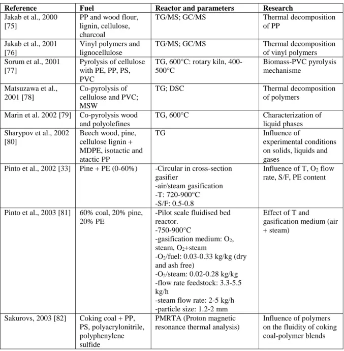
Reference Fuel Reactor and parameters Research
Jakab et al., 2000 [75]
PP and wood flour, lignin, cellulose, charcoal TG/MS; GC/MS Thermal decomposition of PP Jakab et al., 2001 [76]
Vinyl polymers and lignocellulose TG/MS; GC/MS Thermal decomposition of vinyl polymers Sorum et al., 2001 [77] Pyrolysis of cellulose with PE, PP, PS, PVC TG, 600°C: rotary kiln, 400-500°C Biomass-PVC pyrolysis mechanisme Matsuzawa et al., 2001 [78] Co-pyrolysis of cellulose and PVC; MSW TG; DSC Thermal decomposition of polymers Marin et al. 2002 [79] Co-pyrolysis wood
and polyolefines
TG, 600°C Characterization of
liquid phases Sharypov et al., 2002
[80]
Beech wood, pine, cellulose lignin + MDPE, isotactic and atactic PP
TG Influence of
experimental conditions on solids, liquids and gases
Pinto et al., 2002 [33] Pine + PE (0-60%) -Circular in cross-section gasifier -air/steam gasification -T: 720-900°C -S/F: 0.5-0.8 Influence of T, O2 flow rate, S/F, PE content
Pinto et al., 2003 [81] 60% coal, 20% pine, 20% PE
-Pilot scale fluidised bed reactor.
-750-900°C
-gasification medium: O2, steam, O2+steam
-O2/fuel: 0.03-0.33 kg/kg (dry and ash free)
-O2/steam: 0.02-0.28 kg/kg -flow rate feedstock: 3.3-5.5 kg/h
-steam flow rate: 2-5 kg/h -particle size: 1.2-2 mm
Effect of T and
gasification medium (air + steam)
Sakurovs, 2003 [82] Coking coal + PP, PS, polyacrylonitrile, polyphenylene sulfide
PMRTA (Proton magnetic resonance thermal analysis)
Influence of polymers on the fluidity of coking coal-polymer blends
12 Matsuzawa et al., 2004 [83] Cellulose, PE, PP, PS, PVC TG; 200-600°C Synergy Pohorely et al., 2006 [63] 77% brown coal, 23% PET -FB -1)T FB 849-906°C, T freeboard: 896 ; 2)T FB 850-993°C, T freeboard 905°C -gasification medium: 10% O2 in N2 Influence of T of FB and freeboard on minor and major gas components and tar
Aznar et al., 2006 [84]
Coal, biomass and plastics (PP, PE) mixture; 100% plastics
BFB, 750-880°C, ER: 0.30-0.46; air gasification, dolomite catalyst
Influence of T, ER, secondary air, feedstock composition on syngas characteristics Jimenez and Ruseckaite, 2007 [85] Polycaprolactone and cellulose TG/DTG Interaction between PCL andcellulose Sharypov et al., 2007 [86] Brown coal + PE 100%) or + PP (0-100%) -TG -T: 430°C -Fe-catalyst -brown coal: < 0.1 mm; composition (%): ash 4.6; C 62.9; H 5.1; N 0.6; S 0.2; O 26.6 -PE: Mn 20 000 -PP: Mn 10 000 -polymers < 0.5 mm
Synergetic effect with and without catalyst
Pinto et al., 2007 [87] Coal, petcoke, pine, 10-20% PE
-particle size 1.25-2mm dolomite, olivine, Oxides (Zn, Co, Mo), Mg and Ni-dolomite catalysts
Quality of syngas; tars and nitrogen abatement, comparison of catalysts Kuramochi et al.,
2008 [88]
Demolition wood and PVC-film (10/1)
Quartz batch reactor; 600°C Effects on HCl reduction Cai et al., 2008 [89] -Low volatile coal
(LVC) (< 150 m), HDPE, LDPE, PP (<500 m) -LVC-HDPE (5%), LVC-LDPE (5%), LVC-PP (5%)
-TG: 100-750°C (N2 atm) Synergetic effect
Pinto et al., 2009 [90] Low ash and high ash coal, RDF (10-20%), olive bagasse, pine 20%), PE (10-20%)
-first fixed reactor (dolomite), second Ni-catalyst
-T: 850°C
-steam flow rate: 5 kg/h -ER: 0.
Influence on catalysts on gas composition for pure fuels and mixtures
Paradela et al., 2009 [91] Pine + 56% PE, 17% PS, 27%PP Autoclave; T: 350-450°C; t: 5-30 min; P: 0.2-1.0 MPa Influence of operating parameters on product yield and composition. Brebu et al., 2010 [92] Pine, cellulose + PP, PE, PS Pine + PP, PE, PS: 1/1 Pine/PE/PP/PS:3/4/2/ 1 Cell/PE/PP/PS: 3/4/2/1 TG, DTG up to 500°C Synergetic effect of biomass/polymers Mastellone et al., 2010 [93]
Lignite (low and high S), mixed plastics, (30-50%), wood
-BFB
-T reactor: up to 850°C -ER: 0.1-0.4
-feedstock analysis: see table 1 in reference
13
Song et al., 2010 [94] RPF (refuse plastic fuel), low-quality coal
Pyrolysis and gasification: 700-1000°C; catalyst: Ni, NiO, Mg, + Al2O3 and Fe2O3
Effect of catalysts on pyrolysis and
gasification of RPF and RPF and coal mixture Ruoppolo et al., 2010
[95]
Wood and coal (7/3) co-gasification
FB steam gasification; 800°C; catalyst (quartzite, Ni-Al2O3, dolomite
Effect of catalyst on gas composition and tar reduction
Ahmed et al., 2011 [96]
PE and woodchips Lab-scale steam gasification (tube furnace) Behavior of 2 compounds mixture Kaewluan and Pipatmanomai, 2011 [97]
Rubber woodchip and rubber waste
BFB, varying ER, ca. 800°C Influence of rubber waste to rubber woodchip with high moisture content
Taba et al., 2012 [98] Coal and biomass Overview article Influence of T on
different parameters Ruoppolo et al., 2012
[46]
Pine, olive husks, plastic chips
Pilot scale CFB; 800-900°C; steam gasification
Influence of steam supply and catalyst on H2 production Wilk and Hofbauer,
2013 [66]
0-100% virgin polymers, plastics from MSW, plastics from ASR, PE (regrind and virgin), wood pellets
DFB; steam gasification Characteristics of syngas
Oyedun et al., 2013, 2014a, 2014b [99], [100], [101]
Bamboo, sawdust or fruit bunch with HDPE or PS
TG Synergetic effect,
kinetics Costa et al., 2014
[102]
PE and rice husk Batch reactor; T: 350-430 °C; P: 2-5 bar; t: 10-60 min
Parameters; synergy
Pinto et al., 2014 [103]
High ash coal, petcoke, pine, 10-20% PE
-first fixed reactor (dolomite), second Ni-catalyst
-T: 850-900°C
-steam flow rate: 5 kg/h -ER: 0.2
-particle size 1.25-2mm
Quality of syngas; tars and nitrogen abatement
Lee et al., 2014 [104] MSW, rubber, plastic, wood
Steam gasification; 1000°C Gas composition and heating value Önal et al., 2014a
[105]
Almond shell, LDPE: ½; 1/1; 2/1 TG-DTG 500°C Bio-oil production Alvarez et al, 2014.b [106] 5, 10 and 20% PE + wood
2-stage fixed bed; steam gasification; Ni/Al2O3
Synergy wood and PE Brachi et al., 2014
[47]
Biomass + PET or tyre rubber
FB; T: 650-860°C; S/F: 0.48-1.08: steam and enriched air
Production of syngas for methanol production Cepuliogullar and Pütün, 2014 [107] Agricultural waste and PET/PVC mixtures
Fixed bed reactor, 800°C; TG, 500°C
Thermal and kinetic characteristics and caracterization of pyrolysis products Abnisa et al. 2014
[108]
Palm shell and PS Fixed bed reactor; 500°C Production of
high-grade oil Zaccariello and Mastellone, 2015 [109] -Coal/recycled wood/plastic waste (30-100%)
-Plastic from separate collection of post-consumer packaging material
-pre-pilot BFB, 850°C
-gasifying agent: air
Gas composition as a function of fuel composition
14
Kumagai et al., 2015 [110]
Wood sawdust + PP Two-stage tube reactor; 800°C, steam Ni-Mg-Al-Ca catalyst with different Ca content Lopez et al., 2015 [24] Pine + HDPE (50/50; 75/25)
Conical spouted bed reactor, 900°C, S/F=1, olevine as primary catalyst
Products yield (gas, tar, char) and gas
composition as function of HDPE Yang et al., 2015 [111] Rice straw + PVC, PET, PE
TG/DTA; CO2 gasification; Synergetic effect Li et al., 2015 [112] Waste rubber
(0-100%), plastic and cornstalk (10%)
Fixed bed; up to 550°C Influence of rubber and
cornstalk on oil and char yield, oil composition Dorado et al., 2015 [113] Cellulose + PET, PP, HDPE, LDPE, PS Micro pyrolyser, 650°C, HZSM-5 catalyst Influence of plastics on conversion of biomass; distribution of carbon from feedstock on pyrolysis products
Xue et al, 2015 [114] Oak and HDPE FB ; 525-675°C Influence of parameters
and feedstock composition on gas, liquid and char characteristics Zhou et al., 2015
[115]
Biomass (hemicellulose, cellulose, lignin) and PVC
Fixed bed reactor; 800°C Synergistic effects
Robinson et al., 2016 [34]
Wood and PET Air-blown BFB; 725, 800,
875°C;
Comparison for wood and wood-PET pellets: gas composition, heating value, cold gas
efficiency… Kumagai et al., 2016 [116] Beech wood + PE BW/PE: 100:0 -0:100 TG; 650°C Influence of plastics on cellulose pyrolysis Dewangan et al., 2016 [117] Sugarcane bagasse + LDPE SCB/LDPE: 9:1; 3:1; 1:1; 1:3
Semi-batch reactor, 350-550°C Synergetic effect on products yield and characteristics of pyrolysis liquids
Dong, 2016 [118] Wood, cardboard,
food, PE
FB; 650°C; N2, CO2, steam gasification
Gasification with emphasis on energy, environment and LCA Ephraim, 2016a [119] Poplar wood +
HDPE, PS, PVC : 0-5-10-30-100 wt% plastic
Fixed bed reactor; 750 °C Synergistic effects of plastic type and content on product yield, gas specie yield and gas heating value. Yang et al., 2016 [120] Biomass (cedar, sunflower, Japonica stem) –LDPE mixtures
Dropdown tube reactor, 600°C Oil production
Chen et al., 2017 [121]
Paulownia wood + PP, PVC, PET
TG; 50-1000°C Synergetic effects
3.2. Properties and thermogravimetric behavior of plastics and biomass
Most of the researches in thermochemical conversion of plastics have been carried out with thermoplastics polymers, such as PET, PE, PVC, PP, PS or a mixture of these compounds. The plastic structure is a long hydrocarbon chain that could contain aromatic cyclic groups or
15
oxygenated groups. From their chemical formula, these polymers except for PET and PVC, are only composed of carbon and hydrogen. However, they may also contain low contents of oxygen due to the presence of additives, impurities or moisture.
In addition, it has been shown that the volatile matter content is very high (at least 94% except for PET).
It should be noticed that PET, PE (LDPE and HDPE) and PP, first melt and then decompose; for PVC, degradation and melting temperature are very close; for PS the degradation temperature is clearly lower than the melting temperature [122].
Many authors gave TG curves for biomass, wood and different types of plastics [75]–[77], [80], [85], [89], [92], [100], [107], [116], [117], [119], [121]–[124]. Figure 6 gives the TG and DSC curves as a function of temperature of HDPE, PS, PVC and for poplar wood (PW) and a waste wood sample (W3).
Figure 6: TG and DSC curves as a function of temperature of HDPE, PS, PVC and for poplar wood (PW) and a waste wood sample (W3) [119]. 0 10 20 30 40 50 60 70 80 90 100 0 100 200 300 400 500 600 700 800 T G ( w t. % ) Temperature ( C) W3 PW HDPE PS PVC 0 5 10 15 20 25 0 100 200 300 400 500 600 700 800 DT G ( w t.% /min ) Temperature ( C) W3 PW HDPE PS PVC
16
The behaviour can be summarized as follows. Desorption of water starts below 100°C for the wood samples. HDPE melts at around 130°C, which results in a sharp endothermic peak in the DSC curve, a well-defined melting temperature being characteristic of polymers with a high degree of crystallinity. Contrary to HDPE (95% crystalline), PVC and PS are amorphous (<15% crystalline) and melt over a wide temperature range, so that no peak can be observed. Between 200 and 500 °C, all plastic and wood samples lose mass due to devolatilization. The plastics have different thermal stabilities, because of their different polymer chain structures. The dissociation energies of C-H, C-Cl, C-C bonds in polymers are 414, 339 and 347 kJ/mol, respectively [119], which can explain that HDPE has the highest thermal stability and PVC the lowest, as shown by the TG curves. For PVC, the char residue yield corresponds to 3.4%, whereas HDPE and PS are completely decomposed. Other thermogravimetric analyses conducted with virgin plastics in nitrogen showed also a char yield of about 10wt% from PET and less than 3wt% from LDPE, PP and PS [125], these char yields are highly correlated to the degradation mechanism pathways.
In general, biomass has a higher oxygen, a higher moisture and higher ash content, but a lower carbon content than plastics, and contains less volatiles than plastics. Polyolefines (PE, PP) and PS consist only of carbon and hydrogen; PET contains 30 to 40 % of oxygen; PVC contains 56.5% of chlorine. Waste plastics can have different compositions as they usually consist of a mixture of different (contaminated) plastics. The two wood samples in Figure 6 have a similar thermal behaviour with devolatilization in the range of 190 to 400 °C. Wood consists mainly of cellulose, hemicellulose and lignin. On heating, hemicellulose decomposes first (190 to 290°C), followed by cellulose (290 to 360°C) and then lignin, which decomposes over a broad temperature range (360 to 500°C). After devolatilization, charring occurs whereby a char is formed. For the wood samples char residues correspond to 12 to 35%. Thus, wood yields in general more char than plastics.
3.3. Influence of feedstock type on the pyro-gasification products
During thermal conversion, plastics are transformed into gas, bio-oil and char. The industrial development of pyro-gasification processes is held back by the production of unwanted by-products, which decreases efficiency and sometimes requires very costly treatments [126], [127]. For char, a technology for downstream recovery of solid is required, otherwise char accumulation would clog plug-flow reactors. Gaseous phase recovery should limit tar condensation as this leads to fouling and blocking of the process equipment [128]. In addition, gas composition (e.g. H2/CO and contaminants) should be determined in view of the
subsequent application and the post-treatment process.
It appears from the TG curves previously discussed, and from other studies that pure plastics give very little char compared to wood [63], [129]–[133]; the same is true for real waste plastics [35].
Several studies have shown that the type and composition of biomass/plastics feedstock influences the distribution of the pyro-gasification products (gas, tar/oil, char) and their characteristics and composition [84], [90], [93], [134].
Gas composition
Lopez et al. (2015) [24] studied the effect of HDPE (0-100%) co-feeding on the catalytic steam gasification of biomass (spouted bed reactor; 900°C; S/F=1); co-feeding uses two different entries followed by a mixer which is particularly suited for very different densities. The gas yield increased with the HDPE content of the feed and was for pure HDPE more than 2.5 times
17
higher than for biomass; the tar content in the gaseous stream decreased by a factor of 10 going from 58.2 g/Nm3 on a dry basis for biomass to 5.1 g/Nm3 for HDPE; the char yield decreased from 4.3% for biomass to almost negligible (0.3%) for HDPE. The great differences between the product distributions for HDPE and biomass were explained by the complex composition of the lignocellulosic biomass compared to plastics, related to the short residence time in the reactor. The biomass is pyrolysed into gas (H2, CO, CO2, CH4), tar and char. HDPE, made up
of long chains of hydrocarbons, is cracked at high temperature following a random chain scission mechanism and gives a high yield of gas mainly light olefins, a small amount of liquid products (tar), mainly aromatic hydrocarbons, and no char. Both the tar and char yield decreased with increasing HDPE content, and were even lower (positive synergistic effect) than predicted by linear interpolation from the yields for the separate feed. 25% HDPE in the feed reduced tar from 58.2 to 32.0 g/Nm3, 50% HDPE reduced it further to 9.7 g Nm3. Increasing the amount of HDPE in the mixture from 25 to 50%, increased the H2 concentration
from 40% to 57%, but a further increase of HDPE did not give more H2. When the amount of
HDPE increased from 0 to 100%, the CH4 concentration decreased from 20 to 6%, CO
decreased only slightly and CO2 first decreased and then increased slightly.
Pinto et al. (2002) [33] observed in the steam co-gasification of biomass and PE (circular in cross-section gasifier, 835 °C), that with increasing amounts of PE in the feed, H2 increased,
CO and CO2 decreased, methane first decreased and then increased, and hydrocarbons and tar
also decreased. With increasing PE, from a PE content of 20% the gas composition remained almost constant with a maximal hydrogen concentration of about 50%. Ahmed et al. (2011) [96] (steam gasification; 900°C) observed for the gasification of PE/woodchip mixtures peak values for syngas yield, H2 yield, and hydrocarbon yield for PE percentages of about 80% PE.
Alvarez et al. (2014) [106] studied the co-gasification (two-stage fixed bed; pyrolysis 600°C; steam gasification 800°C; with and without Ni-based catalyst) of wood sawdust and 20% PP, HDPE, PS or real plastics. The highest gas yield and lowest tar and char yields were obtained for the polyolefines. With increasing amounts of polyolefines in the biomass/plastic mixtures, H2 and C1-C4 concentrations increased and CO and CO2 decreased. Increasing the amount of
PP in the woodchip/PP mixture from 0 to 20 %, increased the gas yield from 51.6 to 57.0% and the H2 concentration from 30.3 to 36.1%. The H2 concentration significantly increased
further to 52.1%, in the presence of a Ni-based catalyst. The release of H2 is also favoured in
18
Figure 7: Gas composition and hydrogen production for different biomass/PP ratios [106]
Dong (2016) [118] pyro-gasified (FB, 650°C, 15 min) 4 potential components of MSW (poplar wood, cardboard, food waste and PE) under 3 reaction atmospheres (N2, steam, and CO2).
Under all 3 atmospheres and for the pure components the H2 and CH4 concentrations increased
in the order: poplar wood<cardboard<food waste<PE; for CO and CO2 the order was opposite.
Co-gasification of PE with wood, cardboard or food waste, as binary mixtures, increased the concentration of H2 and CH4 and decreased the concentration of CO and CO2 even more than
expected by linear calculation from the individual components, due to a synergistic effect. Wilk and Hofbauer (2013) [66] co-gasified (DFB, steam gasification, 850°C) soft wood pellets and different types of plastics (up to 100%): virgin and recycled PE from packaging, MSW plastics and plastics from treatment of end-of-life vehicles treatment (shredder light fraction, SLF). It appeared that the H2 concentration on average remained almost constant upon addition
of plastics to wood. For mixtures, non-linear effects were observed, but no unique trend in H2
formation as a function of the share of plastics could be givenfor the different plastic materials, or even for different sorts of PE (recycled or virgin). Linear interpolation overestimated the H2
yield from SLF and MSW plastics, but underestimated it for pure and recycled PE. The concentration of CO and CO2 decreased with an increasing share of plastics in the mixture. The
decrease was steeper for PE plastics than for SLF (shredder light fraction originating from end-of-life vehicles) and MSW plastics, which is according to Wilk and Hofbauer (2013) [66] related to the amount of oxygen in the feedstock (wood>MSW>SLF>PE~recycled PE) (Figure 8). With increasing plastic fraction, CH4 and CnHm concentrations as well as tar yield increased.
A significant decrease in char production was only noticed for virgin PE. Zaccariello and Mastellone (2015) [109] reported that, when 20% recycled plastics was mixed with natural wood (BFB, 850°C), the concentrations of H2, CO, CO2 decreased and CH4, CnHm, and tar
increased. These results are partially at variance with the literature discussed so far. No information was however provided on the ‘recycled plastics’ or on the ‘natural wood’ used.
19
Figure 8: CO2 in dry gas product (SLF= shredder light fraction originating from end-of-life vehicles; PE regrind=derived
from packaging waste foil; PE=virgin PE) [66].
According to Robinson et al. (2016) [34], pyro-gasification (FB with bed material olivine, 725 to 875°C, air) of wood–PET pellets has a worse performance than wood pellets alone: tar concentrations were much higher and heating values were lower; moreover the H2
concentration in the gas was lower, whereas concentrations of CO2 and CO were somewhat
higher than for wood pellets. Robinson et al. (2016) [34] do not provide an explanation for these observations, but these results could indicate that PET should better be avoided in co-gasification of plastics and biomass. This should not really be a problem as methods for PET recycling exist. The high tar concentrations in the syngas tents reported by Robinson et al. (2016), were also observed by Brachi et al, 2014 [47] (FB, steam + oxygen + nitrogen, 745-856°C).
Alvarez et al., (2014) [106] added 20% PS to biomass and noticed, compared to pure biomass, an increase of the gas yield and of the oil yield, and a decrease of the char yield. They compared the behavior of polyolefin and PS when added to biomass: PS addition resulted in a lower gas yield, higher oil yield, and slightly higher char yield. H2, CO and CO2 concentrations in the gas
were higher, those of CH4 and CnHm lower. It should be noticed that Wu and Williams., (2010)
[17] came to similar conclusions, when comparing pure polyolefines with PS. Ephraima, (2016) [119] (FB, semi continu, N2 atmosphere, 750°C) noticed with increasing PS addition to
biomass, a slight increase in H2 concentration up to 30% PS and then a decrease; concentrations
of CH4, CnHm, CO and CO2 decreased over the whole plastic content range (0-100%). Since
PS contains an aromatic cycle, Alvarez et al. (2014) [106] concluded that cracking requires higher temperatures (they used 600°C for pyrolysis and 800°C for steam gasification, with or without catalyst).
Ephraima, (2016) [119]also studied the pyrogasification of biomass with PVC. With increasing amount of PVC in the mixture, gas yield (mainly HCl) and H2 concentration increased
significantly, CH4 and CnHm concentration remained nearly constant, tar yield decreased and
char yield first increased up to about 30% of PVC and subsequently decreased with higher PVC concentration.
20
Kaewluan and Pipatmanomai (2011) [97], gasified (BFB, air, ER 0.3 to 0.5, 800°C) high moisture (9.5 to 27%) rubberwood chips with rubber waste in a bubbling fluidized bed reactor. Addition of 20% waste rubber to 27% moist rubberwood chips, increased the bed temperature from 700°C to 770°C, and showed several advantages compared to the gasification of air-dried biomass, such as increased H2 production due to the presence of water and a higher heating
value of the syngas.
Lee et al. (2014) [104] investigated the production of clean gaseous fuels (syngas) produced from the gasification of MSW, rubber, plastic and wood (fixed bed, 700°C, using 1000°C steam). A high-temperature gasification process with steam at 1000°C was applied, to generate syngas whose concentration is, mainly because of the water gas shift reaction, dominated by H2 and can be used as gaseous fuel. There were only minor differences between the results
obtained for the different feedstocks, proving that steam gasification can convert any material containing C, H and O, into a gaseous fuel with 50-60 % H2, about 10 % CO and CO2 and
about 3% CH4, despite different characteristics of the feedstocks (C between 43 and 81%; O
between 3 and 40%; moisture between 0 and 15%; LHV between 14 and 32%). Among the four feedstocks studied, plastics gave the highest H2 concentration and the lowest
concentrations of CO, CO2 and CH4 concentration, wood feedstock gave the lowest H2
concentration and the highest CO concentration. The highest LHV value was obtained for rubber (10.8 MJ/m3, the lowest for plastics (7.8 MJ/m3).
Also the type of biomass has an important influence on the decomposition of polymers and was studied by different authors [92], [107], [119], [120], [135]–[139]. Cepeliogullar and Pütün, (2014)[107], [138], studied the co-pyrolysis (semi-continuous reactor) of PET and PVC, each mixed with 4 different types of biomass. They observed for the PET mixtures, that the oil yield increased with the lignin content of the biomass, or with the amount of char produced. For the PVC-biomass mixtures gas yield increased with increasing lignin content of the biomass. Zhou et al. (2015) [115], co-pyrolysized PVC with xylan, cellulose or lignin (1/1 mixtures). They measured for xylan and lignin an increase in gas yield and a decrease in char yield, whereas cellulose gave the opposite results. The decrease in HCl yield was much higher for lignin than for the other biomass compounds. Yang et al. (2016) [120] investigated the occurrence of aliphatic and aromatic hydrocarbons in the oil obtained by fast co-pyrolysis of LDPE and different types of biomass. They observed a positive synergistic effect for the aliphatic hydrocarbons; the synergistic effect for the aromatic hydrocarbons was positive or negative, depending of the type or biomass in the feedstock.
Tar and char
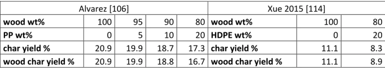
As mentioned previously, pure plastics provide small amount of tar, due to their high amount of volatile matter. As a result the amount of char obtained from pyro-gasification of biomass and plastic mixture is often decreased by the presence of plastics. The char yield is basically calculated over the total mass of the feedstock. However, this is interesting to define a biomass char yield which should be calculated from the mass of the residue over the initial mass of biomass. Table 4 shows the values of experimental char yield found in the literature, as well as the calculated wood char yield. For these examples, the values of this parameter are not so far from the char yield obtained experimentally, meaning that the decrease of char yield is mainly related to a “dilution phenomenon”.
21
Table 4: Comparison of char yield (experimental) and wood char yield (calculated)
Alvarez [106] Xue 2015 [114]
wood wt% 100 95 90 80 wood wt% 100 80
PP wt% 0 5 10 20 HDPE wt% 0 20
char yield % 20.9 19.9 18.7 17.3 char yield % 11.1 8.3
wood char yield % 20.9 19.9 18.8 16.7 wood char yield % 11.1 8.9
Finally, the composition of tar in pyro-gasification is also significantly modified by co-feeding plastics with biomass, compared to the individual components. The addition of plastics to biomass reduces the concentration of phenols and furans in the tar fraction; phenols and furans contain oxygen and are typically associated with tars from wood gasification [24], [34], [46], [66], [80], [91], [105], [108], [114]. Lopez et al., (2015) [24] obtained for the gasification of a biomass-HDPE mixture (1/1) a tar composed of 80% of aromatic and polyaromatic hydrocarbons, mainly naphthalene and toluene, and of only 20% of phenols. Ruoppolo et al. (2010) [95], measured a significant decrease in phenol and a significant increase in phenanthrene for an increasing amount of plastic in a biomass-PE mixture.
Robinson et al. (2016) [34] in their study of the gasification of commercial hardwood and plastic PET waste (BFB; 725-875°C) divided tar components into 5 groups: light non-oxygenated tar compounds (benzene, toluene, xylenes, etc.), phenolic compounds, naphthalene and similar compounds, PAHs (from fluorene to coronene) and gravimetric tar (compounds too heavy for gas chromatography). Gases produced from wood pellets contained mainly phenolic compounds. Gases produced from wood–PET pellets contained ca. 10 times greater concentrations of light non-oxygenated compounds than gases produced from wood pellets. Abnisa et al. (2014) [108] measured a pH of 2.5-2.7 for tar obtained by the pyrolysis of mixtures of palm shell and PS and attributed it to the presence of low molecular weight carboxylic acids. Cepeliogullar and Pütün (2014) [138] investigated the co-pyrolysis of agricultural waste with PET and with PVC, and measured significant amounts of benzoic acid and of PAHs in the tar of respectively a 1/1 biomass-PET mixture, and a 1/1 biomass-PVC mixture.
The pyrolysis of PVC with other feedstocks such as biomass waste, coal or other plastics has been recently reviewed by Yu et al. (2015) [140]. Blends containing low PVC content (e.g. 2 wt%) would cause significant difference amount of chloro-organic compounds in pyrolysis oil. For example, Uddin et al., (1999) [141] studied the pyrolysis of different blends of PVC with PE, PP and PS. Around 3-12 % of chlorine were found in liquid oil fraction. The formation of chloro-organic compounds was assumed as the result from the combination of HCl, formed from PVC degradation, and organic compounds, formed from other feedstocks [140]. Yuan et al. (2014) [142]studied the thermal degradation of pure PVC granules or PVC pipe scraps. The dechlorination efficiency could be complete above 320°C. The formation of chloro-organic compounds could be limited by using metals oxides as adsorbents during PVC pyrolysis. Among different metal oxides investigated, Masuda et al. (2006) [143]showed that La2O3 and
ZnO were the most efficient to inhibit the formation of chlorobenzene. On the other hand, for the dechlorination of pyrolysis oil, catalytic processes are preferred, as previously reviewed by Yu et al. (2015) [140]. Metal oxides supported on different supports are usually used [140]. Aznar et al. (2006) [84], Pinto et al. (2009) [90]; Mastellone et al. (2010) [93] and Zaccariello and Mastellone (2012) [134] concluded from their experiments that different types of fuels (biomass, plastics, coal) may be substituted by each other, without requiring important changes to the gasifier. They highlighted that each component may change the product distribution and the concentration of the components in the gas. In general, but some papers came to other
22
conclusions, wood promotes the formation of a solid char composed of almost pure carbon and reduces the presence of heavy hydrocarbons in the syngas, thus leading to a cleaner syngas, with less heavy hydrocarbons and tar, but with a lower calorific value.The presence of plastics on the other hand, in general increases the yield of H2, light hydrocarbon and gas, affording a
higher heating value syngas [24], [33], [66], [96], [106], [134]. Conclusions
It is clear that the information given, even for 1 plastic (PE or PP) mixed with biomass is not always completely consistent. Product distributions for biomass and plastics and their mixtures, as well as concentrations of the gases, depend in addition to the plastic and biomass composition on various other parameters (reaction time, gasifying agent, temperature, heating rate, catalysts, etc., these factors will be discussed later), so that it is not surprising that sometimes conflicting results are reported in literature [144]. However for polyolefines (PE and PP) and PS/biomass mixtures an almost general consensus exists: with increasing PE or PP, gas yield increases, tar and char decrease, H2 increases, CH4, hydrocarbons, CO and CO2
decrease. For PET/biomass mixtures much less information is available but the data of Robinson et al. (2016) [34] for air gasification indicate almost opposite trends than for PE or PP. For real plastic waste, little information is available and it is usually contradictory [17], [19], [104], [106]. It would be interesting to investigate the ‘real plastics fractions’ obtained during separate collection of a mixture of some plastics (e.g. by Fost Plus in Belgium), and also the resulting fractions obtained during separation of these plastics.
3.4. Synergistic effect during the thermoconversion of plastics and other feedstocks (biomass, coal)
As mentioned before, synergistic effects occur during the thermoconversion of plastic/biomass, plastic/biomass/coal and plastic/coal mixtures. This means that the experimental values, for example the gas, oil or char yield, or the gas composition, differ from those calculated by linear interpolation on the basis of the results for the pure components in the feedstock. The mechanisms of these synergistic effects were studied by different authors [75]–[77], [79], [80], [86], [89], [92], [96], [100], [102], [107], [115]–[117], [121], [122], [138], [145] .
Plastics (PS, PE, PP, PET, PVC) devolatilise in a higher temperature range (300-500°C) than biomass (200-400°C) (see 3.2.), making interactions and synergy possible between plastics and the volatiles thereof, with char from biomass. The char plays the role of radical donor in the initiation of the polymer chain scission (H-transfer from plastic to coal/biomass) and may also adsorb volatiles from polymers. Dong (2016) [118] observed a higher synergy between food waste and PE than between poplar wood or cardboard and PE, and attributed this to food waste char being more porous and thus having more catalytic effect on gas-solid phase reactions.
Catalytic properties of char from thermo-conversion of biomass were intensively studied for a large family of chemical processes [81], [146]–[148].
Compared to other plastics, polyolefins decompose more easily in the presence of cellulosic materials. During the pyrolysis of biomass-polyolefin mixtures, the onset temperature of the polymer decomposition is lowered as was demonstrated for PP in the presence of beech wood [75], [79]. Also, the co-pyrolysis of almond shell with HDPE was found beneficial for oil production and thus for the decomposition of HDPE [105]. Yang et al. (2016) [120] studied the fast co-pyrolysis of woody biomass with up to 50 wt.% of LDPE: at 600°C and under inert atmosphere, the oil yield was highest for the 1/1 LDPE/ biomass mixture, higher than for wood or LDPE alone. Dorado et al. (2015) [113] added different polymers (PE, PP, PS, PET) to biomass, in view of reducing coke formation to increase catalyst (HZSM-5) lifetime. It appeared that PE and PP were most efficient in the conversion of cellulosic materials: during
23
pyrolysis these polyolefines decompose into olefins that react with the oxygenated primary pyrolysis products from biomass, avoiding coke formation. PET and PS produced lower olefin concentrations.
Biomass/PS mixtures and biomass/PET mixtures, behave in a different way than biomass/polyolefines mixtures during thermal conversion [92], [100], [121], [138]. For PET, a variety of oxygen-containing products and aromatic hydrocarbons are released upon degradation. These may react with the primary char from wood, thus maximize the char [121].
.
Oyedun et al. (2013), (2014b) [99], [101] used two modelling approaches to study the synergetic effect of the co-pyrolysis of bamboo/PS blends. A significant interaction between bamboo and PS was shown from the mass loss, volatile evolving rate and the overall energy used. The energy of the mixed-blends was lower than this calculated from the pyrolysis of the separate components of the blends, bamboo and PS. Oyedun et al. (2014a) [100], also observed
a much larger deviation between experimental and predicted TGA’s under N2 atmosphere for
PS/biomass than for HDPE/biomass blends and attributed this to the decomposition temperature of the lignin fraction of biomass (400°C) overlapping better with the PS decomposition temperature interval (400-425°C) than with the one of HDPE (455-510°C). According to Jakab et al. (2001) [76] the decomposition of PS is correlated with the amount of char produced from the added biomass. The amount of char increases in the order cellulose<beech wood<lignin<charcoal and has an increasing impact on the decomposition of PS.
The thermal degradation of PVC is more complex than for other polymers: whereas most polymers decompose in one stage, PVC decomposes in two stages. Dechlorination starts lower than 200°C at the surface, resulting in cyclization/aromatization, and becomes significant at 300°C, while aromatic hydrocarbon release starts at 350°C and become significant above 450°C [149]. The first stage of PVC degradation almost perfectly matches the temperature interval of biomass and lowers the degradation temperature of biomass, enhancing the release of volatiles and increasing the char yield [77], [83], [107], [121], [122], [138]. Ephraim (2016a) [119] observed a significant positive synergy for a wood /PVC mixture (7/3) on char and tar yield: the char and oil yield increased by 44 and 30% respectively, relative to the yield predicted by linear interpolation from the yields for the pure components. A corresponding, but negative synergy in gas (HCl) was observed [119].Also Kuramochi et al. (2008) [88] and Zhou et al. (2015) [115] observed a decrease in HCl when co-pyrolysing biomass and PVC. The chlorine of PVC was preferentially found in the ‘oil fraction’. According to Ephraim(2016a) [119], it is mainly present as HCl gas dissolved in the oily phase after condensation, in contradiction with Kuramochi et al. (2008) [88] and Zhou et al. (2015) [115], who suggest that some chlorine of the PVC might be present in organic chlorinated compounds.
4. Operational parameters
Of course selecting the feedstock mixture for pyro-gasification is just a start, and it may also be dictated by practical considerations (availability, cost, etc.). The final product yields and product distribution, as well as the gas composition depend also on several operational parameters. These will now be discussed.
24
4.1.Gasifying agent
The gasifying agent is a key factor in determining the quality of the syngas and its subsequent use. Common gasifying agents are air, oxygen, steam, carbon dioxide and mixtures thereof. Steam gasification is endothermic, so heat must be supplied to the process. If some oxygen is present in the gasifying medium, it can give the heat needed for gasification, so that oxygen/steam mixtures are often used. CO2, or a mixture of steam and CO2, can also be used
as gasifying medium.
In their study of the co-gasification of coal, biomass and plastics wastes with air/steam mixtures in a fluidized bed reactor, Pinto et al., 2003 [81] studied the influence of the gasification medium: different combinations of air and steam were investigated. It was shown that increasing the oxygen (in air) concentration reduced hydrocarbons and tar due to partial combustion reactions, but the gas produced was diluted due to nitrogen coming in with air, thus reducing the heating value. Steam and air gasification gave similar gas yields; steam gasification favoured steam reforming reactions, whilst air gasification favoured combustion reactions. Therefore, H2 and hydrocarbon concentrations were higher with steam gasification
than with air gasification, whereas CO and CO2 were lower, as replacing air by steam reduced
combustion of char and volatiles. Similarly, higher fractions of oxygen (oxygen/(oxygen +steam)) decreased the content of H2, methane and other hydrocarbons, and increased CO and
CO2 concentrations.
As discussed by Aznar et al. (2006) [84], air is the most common gasifying agent for reasons of cost. With air a product gas with low heating value (<6MJ/m3), and containing 7 to 12 % of hydrogen is obtained. To produce gas with a high heating value (10-20 MJ/Nm3), pure oxygen
may be used, and thus avoiding dilution by nitrogen, although the cost is higher. Pure steam is also a popular gasifying agent: it gives syngas with a high hydrogen content (50-55%), but also with a high tar content, and is very endothermic. Mixtures of steam and oxygen require less external heat, and give a medium heating value (12 to 14 MJ/ m3) syngas.
Lee et al. (2014) [104] investigated the production of clean gaseous fuels (syngas) produced from the gasification of MSW, rubber, plastic and wood. The results of steam gasification (700°C, using 1000°C steam) were compared to air-blown (900°C) gasification. The main difference was the H2/CO ratio: in steam gasification the H2/CO ratio was 12, compared to only
1 in air-blown gasification. The LHV of the syngas from steam gasification was more than twice that obtained with air-blown gasification. The differences between both gasifying agents were due to extra water gas shift reaction in steam gasification and N2 dilution in air-blown
gasification
Dong (2016) [118] studied pyro-gasification (650°C, 15 min) of 4 components of MSW (poplar wood, cardboard, food waste and PE) under 3 reaction atmospheres (N2, steam, and CO2). Both
steam and CO2 (dry gasification) are effective in enhancing syngas yield and change syngas
properties compared to N2. In the case of poplar wood the syngas yield rises from 0.070 m3/kg
(N2) to 0.088 (steam) and 0.074 (CO2), respectively, for the other wastes a similar increase was
noticed. The higher syngas yield with CO2 and H2O than with N2 is attributed to the occurrence
![Table 1: Main syngas contaminants with their emissions in waste gasification and the target levels of the major applications [36], [40]-[42]](https://thumb-eu.123doks.com/thumbv2/123doknet/12511169.341132/5.892.113.787.875.1135/table-syngas-contaminants-emissions-gasification-target-levels-applications.webp)
![Figure 1: Fixed bed reactors [71] Figure 2: Fluidised bed reactors [71]](https://thumb-eu.123doks.com/thumbv2/123doknet/12511169.341132/11.1263.123.557.107.392/figure-fixed-bed-reactors-figure-fluidised-bed-reactors.webp)
![Figure 6: TG and DSC curves as a function of temperature of HDPE, PS, PVC and for poplar wood (PW) and a waste wood sample (W3) [119]](https://thumb-eu.123doks.com/thumbv2/123doknet/12511169.341132/16.892.109.737.405.1091/figure-curves-function-temperature-hdpe-poplar-waste-sample.webp)
![Figure 7: Gas composition and hydrogen production for different biomass/PP ratios [106]](https://thumb-eu.123doks.com/thumbv2/123doknet/12511169.341132/19.892.183.721.120.528/figure-gas-composition-hydrogen-production-different-biomass-ratios.webp)
![Figure 8: CO 2 in dry gas product (SLF= shredder light fraction originating from end-of-life vehicles; PE regrind=derived from packaging waste foil; PE=virgin PE) [66]](https://thumb-eu.123doks.com/thumbv2/123doknet/12511169.341132/20.892.123.529.136.466/figure-product-shredder-fraction-originating-vehicles-regrind-packaging.webp)
![Figure 9: Syngas composition for poplar wood and PE under N 2 , steam and CO 2 [118]](https://thumb-eu.123doks.com/thumbv2/123doknet/12511169.341132/26.892.107.786.103.998/figure-syngas-composition-poplar-wood-pe-n-steam.webp)
![Figure 9 gives the syngas composition for poplar wood and PE under N 2 , steam, and CO 2 [118]](https://thumb-eu.123doks.com/thumbv2/123doknet/12511169.341132/27.892.108.788.572.684/figure-gives-syngas-composition-poplar-wood-pe-steam.webp)
![Figure 10: Effect on bed temperature on gas composition for co-gasification of pine with 40% of PE and a steam ratio of 0.8 (w/w) [33]](https://thumb-eu.123doks.com/thumbv2/123doknet/12511169.341132/28.892.121.673.360.795/figure-effect-temperature-composition-gasification-pine-steam-ratio.webp)
