SHERBROOKE
Faculty de g^nie Dgpartement de g6nie civil
STRENGTH AND DRIFT CAPACITY OF GFRP-
REINFORCED CONCRETE SHEAR WALLS
Resistance des murs de cisaillement renforces de PRFV
Nayera Ahmed Abdel-Raheem Mohamed
A dissertation submitted in partial fulfillment of the requirements for the degree of
Doctor of Philosophy (Civil Engineering)
Jury: Prof. Brahim BENMOKRANE (directeur de recherche) Prof. Kenneth W. NEALE (codirecteur de recherche) Prof. Murat SAATCIOGLU
Prof. Omar CHAALLAL Prof. Nathalie ROY
These de doctorat Sp^cialiUi: genie civil
1+1
Published Heritage Branch Direction du Patrimoine de I'edition 395 Wellington Street Ottawa ON K 1A0N 4 Canada 395, rue Wellington Ottawa ON K1A 0N4 CanadaYour file Votre reference ISBN: 978-0-499-00396-6 Our file Notre reference ISBN: 978-0-499-00396-6
NOTICE:
The author has granted a non
exclusive license allowing Library and Archives Canada to reproduce, publish, archive, preserve, conserve, communicate to the public by
telecomm unication or on the Internet, loan, distrbute and sell theses
worldwide, for commercial or non commercial purposes, in microform, paper, electronic and/or any other formats.
AVIS:
L'auteur a accorde une licence non exclusive permettant a la Bibliotheque et Archives Canada de reproduire, publier, archiver, sauvegarder, conserver, transmettre au public par telecomm unication ou par I'lnternet, preter, distribuer et vendre des theses partout dans le monde, a des fins com merciales ou autres, sur support microforme, papier, electronique et/ou autres formats.
The author retains copyright ownership and moral rights in this thesis. Neither the thesis nor substantial extracts from it may be printed or otherwise reproduced without the author's permission.
L'auteur conserve la propriete du droit d'auteur et des droits moraux qui protege cette these. Ni la these ni des extraits substantiels de celle-ci ne doivent etre imprimes ou autrement
reproduits sans son autorisation.
In compliance with the Canadian Privacy A ct some supporting forms may have been removed from this thesis.
W hile these forms may be included in the document page count, their removal does not represent any loss of content from the thesis.
Conform em ent a la loi canadienne sur la protection de la vie privee, quelques
form ulaires secondaires ont ete enleves de cette these.
Bien que ces form ulaires aient inclus dans la pagination, il n'y aura aucun contenu manquant.
Last sentence o f article: “The use o f the Electronic Computer in Structural A n a ly sis,” b y Bath K. J., published in Impact, Journal o f U niversity o f Cape T ow n Engineering Society, 1967.
W ith the rise in constructing using FRP reinforcement, owing to corrosion problems in steel- reinforced structures, there is a need for a system to resist lateral loads induced from wind and earthquake loads. The present study addressed the applicability o f reinforced-concrete shear walls totally reinforced with glass-fiber-reinforced polymer (GFRP) bars to attain reasonable strength and drift requirements as specified in different codes. Four large-scale shear walls - one reinforced with steel bars (as reference specimen) and three totally reinforced with GFRP bars - were constructed and tested to failure under quasi-static reversed cyclic lateral loading. The GFRP-reinforced walls had different aspect ratios covering the range o f medium-rise walls. The reported test results clearly showed that properly designed and detailed GFRP- reinforced walls could reach their flexural capacities with no strength degradation, and that shear, sliding shear, and anchorage failures were not major problems and could be effectively controlled. The results also showed recoverable and self-centering behavior up to allowable drift limits before moderate damage occurred and achieved a maximum drift meeting the limitation of most building codes. Acceptable levels o f energy dissipation accompanied by relatively small residual forces, compared to the steel-reinforced shear wall, were observed. Finite element simulation was conducted and the analyses captured the main features of behavior. Interaction o f flexural and shear deformations of the tested shear walls was investigated. It was found that relying on the diagonal transducers tended to overestimate shear distortions by 30% to 50%. Correcting the results based on the use o f vertical transducers was assessed and found to produce consistent results. Decoupling the flexural and shear deformations was discussed. Using GFRP bars as elastic material gave uniform distribution of shear strains along the shear region, resulting in shear deformation ranging from 15 to 20% o f total deformation. The yielding o f the steel bars intensified the shear strains at the yielding location, causing significant degradation in shear deformation ranging from 2 to 40% of total deformation. The results obtained demonstrated significantly high utilization levels of such shear wall type, therefore, primary guidelines for seismic design o f GFRP- reinforced shear wall in moderate earthquakes regions was presented, as no design guidelines for lateral load resistance for GFRP-reinforced walls are available in codes. The ultimate limit
state was addressed by providing strength capacity that limit ductility demand to their safe flexural displacement capacity. The strength demands were derived from ground motion spectra using modification factors that depend on both the strength and energy absorption of the structure. Deformation capacity was derived by proposing new definitions for elastic (virtual yield) displacement and maximum allowable displacement. Strength modification factor was proposed based on the test results. The occurrence of “ virtual plastic hinge" for GFRP-reinforced shear walls was described providing new definitions convenient with the behavior o f the GFRP-reinforced shear walls. “ Virtual plastic hinge” length was estimated based on observations and calculations. Subsequently, the experimental results were used to justify the proposed design procedure. The promising results could provide impetus for constructing shear walls reinforced with GFRP bars and constitute a step toward using GFRP reinforcement in such lateral-resisting systems.
Keywords: Concrete, GFRP bars, cyclic loads, hysteretic behavior, shear walls, deformation, energy dissipation, finite element, design, drift capacity, ductility index.
L ’utilisation grandissante des polymferes renforcds de fibres (PRF) dans le domaine de la construction et les problemes de corrosion des structures renforcees de barres d ’armature en acier demontre l ’utilite d ’un systeme de resistance des charges laterales induites par les charges du vent et les charges sismiques. Cette etude traite de 1 ’applicability de murs de cisaillement en beton arme de barres en polymdre renforcds de fibres de verre (PRFV) pour atteindre une resistance raisonnable et les exigences telles que specifies par les diffdrents codes. Quatre murs de cisaillement ei grande dchelle - dont un mur renforcd par des barres d’acier (dchantillon de reference) et trois murs totalement renforces de barres en PRFV - ont ete fabriques et testes jusqu’ci la rupture sous un chargement lateral cyclique. Les murs renforces de barres en PRFV avaient differents eiancements couvrant les gammes de murs k hauteur moyenne. Les resultats d’essais ont clairement montre que les murs renforces de PRFV peuvent atteindre leurs resistances en flexion sans aucune degradation. De plus, le cisaillement, le glissement et les ruptures d ’ancrage n ’ont pas ete des problemes majeurs et ont pu etre efficacement controles. Les resultats ont egalement montre un comportement recouvrable et auto-centrant ju sq u ’aux limites admissibles avant qu ’un endommagement modere survienne et acheve une deviation maximale, repondant aux limites de la plupart des codes du batiment. Des niveaux acceptables de dissipation d ’energie, accompagnes de forces residuelles relativement faibles, en comparaison avec le mur de cisaillement arme d ’acier, ont ete observes. Une simulation par elements finis est mende et les analyses ont retenu les principales caracteristiques du comportement. L ’interaction des deformations due k la flexion et au cisaillement des murs de cisaillement testes a ete etudide. II a dte trouvd que l ’appui sur les transducteurs diagonaux avait tendance a surestimer les distorsions de cisaillement de 30% a 50%. La correction des rdsultats basde sur 1’utilisation de transducteurs verticaux a dte dvalude et trouvde pour produire des rdsultats consistants. Le ddcouplage des deformations du a la flexion et au cisaillement est discute. L ’utilisation des barres en PRFV comme matdriau dlastique a donnd une distribution uniforme des deformations de cisaillement tout le long de la region de cisaillement, resultant en une deformation de cisaillement comprise entre 15% et 20% de la deformation totale. La limite d ’dlasticite des barres d ’armatures d ’acier a intensifie les deformations de cisaillement, causant une degradation significative dans la deformation de cisaillement comprise entre 2%
et 40% de la deformation totale. Les resultats obtenus ont demontre des niveaux d ’utilisation signiflcativement eleves de tel type de murs de cisaillement. Par consequent, un guide pour la conception sismique des murs de cisaillement renforces de PRFV dans des regions de sismicite moderee a ete presente, tant qu'il n ’y a pas de guides disponibles dans les codes sur la resistance a des charges laterales des murs renforces de PRFV. L ’etat limite ultime a ete adresse en presentant une capacite de resistance qui limite la demande en ductilite a leur capacite de deplacement flexionnel securitaire. Les demandes en resistance ont ete derivees des spectres de mouvement de sols, en utilisant des facteurs de modification qui dependent a la fois de la resistance et de l ’absorption d ’energie de la structure. La capacite de deformation derivee par la proposition de nouvelles definitions du deplacement elastique (plasticite virtuelle) et le deplacement maximum disponible. Un facteur de modification de resistance est propose, en se basant sur les resultats des essais. L ’apparition d ’une "rotule plastique virtuelle" pour les murs de cisaillement renforces de PRFV a ete decrite, tout en fournissant de nouvelles definitions convenables au comportement des murs de cisaillement renforces de PRFV. La longueur de la "rotule plastique virtuelle" est estimee en se referant aux observations et aux calculs. Subsequemment, les resultats experimentaux ont ete utilises pour justifier la procedure de conception proposee. Les resultats prometteurs ont pu fournir un elan pour la construction des murs de cisaillement renforces de barres en PRFV et ont constitue une etape vers 1’utilisation de renforcements en PRFV dans de tels systemes de resistance laterale.
Mots cles: beton, barres en PRFV, charges cycliques, comportement hysteresis, murs de cisaillement, deformation, energie de dissipation, elements finis, conception, capacite de derivation, indice de ductilite.
Thanks to Almighty ALLAH for the gracious kindness in all the endeavors I have taken up in my life.
First of all, the author would like to thank her supervisor, Prof. Brahim BENMOKRANE, for giving an opportunity to conduct such research and providing her with the necessary support at times when it was most needed. The author greatly appreciates to have been advised by Prof. Kenneth W. NEALE who is the co-director of this thesis.
The author would like to express her sincere appreciation to Dr. Ahmed S. FARGHALY, his invaluable and continued support fulfilling my PhD learning process and was instrumental in the completion of this work. Sincere words o f thanks must also go to Prof. Murat SAATCIOGLU and Prof. Omar CHALLAAL for their valuable suggestions and critical comments that helped in advancing the research.
Gratitude must be extended to Prof. Frederic LEGERON for his hospitality to conduct a large scale test at his facility. Sincere words of thanks must also go to our group technical staff; Mr. Martin Bernard, Mr. Simon Kelley, and Mr. Frangois Ntacorigira. I value the assistance of my college Khaled Mohamed for his invaluable help during the experimental program. Thanks are due to all my colleges in our group for their assistance.
I am grateful for the scholarship granted to me by the Canada Research Chair in Advanced Composite Materials for Civil Structures and Natural Sciences and Engineering Research Council o f Canada (NSERC-Industry Research Chair program).
The author is indebted to her parents and parents-in-law, who teach me how to give and not expect return, that is what lies at the heart o f love.
Last but never the least, I wish to extend my deepest love and appreciation to my close family; M y husband Ahmed for his kindness and devotion, and for his endless support which was such an opportunity to sculpture my career to highest level of proficiency; his selflessness will always be remembered. M y daughter Malak and my son Abdel-Rahman for their continuous patience, understanding, sacrifice, and prayers throughout this research. Their help during constructing and testing include many hours of waiting during evenings and nights in a safe area far from mum and dad is greatly appreciated. Thank you my kids.
Nayera Ahmed Abdel-Raheem Mohamed April 2013
ABSTRACT i
RfiSUMfi iii
ACKNOWLEDGEMENT v
TABLE OF CONTENTS vii
LIST OF TABLES xi
LIST OF FIGURES xiii
CHAPTER 1: INTRODUCTION 1
1.1. General Background 1
1.2. Objectives and Scopes 2
1.3. Methodology 3
1.4. Thesis Outlines 4
CHAPTER 2: LITERATURE REVIEW 7
2.1. Reinforcing with FRP Bars 7
2.2. Types of FRP Bars 7 2.3. Properties of FRP Bars 9 2.3.1. General 9 2.3.2. Tensile Strength 9 2.3.3. Compressive Strength 11 2.3.4. Flexure Properties 12 2.3.5. Shear Properties 13 2.3.6. Fatigue Properties 14 2.3.7. Deformability 15 2.3.8. Damping 18
2.4. Steel-Reinforced Shear Walls 19
2.5. Parameters Affecting Shear Walls Strength 20
2.5.1. Wall Aspect Ratio 20
2.5.2. Boundary Element 21
2.5.3. Construction Joint 21
2.5.4. Horizontal and Vertical Reinforcement 22
2.5.5. Foundation of Shear Walls 22
2.6. Behavior of Shear Wall 23
2.6.1. Flexure Behavior 23 2.6.2. Shear Behavior 25 2.6.3. Ductility 26 2.6.4. Stability 28 2.6.5. Confinement 29 2.7. Failure Modes 30 2.7.1. Flexure Failure 31
2.7.2. Diagonal tension or Compression Failure 32
2.7.3. Sliding Shear Failure 33
2.7.4. Anchorage Slip Failure 34
CHAPTER 3: EXPERIMENTAL PROGRAM 35
3.1 Introduction 35
3.2 Details of Wall Specimens 35
3.3 Material Properties 39
3.3.1 Concrete 39
3.3.2 Reinforcement 39
3.4 Design of Wall Specimens 43
3.4.1 Flexure Strength 43
3.4.2 Shear Strength 44
3.4.3 Sliding Shear Strength 46
3.4.4 Anchorage Length 47
3.5 Casting of Test Specimens 48
3.6 Test Setup 50
3.7 Loading Procedure 53
3.8 Instrumentation 53
CHAPTER 4: EXPERIMENTAL RESULTS AND ANALYSIS 57
4.1 Introduction 59
4.2 Experimental Observations 60
4.2.1 Steel-Reinforced Wall 62
4.2.2 GFRP-Reinforced Walls 63
4.3 Effect of Test Parameters on Wall Response 66
4.3.1 Comparison of ST 15 and G15 66
4.3.2 Comparison of Different Aspect Ratios 68
4.4 Energy Dissipation 69
4.5 Secant Stiffness 72
4.6 Prediction of Ultimate Load Capacity 74
4.6.1 Plane Sectional Analysis 74
4.6.2 Finite Element Analysis 76
4.7 Conclusion 84
CHAPTER 5: FLEXURE AND SHEAR DEFORMATIONS 87
5.1 Introduction 89
5.2 Shear Distortion 89
5.3 Deformation Analysis 92
5.3.1 Decoupling Flexure and Shear Deformations 93
5.3.2 Center of Rotation 95
5.3.3 Original and Corrected Lateral Displacement 100
5.3.4 Decoupled Flexure and Shear Deformations 101
CHAPTER 6: DRIFT CAPACITY BASED DESIGN 105
6.1 Introduction 107
6.2 Design Principles for Steel-Reinforced Shear Walls 108
6.2.1 Simplified Expressions 111
6.3 Proposed Provisions for GFRP-Reinforced Shear Walls 112
6.4 Drift Capacity of GFRP-Reinforced Shear Walls 115
6.4.1 Idealized Load-Displacement Response 115
6.4.2 Force Modification Factor 120
6.4.3 Plastic Hinge Length 124
6.5 Simplified Expressions for Design of GFRP-Reinforced Shear Walls 127
6.6 Ductility Index 131
6.7 Conclusion 136
CHAPTER 7: CONCLUSIONS AND RECOMMENDATIONS 137
7.1 General Conclusion 137
7.2 Recommendations for Future Work 139
7.3 Conclusion 140
7.4 Recommendation pour des Travaux Futurs 143
Table 2.1 - Usual tensile properties of reinforcing bars 10
Table 3.1 - Reinforcement ratios of the walls 37
Table 3.2 - Material properties o f reinforcement 40
Table 3.3 - Calculated capacities of the walls 44
Table 4.1 - Failure progression of the walls 61
Table 4.2 - Calculated capacities of the walls: Plane sectional analysis 74
Table 4.3 - Calculated capacities of the walls: FE analysis 81
Table 6.1 - Derivation o f force modification factors from experimental results 123
Table 6.2 - Rotation capacity 128
Table 6.3 - Ductility factors 132
Figure 2.1 - FRP straight and spiral bars 8
Figure 2.2 - Stress-strain curves of FRP and steel materials 10
Figure 2.3 - Naaman and Jeong’s definition of deformability index 16
Figure 2.4 - Failure o f shear wall observed after Chilean earthquake 1985 19
Figure 2.5 - Equilibrium o f wall section under flexural and axial loads 24
Figure 2.6 - Stability of structural walls 29
Figure 2.7 - Loading and possible failure modes o f a shear wall 30
Figure 2.8 - Crack pattern o f different flexure failure modes 31
Figure 2.9 - Different types o f shear failure modes 32
Figure 2.10 - Sliding shear failure 34
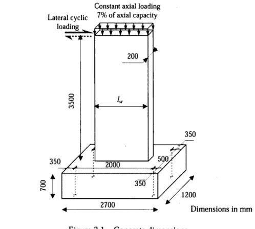
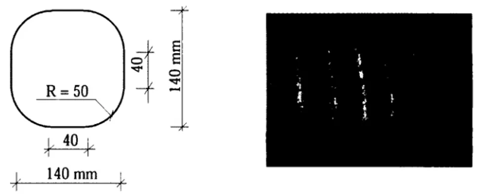
Figure 3.1 - Concrete dimensions 36
Figure 3.2 - Reinforcement details: elevation vie 38
Figure 3.3 - Reinforcement details: cross section 39
Figure 3.4 - Horizontal web reinforcement GFRP #4 (G15) 40
Figure 3.5 - Ties at boundary GFRP #3 (typical) 41
Figure 3.6 - Wall reinforcement cages 41
Figure 3.7 - Details of the base 42
Figure 3.8 - Design strain profile 43
Figure 3.9 - Formwork o f the base 49
Figure 3 .1 0 - The wall casting procedure 49
Figure 3 .1 1 - Test setup 50
Figure 3.12 - Dywidag bars fixing the base to the laboratory rigid floor 51
Figure 3.13 - Hydrolic jacks to apply constant axial load 51
Figure 3.14 - MTS actuator: lateral loading system 52
Figure 3 .1 5 - Lateral bracing system 52
Figure 3.16 - Applied displacement history 53
Figure 3.17 - LVDT instrumentation 54
Figure 3.18 - Strain gauges instrumentation 55
Figure 4.1 - Crack pattern 60
Figure 4.2 - Lateral load versus top-displacement relationship: ST15 62
Figure 4.3 - Failure progression o f specimen ST15 63
Figure 4.4 - Lateral load versus top-displacement relationship: G15 64
Figure 4.5 - Lateral load versus top-displacement relationship: G12 64
Figure 4.6 - Lateral load versus top-displacement relationship: G10 65
Figure 4.7 - Failure progression o f GFRP specimens 66
Figure 4.8 - Envelope curves: steel versus GFRP 67
Figure 4.9 - Envelope curves: aspect ratio 69
Figure 4 .1 0 - Energy dissipation versus top displacement 70
Figure 4 .1 1 - Energy dissipation versus residual force 71
Figure 4 .1 2 - Energy ratio: steel versus GFRP 71
Figure 4.13 - Energy ratio: aspect ratio 72
Figure 4.14 - Ratio of secant to initial stiffness 73
Figure 4.15 - Concrete strain 75
Figure 4.16 - Typical FE mesh (G 15) 77
Figure 4.17 - Hystertic response of FE: ST 15 78
Figure 4.18 - Hystertic response of FE: G15 78
Figure 4.19 - Hystertic response of FE: G12 79
Figure 4.20 - Hystertic response of FE: G10 79
Figure 4.21 - Typical crack pattern: experiment versus FE (G15) 80
Figure 4.22 - Typical failure mode: experiment versus FE (G15) 80
Figure 4.23 - ST15 Envelope curves: experiment versus FE 81
Figure 4.24 - G15 Envelope curves: experiment versus FE 82
Figure 4.25 - G12 Envelope curves: experiment versus FE 82
Figure 4.26 - G10 Envelope curves: experiment versus FE 82
Figure 4.27 - Curvature: experiment versus FE 83
Figure 4.28 - Rotation: experiment versus FE 84
Figure 5.1 - Calculation of average shear distortion 90
Figure 5.2 - Lateral load versus shear distortion relationship 91
Figure 5.3 - Decoupling flexure and shear deformations 93
Figure 5.4 - Flexural and shear deformation accounting for vertical displacement 94
Figure 5.5 - Idealized curvature and rotation 96
Figure 5.6 - Calculated curvature 98
Figure 5.7 - Calculated rotation 98
Figure 5.8 - Shear strain at ultimate load: experiment and FE 100
Figure 5.9 - Comparison of total displacement at h = 1„ 101
Figure 5.10 - Flexure and shear contribution to total displacement at h = /* 102
Figure 6.1 - Elastic and plastic deformations of shear walls 109
Figure 6.2 - Methods to estimate idealized load-displacement curves 117
Figure 6.3 - Idealized load-displacement curves for tested wall specimens 119
Figure 6.4 - Calculation of ductility-related response modification factor (Rd) 122
Figure 6.5 - Failure progression o f the tested wall specimens 125
Figure 6.6 - Definition o f plastic hinge length and analysis 126
Figure 6.7 - Moment-curvature response 130
Figure 6.8 - Normalized flexural secant stiffness 130
INTRODUCTION
1.1. General Background
Ensuring adequate stiffness in multistory buildings is important for resistance to lateral loads induced by wind or seismic events. Reinforced-concrete shear walls, which have high in-plane stiffness, have proven to provide excellent, cost-effective lateral resistance in comparison to other lateral-resisting systems (Cardenas et al. 1973, Wyllie et al. 1986, Fintel 1995). Compared to frame-type structures, shear-wall structures offer the advantages of less distortion and less damage to nonstructural elements.
That notwithstanding, climatic conditions under which large amounts of deicing salts are used during winter months generally hasten the corrosion of steel bars, causing deterioration of reinforced-concrete structures, especially bridges and multistory garages. Dealing with such conditions led to the need for alternative types of reinforcement to overcome corrosion problems. On the other hand, successful application of FRP-reinforcing bars as concrete reinforcement in a wide variety o f construction elements has reached an acceptable level (ACI 440 2007, fib Task Group 9.3 2007, ISIS Canada Design Manual No 3 2007). Because o f the advantages of FRP bars, they have found their way into numerous construction elements such as beams, one-way and two-way slabs, and, recently, columns (Kassem et al. 2011, Bakis et al. 2002, El-Salakawy et al. 2005, Sharbatdar and Saatcioglu 2009, Tobbi et al. 2012). Constructing a multistory building with adequate stiffness using FRP reinforcement calls for investigation into the behavior of shear walls totally reinforced with FRP. Unfortuntly, up to date, to the author’s knowledge, no investigation on adequately reinforcing shear walls with FRP have been done.
Therefore, this research intended to demonstrate that concrete shear walls reinforced with GFRP bars, as an alternative to steel bars, could achieve the reasonable strength and deformability requirements required in various applications.
1.2. Objectives and Scopes
This research project is the original experimental work on reinforcing shear walls with FRP bars. The test is in full-scale and aimed to experimentally approve the performance of concrete shear walls reinforced with glass-FRP bars, as an alternative to steel bars. The ability to achieve reasonable strength and deformability requirements is the main scope o f this study. Numerical simulation for the tested walls is also conducted to assess for the experimental results. The experimental results permitted to examine interaction between the flexure and shear deformation for such walls. Furthermore, the research addressed the issues of reversed cyclic loading behavior of GFRP-reinforced shear wall to propose seismic design recommendations.
The objectives of this study have been summarized as follows;
1. Design the tested GFRP-reinforced shear walls with an adequate amount of distributed and concentrated reinforcement to ensure flexural domination and eliminate sliding and shear brittle failures.
2. Examine the achieved drift and energy dissipation and comparing to the steel- reinforced wall. In addition, investigate the failure progression for such walls.
3. Evaluate the ultimate load capacity calculated based on the plane sectional analysis and finite element analysis.
4. Assess methods to calculate realistic, rather than conventional, flexural and sheaf deformations in shear walls controlled by flexure.
5. Identify the influencing key design factors affecting the behavior and ultimate capacity o f the GFRP-reinforced shear wall.
1.3. Methodology
These objectives relied on a comprehensive experimental program involving four shear walls; three GFRP-reinforced shear walls with different aspect ratios covering the range o f all medium-rise shear walls, and one steel-reinforced shear wall (as reference). The w alls’ dimension and reinforcements are detailed to the minimum requirements o f CSA A23.3 (2004), CSA S806 (2012), ACI 318 (2008), and ACI 440.1R (2006), when applicable.
The research program was conducted in a combined experimental and analytical study to achieve the research objectives through the following aspects;
1. Plane sectional analysis was carried out - based on actual material properties - to predict the ultimate lateral load of the tested walls. The analysis was based on strain compatibility, internal force equilibrium, and the controlling mode of failure.
2. Experimental study was conducted to examine strength and deformability of the proposed GFRP-reinforced shear walls subjected to quasi-static reversed cyclic loads.
3. The experimental results were analyzed regarding failure progression, strength, lateral drift and deformability, stiffness degradation, and energy dissipation.
4. Numerical simulations of the w all’s response were performed with two-dimensional finite element analysis program (VecTor2; W ong and Vecchio 2002) to predict the w all’s response under monotonic (push-over) and reversed cyclic loadings.
5. Based on the experimental and numerical simulation results, an attempt has been made to determine the effect o f each mode o f deformation on the total displacement of the wall specimens by separately calculating the flexural and shear deformations.
6. Propose a conceptual seismic design method for GFRP-reinforced shear walls based on the drift capacity of the wall.
1.4. Thesis Outlines
Chapter 1 o f this thesis presented background information on the research topic, the objectives of the research project, and the methodology that was adopted. Chapter 2 is the literature review reporting on past seismic experimental work on reinforced concrete shear walls in addition to background o f reinforcing with FRP bars. Details of the experimental program and the design o f the wall specimens are given in Chapter 3.
The subsequent three chapters respectively correspond to five technical papers that have either been accepted or submitted for publication in scientific journals:
Chapter 4 (Paper 1): Mohamed, N., Farghaly, A. S., Benmokrane, B., and Neale, K. W., 2013, “Experimental Investigation o f Concrete Shear Walls Reinforced with Glass-Fiber- Reinforced Bars under Lateral Cyclic Loading,” Journal o f Composites for
Construction, ASCE, (Accepted 6 M ay 2013).
Chapter 5 (Paper 2): Mohamed, N., Farghaly, A. S., Benmokrane, B., and Neale, K. W., 2013, “Flexure and Shear Deformation o f GFRP-Reinforced Shear W alls,” Journal o f
Composites for Construction, ASCE, (Accepted 25 September 2013).
(Paper 3): Mohamed, N., Farghaly, A. S., Benmokrane, B., and Neale, K. W., 2013, “Numerical Simulation of Mid-Rise Concrete Shear Walls Reinforced with GFRP Bars Subjected to Lateral Displacement Reversals,” Engineering Structures, Elsevier (submitted 19 September 2013)
Chapter 6 (Paper 4): Mohamed, N., Farghaly, A. S., Benmokrane, B., and Neale, K. W., 2013, “Drift Capacity Based Design for GFRP-Reinforced Shear Walls: Seismic Parameters,” A C I Structural Journal, (submitted 22 May 2013).
(Paper 5): Mohamed, N., Farghaly, A. S., Benmokrane, B., and Neale, K. W., 2013, “Drift Capacity Based Design for GFRP-Reinforced Shear Walls: Design Concept,”
A C I Structural Journal, (submitted 22 May 2013).
The content of these three chapters can be summarized as follows:
Chapter 4 addresses the applicability o f reinforced-concrete shear walls totally reinforced with GFRP bars to attain reasonable strength and drift requirements as specified in different codes. The reported test results clearly show that properly designed and detailed GFRP- reinforced walls could reach their flexural capacities and achieving a maximum drift meeting the limitation o f most building codes. Acceptable levels o f energy dissipation, compared to the
steel-reinforced wall, were observed. The promising results can provide impetus for constructing shear walls reinforced with GFRP and constitute a step toward using GFRP reinforcement in such lateral-resisting systems.
Chapter 5 investigates the interaction of flexural and shear deformations o f tested shear walls. Finite element simulation is conducted and the analyses captured the main features of behavior. It was found that relying on the diagonal transducers tended to overestimate shear distortions by 30% to 50%. Correcting the results based on the use o f vertical transducers was assessed and found to produce consistent results. Decoupling the flexural and shear deformations is discussed. Using elastic material gave uniform distribution of shear strains along the shear region, resulting in shear deformation ranging from 15% to 20% o f total deformation. The yielding of the steel bars intensified the shear strains at the yielding location, causing significant degradation in shear deformation ranging from 2% to 40% of total deformation.
Chapter 6 summarizes the design principles for steel reinforced shear walls for drift capacity and ductility o f shear walls. Primary guidelines for seismic design of a slender FRP-reinforced shear wall in moderate earthquakes regions is presented. The procedure can be used to design FRP-reinforced wall to have adequate drift capacity limited to shear walls dominated by a flexural failure mode. Evaluations of experimental tests assessed the design procedure and provided a proposed value for force reduction factor. This study also presents a critical review of the assumptions that were used to calculate ductility in FRP members and the need for more reasonable ductility index for evaluation of the ductility o f FRP reinforced concrete sections.
The last Chapter of the thesis, Chapter 7, presents a general conclusion of the results obtained from the experiments and analyses with respect to the problems and observations discussed throughout the thesis in addition to recommendation for future work.
LITERATURE REVIEW
2.1. Reinforcing with FRP Bars
Fiber reinforced polymer (FRP) reinforcement is one o f the most promising new developments for concrete structures. The application o f FRP reinforcement is becoming increasingly important in construction industry as well as having great potential in many areas. FRPs offer the designer an outstanding combination of properties not available in other materials. The use of these composites for special applications in construction is highly attractive and cost effective due to improved durability, reduced life cycle maintenance costs, saving from easier transportation and improved on-site productivity, and low relaxation characteristics. In addition, fatigue strength as well as fatigue damage tolerance o f m any FRP composites are excellent. Because of their advantages over conventional materials, FRPs have found their w ay into numerous construction applications (Erki and Rizkalla 1993).
One of the main issues that have to be examined is the strength and deformability o f concrete shear walls reinforced with FRP bars, due to the linear stress-strain behavior of the FRP reinforcements. Therefore, as studying FRP-reinforced concrete shear walls, the properties of FRP bars should be discussed.
2.2. Types of FRP Bars
Since the early applications, many FRP materials with different types o f fibers have been developed (Figure 2.1). These fibers include aramid, carbon and glass fibers. The main affecting properties investigated to achieve the best FRP bar for longitudinal and transverse reinforcement o f shear walls are; tension, compression, shear, deformability, and anchorage properties.
Glass fibers are the most common FRP bars o f all reinforcing fibers. GFRP bars are available in different sizes, ranging from 6 mm to 25 mm in diameter; i.e. from No.2 to No.8 bars.
GFRP bars have a sand coated external layer, a mold deformation layer, or a helically wound spiral fiber layer, to create rough surface. The longitudinal strength of GFRP bars is bar size dependent; due to the material used in deferent bar size and shear lag. The strength of GFRP decreases as the diameter increase. The tensile strength of GFRP bars range between 675- MOO MPa. While the modulus of elasticity is ranging from 40 GPa to over 60 GPa, and the ultimate strain is in range 1.3 - 2.1%.
Glass-fiber-reinforced-polymer (GFRP) bar is a viable option as reinforcement in concrete structures, particularly when corrosion resistance or electromagnetic transparency is sought. However, the behavior o f GFRP bar in compression members is a relevant issue that still needs to be addressed.
The principal advantages of GFRP bars are (1) low cost, (2) high tensile strength, (3) high chemical resistance, and (4) excellent insulating properties. Notwithstanding, the disadvantages are (1) relatively low tensile modulus that can be as low as 1/3 of the value of carbon-FRP, (2) GFRP bar is sensitive to abrasion, (3) GFRP bar has relatively low fatigue resistance in comparison with the CFRP bar, (4) GFRP bar may suffer from alkalinity.
2.3. Properties of FRP Bars
2.3.1. General
FRP materials are anisotropic and are characterized by high tensile strength with no yielding only in the direction of the reinforcing fibers. This anisotropic behavior affects the shear strength and dowel action o f FRP bars, as well as their bond performance. Design procedures should account for a lack of deformability in concrete reinforced with FRP bars. The RC member reinforced with FRP bars is designed based on its required strength and then checked for serviceability and ultimate state criteria (e.g. crack width, deflection, fatigue and creep rupture endurance). In many instances, serviceability criteria may control the design.
The effects of the differences in mechanical characteristics of FRP and steel had to be considered, when considering FRP as reinforcements during cyclic loading as case in wind and earthquakes. These differences include FRP’s lack of ductile behavior from the essentially linear elastic stress-strain relationship o f the materials until rupture, lower modulus of elasticity, and higher ultimate strength, resulting in significantly different stiffness, damping, and hysteretic behavior in dissipating seismic energy. Besides, considerations had to be given on using high amount o f FRP may lead to brittle failure which is unfavorable in reinforced concrete structures.
2.3.2.Tensile Strength
The most important mechanical property of FRP bars is their axial tensile strength. Generally, various factors affect the tensile strength o f FRP bars. The most significant factors are fiber- volume friction that is defined as the ratio of the volume of fiber to the overall volume o f the bar over the unit length. Bar manufacturing process, quality control and rate o f resin curing also affect tensile strength (ACI 440.1R 2006). Moreover, the tensile strength is function of FRP diameter. Due to shear lag, fibers located near the center of cross section are not subject to the same stress as those fibers oriented near the outer surface of FRP (ACI 440.1R 2006). This phenomenon results in reduced strength and efficiency in larger diameter bars where FRP bars may fail by one of the following failure modes; (1) tensile rupture o f fibers, (2) matrix
tensile rupture causing separation o f the fibers from the matrix, (3) combination of fiber/matrix interfacial shear failure, (4) matrix shear failure causing longitudinal splitting (debonding along the fiber/matrix interface).
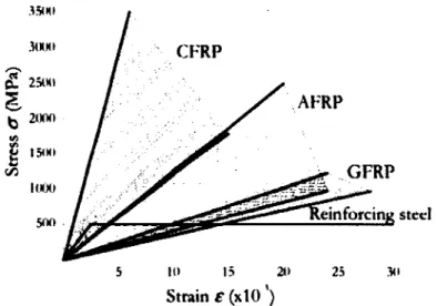
The tensile behavior of FRP is characterized by a linear elastic stress-strain curve up to failure (Figure 2.2). Linear elastic response up to failure with low failure strains, a lack in yield plateau with a general lack of ductility, brittle failure, very high tensile strength and relatively low modulus o f elasticity, these are the main mechanical properties o f FRP bars. Table 2.1 shows typical tensile properties of different FRP bars compared with steel bar properties.
CFRP
A FRP
GFRP
5 10 15 21) 25
Strain
e
(xtO')Figure 2.2 - Stress-strain curves o f FRP and steel materials
Table 2.1 - Usual tensile properties o f reinforcing bars (ACI 440.1R-06)
Properties Steel GFRP CFRP AFRP
Yield stress MPa 276 to 517 N/A N/A N/A
Tensile strength MPa 483 to 690 483 to 1600
600 to 3690
1720 to 2540
Elastic modulus GPa 200 35 to 51 120 to 580 41 to 125
Yield strain % 0.14 to 0.25 N/A N/A N/A
2.3.3. Compressive Strength
Design parameters in compression are not addressed since the use of FRP rebars in this instance is discouraged in many codes. Except for JSCE, current guidelines and codes of practice such as ACI 440 and CSA S6-06 (CHBDC), do not recommend the use of FRP bars as reinforcement in compression. Meanwhile, few studies stated that columns reinforced with GFRP bars behaved very similar to the conventional steel reinforced columns (Tobbi et al. 2012). Mallick (2008) concluded that the compressive strength of GFRP bars was found 55% lower than the tensile strength and the compressive modulus of elasticity o f GFRP bars was approximately 80% of the tensile modulus.
Kobayashi and Fujisaki (1995) tested AFRP, CFRP, and GFRP bars in compression. The ends of specimens were cast in concrete blocks and the unbraced length was 5 mm. Experimental results showed that the compressive strengths of the AFRP, CFRP, and GFRP rebars were 10, 30-50, and 30-40% of their tensile strengths, respectively. Meanwhile, when using grid type GFRP, it showed almost the same capacity as tensile capacity. In addition, FRP bars under reversal cyclic loading experimental work take place in range between 85% of tensile strength and 85% o f compressive strength under one w ay loading a maximum of 10-30 reversed cycles. The experimental results showed that, the compressive strength o f the GFRP and AFRP rebars were significantly reduced under cyclic loads, where a reduction o f 20-50% of compression capacity was observed. While CFRP bars showed no influence of cyclic loading.
Deitz et al. (2003) tested forty five GFRP ribbed bars with different lengths under compression. The ends o f the specimens were partially restrained with a threaded steel rod. The experimental results showed that there were three distinct failure modes depending on the unbraced length. The first failure mode was a crushing failure o f separating glass fibers from the resin matrix and buckled individually. This failure mode was observed for bars with unbraced length 50-110 mm. This mode of failure gave wide scatter results o f ultimate compressive strength with minimum o f 50% of the ultimate tensile strength. The second failure mode was pure buckling were the resin matrix and fibers buckled as a single entity. This failure was exhibited by specimens with unbraced length from 210 to 380 mm and resulted in compressive strength much lower than the first failure mode depending on the
buckling length. The third failure mode was for specimens with length ranging from 110 to 210 mm and failed in a combination of crushing and buckling.
Alsyaed et al. (2000) investigated the effect of replacing longitudinal and transverse steel bars by equal amount of GFRP in columns. It was reported that longitudinal GFRP reduced the axial capacity of columns by 13% average. In case of replacing steel stirrups with GFRP, irrespective to the type of longitudinal reinforcement, reduced the axial capacity o f columns by about 10%, and had no influence on load-deflection response o f columns up to 80% o f the column ultimate capacity.
De Luca et al. (2009) presented an experimental testing of five full-scale square GFRP and steel reinforced concrete columns under pure axial load. The results showed that, the average stress reached about 90% o f average concrete strength when the maximum load was reached. Also it was reported that the tie spacing played a relevant role in term of ductility. Brittle failure was observed with 305 mm tie spacing GFRP, while with 76 mm tie spacing the failure mode was ductile. The failure mechanism was initiated by vertical cracks, followed by lateral deflection of vertical bars resulting in spoiling of the concrete cover, then by crushing of concrete core and fracture of vertical reinforcing bars.
2.3.4. Flexure Properties
Although the flexural strength value is based on the maximum tensile stress, it does not reflect the true tensile strength of the material, i.e. there are difference between tensile strength and flexural strength o f FRP bar. This is due to several considerations, first is that the maximum fiber stress may not always occur at the outermost layer of the bar, which may cause splitting between fiber layers. Besides, under flexure, normal stress and shear stress are both presented, and shear can be quite significant in FRP bars which can reduce the flexure resistance of bar. Compared with a steel-reinforced section with equal areas o f longitudinal reinforcement, a cross section using FRP flexural reinforcement after cracking has a smaller depth to the neutral axis because o f the lower axial stiffness, which is because of reinforcement area and the lower modulus of elasticity. Therefore, the compression region of the cross section is reduced, and the crack widths are wider.
Failure o f flexural member reinforced with FRP can be caused by FRP rupture or concrete crushing (CSA S806-12). FRP reinforced member under flexure loads behave similar to the conventional steel reinforced one. According to designing codes, FRP reinforced flexural member may be designed using the ultimate design method for over reinforced sections, assuming plane section remains and full compatibility between concrete and FRP bars. However, the deflection at service loads and crack width may control the design. ACI 440.1R (2006) recommends a large amount of FRP reinforcement to be provided in the tension zone of flexural members in order to obtain compression failure mode which is the most ductile failure mode, as well as, for controlling crack width and deflection. CSA S6 (2006) recommends that the moment of resistance of flexure member cross section reinforced with FRP should be at least 50% greater than the cracking moment, to avoid brittle failure.
2.3.5.Shear Properties
Typical shear failure modes that can occur in steel-reinforced concrete members are diagonal tension failure, shear compression failure, and failure by crushing o f the concrete struts. The FRP shear elements can fail due to either a dowel action rupture or a concentration o f stress at a corner .in the reinforcement (Hegger et al. 2009).
Zhao et al. (1995) argued that flexural capacity o f FRP reinforced beams can be predicted by the ordinary beam theory, however, the shear behavior of these beams are different from those reinforced with steel reinforcement. Besides, using design equations taking into account o f the ratio of the elastic modulus of FRP to that o f steel cannot be applied to the stirrup contribution because FRP does not show the yield phenomenon. The experimental investigation done by Zhao (1995) shows that, when shear compression failure was dominant, the higher stiffness o f stirrups resulted in higher shearing capacity with smaller stirrup stain at the ultimate.
Guadagnini et al. (2006) conducted twelve steel and FRP reinforced beams with different shear span to depth ratios to investigate the shear behavior of beams. The main conclusion was that similar shear failure modes were developed in GFRP reinforced beams and in steel reinforced beams, suggesting that the shear carrying mechanisms are mobilized in a similar
manner. Furthermore, maximum strain values, ranging from 10,000 pa to 20,000 pe for GFRP and 8,000 pe to 10,000 pe for CFRP, were recorded in the shear reinforcement.
CSA S6 (2006) and ACI 440.1R (2006), both design the FRP-reinforced concrete member similar to that of steel-reinforced concrete members by Vr=Vc+Vsl where both aggregate interlock and dowel action are neglected. Vst = Vs or Vfrp shear force resisted by stirrups according to the type of stirrups. In CSA S6 (2006), Vcis same as for steel reinforced section multiplied with the ratio of the elastic modulus of FRP to that o f steel. While in ACI 440.1R (2006), Vc is modified by the factor ([5/2] A), which accounts for the axial stiffness o f the FRP reinforcement. Vfrp is calculated by limiting the stresses in FRP shear reinforcement to control shear crack widths and maintain shear integrity o f the concrete and to avoid failure at the bent portion. The stress in FRP was depending on the stirrup diameter or the tail length or the reinforcement ratio o f longitudinal reinforcement.
2.3.6. Fatigue Properties
The fatigue properties of a material represent its response to cyclic loading, which in common occur in many applications. It is well known that any material lost its strength under cyclic load. The cycle to fail depends on different variables such as stress level, stress state, mode of cycling, process history, material composition, and environment conditions. The fatigue process in FRP involves several damage modes, including fiber/matrix debonding, matrix cracking, delamination and fiber fracture. The elastic properties o f FRP, in particular the stiffness, are affected by this fatigue damage and are gradually decreased.
The fatigue behavior of fiber reinforced composites is quite different from the one imposed by metals, which fatigue failure generally occurs by the initiation and propagation of a single crack. Fatigue damage can start very early after a few hundred of loading cycles (Mallick 2008). Due to the stiffness degradation, load is transferred from damaged areas to neighboring undamaged areas and hence stress redistribution occurs and accordingly degradation in residual strength takes place. In a later stage more serious types of damage appear, such as fiber breakage and unstable delamination growth, leading to accelerated decline and final failure.
Katz (1998) studied the behavior of helically-wrap GFRP subjected to tension, the results showed that the fiber could develop tension or compression stresses under tensile load, depending on the winding step size of the helical fiber and the Poisson coefficient of the rod. When the rod was subjected to cyclic loading, extensive damage was caused to the longitudinal fibers by lateral load imposed by the helical fiber, which led to a premature failure o f the rod. An experimental study on the fatigue behavior of helically-wrap GFRP rods showed that the longitudinal fibers in the region underneath the helical fiber fractured locally by local failure of the longitudinal fibers directly under the helical ones, while the other fibers in the core rupture in various lengths under direct tension. Other types of rods, without helical wrapping, survived large numbers of cyclic loadings without failure. Paepegem and Degrieck
(2004) reported that tensile loading is less serious than compressive one, as fibers support the majority of the applied load. In compression, damage was observed due to local buckling.
2.3.7. Deformability
Deformability is important to ensure large deformations and providing warning o f impending failure and is obviously important in seismic where the ability to absorb energy is o f prime importance. Deformability is a measure of how much deformation or strain a material can withstand before breaking.
In steel reinforced structures, deformability (ductility) is defined as the ratio o f post yield deformation to yield deformation which it usually comes from steel. Due to the linear-strain- stress relationship of FRP bars, the traditional definition of deformability can not be applied to structures reinforced with FRP reinforcement. Several methods, such as the energy based method and the deformation based method have been proposed to calculate the deformability index for FRP reinforced structures; as follows:
2.3.7.1.
Energy based approach
In this approach, deformability is defined as the ratio between the elastic energy and the total energy. Naaman and Jeong (1995) proposed the following equation to compute ductility index
(2.1)
where E, is the total energy computed as the area under the load deflection curve; and Ee is the elastic energy. The elastic energy was computed as the area of the triangle formed at failure
D isplacem ent
Figure 2.3 - Naaman and Jeong’s definition of deformability index
2
.3
.7
.2
.Deformation based approach
The deformation based approach was first introduced by Jaeger et al. (1995). It takes into account the strength effect as well as the deflection (or curvature) effect on the deformability. Both the strength factor and the deflection (or curvature) factor are defined as the ratio of moment or deflection (or curvature) values at ultimate to the values corresponding to the concrete compressive strain o f 0.001. The strain o f 0.001 is considered the beginning of inelastic deformation o f concrete.
deformability factor = strength factor x deflection (or curvature) factor
load by a line having the weighted average slope of the two initial straight lines o f the load deflection curve, as shown in Figure 2.3.
•OA S= [P,s,+ (P2-Pi) S2] / P 2
Q n _ it . u
strength factor = moment at ultimate
moment at concrete strain of 0.001
deflection factor = deflection at ultimate deflection at concrete strain o f 0.001
curveture at ultimate curvature factor = ---
---curveture at concrete strain of 0.001
Tighiouart et al. (1998) found that the deformability indices computed by the curvature factor demonstrated more consistent comparison to those computed by deflection factor. Although there are different ways to calculate the deformability index, deformability can no doubt be defined as the ability to absorb the inelastic energy without losing its load capacity.
CSA S6 (2006), based on the work of Jaeger et al. (1995) assesses the deformability o f FRP- strengthened sections with a performance factor equal to
^
0.00100.001where M and 0 are the beam moment and curvature and the subscripts u refer to the ultimate state, and 0.001 refer to the service state that corresponds to a concrete maximum compressive strain o f 0.001. This performance factor must be greater than 4 for rectangular sections and greater than 6 for T-sections.
W ang and Belarbi (2005) argued that to increase the deformability of beams reinforced with FRP bars by two approaches, one is by using hybrid FRP rebars, which were found in previous studies that their deformability index are close to that of beams reinforced with steel, but this approach is limited in application due to its complicity and high cost o f manufacturing. The other approach is to improve the property of concrete with use o f over reinforcement so that failure is in concrete crush rather than by bar rupture.
Sharbatdar and Saatcioglu (2009) and Deitz et al. (2003) suggested different approach to prevent brittle failure. By designing concrete sufficiently confined and the section is over reinforced with FRP bars, this allows concrete crushing at ultimate prior to the tension failure of FRP, as opposed to conventional design concept used for steel reinforced sections, and satisfy more ductility to the member.
The fib (2001) notes that, if the design is governed by the serviceability limit state (SLS), the amount o f FRP provided to the structure may be considerably higher than what is needed for
the ultimate limit state (ULS). In this case, it may be difficult to fulfill deformability requirements.
2.3.8. Damping
The damping property o f a material represents its capacity to reduce the transmission of vibration caused by mechanical disturbances to a structure. Fiber reinforced composites, in general, have a higher damping factor than metals. However, its value depends on a number of factors, including fiber and resin types, and stacking sequence. Damping is measured by damping factor; r\\ a high value of r\ is desirable to reduce the amplitude o f vibration in structure. GFRP has damping factor equal, r\ = 0.0070, while CFRP damping factor equal; v\ = 0.0157 (Mallick 2008).
2.4. Steel-Reinforced Shear Walls
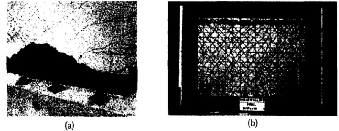
Concrete structural walls provide a cost effective way to resist lateral loads generated by wind and earthquakes and thus they are frequently incorporated as the primary lateral load resisting system in buildings. Structural walls have a high in-plane stiffness, which helps decreasing the structural damage by limiting the drift during seismic events. M any researchers, Fintel (1995) and Paulay (1988), reported excellent earthquake performance o f shear wall type building structures. Compared to frame-type structures, advantages o f shear wall structures were less distortions and less damage on non-structural elements that reinforced walls have the capacity to withstand severe earthquakes. These claims were substantiated by observations from post earthquake investigations such as in Chile 1985 minor damage due to extensive use o f non- ductile shear walls was observed; Wyllie et al. (1986), as shown in Figure 2.4.
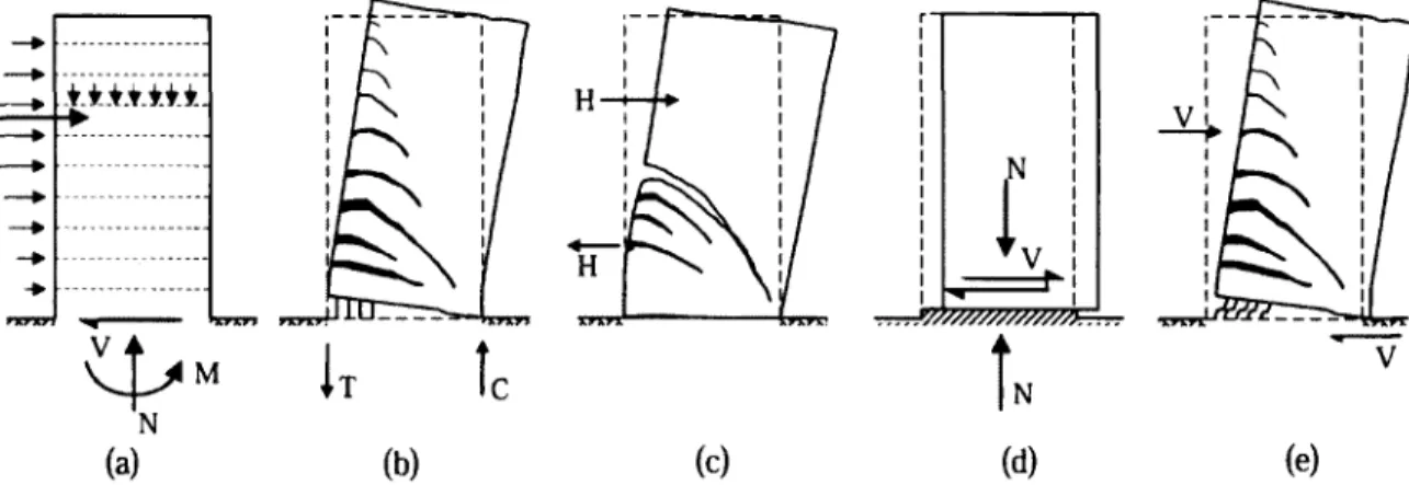
In seismic design of buildings, the life safety of the occupants is o f vital importance. For loads representative of wind or small frequent earthquakes, steel-reinforced shear walls are typically designed to respond in an elastic manner. However, during larger, less frequent earthquakes, the shear walls in seismic regions are required to resist lateral loads while deforming in a ductile manner (i.e., allowing the wall to deform beyond its yield limit without experiencing any significant reduction in strength), thereby dissipating seismic energy imparted by an earthquake and preventing structural collapse. The ductile response o f an RC structure can be ensured, by allowing it to response in a manner dominated by inelastic flexural yielding o f carefully detailed plastic hinges and inhibiting other non-ductile failure modes such as shear failure (i.e., diagonal tension or compression failure), sliding failure, and bond failure of reinforcement in lap splices. In order to study the behavior o f shear walls and its failure modes, a review of affecting parameters on shear wall behavior will be discussed as it relates to wall response.
2.5. Parameters Affecting Shear W alls Strength
To study the Shear wall behavior requires identification of the parameters that influence wall behavior. These parameters will be discussed, also their effect on mechanism of load resistance, and failure modes.
2.5.1. Wall Aspect Ratio
One of the main governing parameters of shear wall behavior is the aspect ratio which is simply defined as the height-to-length ratio (/>„//*). In moderate or high rise buildings, tall walls are used and can be treated as ordinary reinforced concrete cantilever beam-column. In such steel reinforced walls it is relatively easy to ensure developing adequate ductility as flexural behavior is dominated. In low rise buildings, squat wall type is used. These are characterized by a small height-to-length ratio h»/lw. The potential flexural strength of such walls is large in comparison to lateral forces. Because of small height, relatively large shearing forces must be generated to develop the flexural strength at the base. Therefore, the behavior of squat shear wall is dominated by shear as they are strongly affected by shear, and have more difficulty developing the required energy dissipation. This is due to high shear forces
associated with low aspect ratios may result in diagonal tension, compression or sliding shear failures prior to development of flexure capacity. Shear failure in walls is a brittle failure mode and reduce inelastic deformability, which is essential in energy dissipation.
A large proportion of the walls constructed in the U.S. and Canada are classified as medium- rise walls; with wall height-to length aspect ratios { h ^ Q typically between 2 and 4 (Jiang and Kurama 2010), where both nonlinear flexural and nonlinear shear deformations significantly contribute to the lateral response.
2.5.2. Boundary Element
Boundary elements are often presented to allow effective anchorage o f transverse beams. Even without beams, they are often provided to accommodate the principal flexural reinforcement, to provide stability against lateral buckling, and to enable more effective confinement of the compressed concrete in potential plastic hinges. Boundary elements may consist of concentrated reinforcement at ends o f walls or may be flanged walls. Flanged walls are shown to exhibit ductility to web walls when flanged walls are in compression. Code provisions give limits for the effective width o f flanged walls to be considered effective. Meanwhile, concentrated reinforcement boundary elements are often used in shear walls which prevent possible instability especially where yield of reinforcement and high compressive strains in concrete are expected; i.e. hinge regions at both ends of the wall.
Boundary elements may act as a frame with the shear wall which influences the load carrying capacity, the failure mode and the behavior of shear wall. This frame action was investigated to provide a mode of failure that was gradual rather than sudden or catastrophic.
2.5.3.Construction Joint
Horizontal construction joints in shear wall may become the weakest link in the chain of resistance and is considered a poor energy dissipater. From previous experimental works it was found that, the possibility of failure by sliding shear is feature of shear walls, especially with construction joints poorly prepared, as large shear stresses were transferred across crack
by means of shear friction (Paulay 1977). Accordingly, construction joints are subject to axial compression or tension and bending moments beside shear forces. Therefore, to ensure structural resistance o f walls and ensure energy dissipation, it is relevant to provide sufficient reinforcement across a construction joint (Paulay 1977).
2.5.4. Horizontal and Vertical Reinforcement
It is recommended in different codes; CSA and ACI, which minimum horizontal reinforcement should be provided, although the horizontal reinforcement does not contribute to shear strength in walls with aspect ratio 0.5 and less, however, the horizontal reinforcement and the vertical reinforcement are effective in producing more distributed cracking pattern and in reducing crack width (Barda et al. 1977). Moreover, transverse reinforcement is a main parameter that affects confinement of the shear w all’s web. According to widely held research, increasing the ratio o f transverse reinforcement increases both strength and ductility of confined concrete.
2.5.5. Foundation of Shear Walls
One o f the most critical regions o f shear walls is the base o f the wall. The foundation must be capable of resisting the associated overturning moment. In order to provide adequate design for such foundations, there are basic problems must be taken into considerations;
• Anchorage of shear wall: the shear wall had to be well anchored to the foundation to resist sliding shear and overturning effects due to lateral loads on the wall.
• Overturning on foundation: this had to be taken into consideration by performing the analysis o f overturning moment with the safety factors resulting from the dead loads and passive soil pressure.
• Horizontal sliding: had to be resisted by foundation.
2.6. Behavior of Shear Wall
Shear walls under quasi-static cyclic lateral loading exhibit behavior that is different from those of beams, columns, and deep beams. The difference stems from geometry, boundary condition, and loading. Shear walls differ from columns as they are generally thin members that may be classified according to the shear span of either beam or deep beam. Meanwhile shear walls differ from beams and deep beams as loads applied are normally distributed along floor lines and not concentrated at certain points as the case of beams or deep beams.
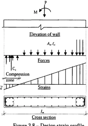
2.6.1. Flexure Behavior
Flexural behavior o f wall, representing in Figure 2.5, under combined flexure and axial forces has two equilibrium equations; Eq. 2.3 and Eq. 2.4, and a strain compatibility relationship; presented in Eq.2.5, to enable flexural strength to be determined. The approach for walls is generalized by the three equations from 1 to n layers o f reinforcement. However, if the neutral axis is in the web rather than the boundary element, the center of compression o f Cc will not be at mid-depth o f equivalent rectangular compression stress block. If much higher compression strain is required to exhibit more ductility, concrete cover in compression region had to be ignored when analyzing to obtain flexural strength.
Cc + £ 4 , f Si = P, w h e r e Cc - a f c'ab (2.3) M , = C c c — 2 + E 4 , 4 (c- * , ) + ^ v2 — c / (2.4) e ,=£si cu c - X, (2.5)
As the distribution of reinforcement can not readily be represented when starting design procedure, this makes the calculation of flexural strength o f walls more tedious than beams and columns. Therefore, flexural strength of walls is often estimated using design charts or using a computer program.
Boundary element M r
T
- v Elevation o f wall Boundary elementr z i
Cross section S tra in s ForcesFigure 2.5 - Equilibrium o f wall section under flexural and axial loads
It is considered that yielding o f the flexure reinforcement is a good source o f hysteretic damping. In high-rise walls, yielding can be restricted to the base o f the wall where plastic hinge may occur. However, concrete is a brittle material which should not normally be considered as a significant contributor to the energy dissipation. To ensure the desired ductility, internal forces in the potential plastic hinge region should be allocated to the reinforcement.
2.6.2. Shear Behavior
Shear strength of the shear wall may be seriously affected by the axial tension generated by induced overturning moment. The gravity load o f the wall may not be enough to suppress the induced internal tension and as a result diagonal cracks may form at an angle steeper than 45° to the vertical axis o f the wall. To ensure that premature diagonal compression failure will not occur in the wall before the onset yielding of shear reinforcement, the nominal shear stress needs to be limited, especially where cyclic effect and ductility demands must be taken into account (Paulay and Priestley 1995).
Shear strength of a wall is combination o f the contribution of concrete to shear strength (V,c) and contribution o f shear reinforcement (Ps), derived from;
V„=VC+VS (2.6)
The contribution o f concrete is defined as follows;
Vc= v cb d (2.7)
where vc is the concrete shear stress and is calculated as follows;
vc =0.27y[7^' + Nu/4Ag (2.8)
or in plastic hinge regions as follows;
vc = 0.6jN J A g (2.9)
The contribution o f shear reinforcement, based on truss models with 45° diagonal strut, is
Vs = A f y(d/s) (2.10)
Because flexural cracks and diagonal cracks usually merge, yielding o f the vertical reinforcement causes an increase o f the width of the diagonal cracks. Consequently a major component o f the shear resisting mechanism o f the concrete, aggregate interlock, diminishes and with the progressive of high intensity reversed cyclic loading, more shear is transferred to