Pépite | Développement d’un système de recommandation de vêtements intelligent orienté vers les consommateurs
190
0
0
Texte intégral
(2) Thèse de Haibo Zhang, Lille 1, 2017. © 2017 Tous droits réservés.. lilliad.univ-lille.fr.
(3) Thèse de Haibo Zhang, Lille 1, 2017. 献给我的父母和姐姐们 Dedicated to my parents and sisters. © 2017 Tous droits réservés.. lilliad.univ-lille.fr.
(4) Thèse de Haibo Zhang, Lille 1, 2017. © 2017 Tous droits réservés.. lilliad.univ-lille.fr.
(5) Thèse de Haibo Zhang, Lille 1, 2017. Acknowledgements This PhD work, done in the last three years in L2EP, is not only a result of my own dedication and perseverance, but also a credit to the kind and helpful people that I have worked with. I would like to express my gratitude to everyone who has supported me in the last three years. My appreciation starts with the valuable comments from the jury of my defense: M. Abdelkrim benchaib, M. Fabrice Locment, M. Florent Morel. I was very honored to invite the director of my laboratory L2EP, Mme. Betty Semail, to become the chairman of the jury. My special gratitude to Professor Jun Liang, who traveled to Lille from UK to participate my PhD defense. He had offered me to work with him for one month in the University of Cardiff. He is precise, efficient, trustful, and enlightened me in many technical problems. I would like to express my sincere gratitude to my PhD director, M. Christophe Saudemont, for accepting me as his first PhD student. He gave me a lot of freedom to understand this project, and put my ideas into practice. I also appreciate the contribution of my cosupervisor Mme. Diana M. Florez R. in my thesis. I am extremely grateful to M. François Gruson. He is always inspiring, and gave me very helpful advises during the last three years. Without him, this work would be much less attractive. With his recommendation, I had the opportunity to work in ENSAM, where I got to know other helpful researchers in my field. These memories are still fresh in my mind: M. Xavier Guillaud who taught me basic knowledges on power conversion in François’s office at the beginning of my PhD, M. Moez Belhaoune who helped me to revise my presentation slides in the last afternoon before my first year PhD defense, M. Frédéric Colas who helped a lot on the experimental tests, and many other great colleagues in ENSAM. Most of my unforgettable memories happened in the Room RR120 in the Maison de la Recherche of HEI. Many thanks to my friends and colleagues who had accompanied me over there: My best French teacher Jonathan, Iranian genius Siyamak, problem solver Fabien, Anouar, Faycal, Mouloud, Lounes, Amine, Géraldine, Sid-Ali and "his daughter" Loubna, gaucho Adrien, indispensable LiveTree engineers Gregoire and Benoit, Laura (Ah! Il n’y pas de chauffage!), Volahasina (Attention, Doritos Roulette), le grand chercheur Libanais Jad, Serbian talent Vojislav, and finally the great Chinese: Xing, Xingyu, Tuo.. I © 2017 Tous droits réservés.. lilliad.univ-lille.fr.
(6) Thèse de Haibo Zhang, Lille 1, 2017. II. Last but not least, I would like to give my infinite gratefulness to my parents and my sisters. They are the strongest support for me that give me confidence in overcoming any difficulties in my life.. © 2017 Tous droits réservés.. lilliad.univ-lille.fr.
(7) Thèse de Haibo Zhang, Lille 1, 2017. Abstract The massive exploitation of far offshore wind energy relies heavily on the High Voltage Direct Current (HVDC) transmission system, in which dedicated offshore substations for converting power from AC into DC are necessary. However, the bulky offshore platform is costly and its installation is complicated. In this frame, this thesis aims to contribute to the study of a pure DC offshore wind farm topology which exports its energy to onshore without using an offshore centralized power conversion substation. The examined wind farm topology is called Series Parallel Wind Farm (SPWF), which comprises several clusters of wind turbines connected in series, so that the output converters of the wind turbines step up the voltage to a higher level for direct power transmission. However, this distinctive feature of series connection evinces the unfeasibility of independent operation of the connected units. The output voltages of wind turbines depend not only on their own power production, but also on the power production of the entire cluster. As a consequence, unbalanced power production of wind turbines due to uneven wind speed distributed in the wind farm, leads to output voltage variation of wind turbines. Furthermore, the elimination of offshore substation merges the wind farm collection system and the HVDC transmission system, leaving a part of the system variables uncontrolled. The work carried out in this thesis begins with the identification of the basic elements to constitute the SPWF. Afterwards, the operation of the series connected wind turbines is explained and its overvoltage characteristic is described and emphasized. An overvoltage limitation control strategy is thus developed, which requires an active participation of the onshore converter in limiting the wind turbines output voltages. Hence, the onshore Multilevel Modular Converter (MMC) as well as the HVDC cables models are examined. The control strategy is applied to both Point-to-Point (P2P) HVDC transmission system and MultiTerminal DC (MTDC) systems. The results validate the feasibility of the proposed strategy and demonstrate its advantage of no power curtailment requirement to limit the wind turbines output voltage. Key word: Series Parallel Wind Farm (SPWF), Multilevel Modular Converter (MMC), HVDC transmission, Multi-Terminal DC (MTDC), Overvoltage limitation.. III © 2017 Tous droits réservés.. lilliad.univ-lille.fr.
(8) Thèse de Haibo Zhang, Lille 1, 2017. © 2017 Tous droits réservés.. lilliad.univ-lille.fr.
(9) Thèse de Haibo Zhang, Lille 1, 2017. Résumé L’énergie éolienne est très abondante lorsque l’on se situe à des distances éloignées des côtes maritimes. Toutefois, l’exploitation de la puissance électrique que l’on peut en tirer, peut nécessiter de recourir à des systèmes de transport de l’électricité en Courant Continu Haute Tension (HVDC). Ces systèmes nécessitent généralement la présence d’une sousstation située en mer (offshore), dédiée à l’adaptation de tension entre le réseau de distribution en mer (souvent AC) et le réseau de transport. Cette plateforme est volumineuse, son coût élevé et son installation compliquée. Cette thèse s’intéresse à une topologie de ferme éolienne offshore DC qui transporte son énergie vers l’onshore sans utiliser de sous-station offshore. Ce type de ferme éolienne est appelé Ferme Eolienne Série Parallèle (SPWF). Il est composé de plusieurs grappes d’éoliennes interconnectées en série, de sorte que cette interconnexion engendre directement un niveau de tension adapté à la tension du réseau HVDC. Cependant, la connexion en série implique un couplage en courant de ces éoliennes et par conséquence la tension de chacune d’entre elle n’est plus constante. Un déséquilibre de production d’énergie causé, par exemple, par une distribution disparate de la vitesse de vent dans la grappe d’éoliennes, conduit à des variations des tensions en sortie des éoliennes. Ces variations de tension peuvent, dans certains cas, engendrer des surtensions aux bornes d’une éolienne dans la grappe et éventuellement l’endommager. Une action sur la puissance produite par les éoliennes permet d’éviter ces surtensions mais elle réduit la production de la ferme. Une stratégie permettant de limiter les éventuelles surtensions en sortie des éoliennes, tout en maintenant la production d’énergie, est proposée et développée dans ce mémoire. Cette stratégie est d’abord validée dans un contexte de connexion point à point, en considérant une transmission HVDC basée sur des câbles DC et un Convertisseur Modulaire Multiniveaux (MMC) permettant de la connecter au réseau onshore. Dans un second temps, la ferme SPWF est intégrée dans des systèmes DC multi-terminaux (MTDC). Les résultats de simulation démontrent la faisabilité et la viabilité de la stratégie et montrent qu’aucune réduction de puissance n’est alors nécessaire pour limiter les tensions en sortie des éoliennes. Mots clés: Ferme Eolienne Série Parallèle (SPWF), Convertisseur Modulaire Multiniveaux (MMC), Courant Continu Haute Tension (HVDC), DC Multi-Terminaux (MTDC), Limitation de surtension.. V © 2017 Tous droits réservés.. lilliad.univ-lille.fr.
(10) Thèse de Haibo Zhang, Lille 1, 2017. © 2017 Tous droits réservés.. lilliad.univ-lille.fr.
(11) Thèse de Haibo Zhang, Lille 1, 2017. Contents Contents. VII. List of Figures. XI. List of Tables. XVII. List of Acronyms. XIX. List of Symbols. XXI. General introduction. 1. Background of the thesis . . . . . . . . . . . . . . . . . . . . . . . . . . . . . . . . . . . .. 3. Motivations . . . . . . . . . . . . . . . . . . . . . . . . . . . . . . . . . . . . . . . . . . . .. 3. Objectives and thesis outline . . . . . . . . . . . . . . . . . . . . . . . . . . . . . . . . .. 6. List of publications . . . . . . . . . . . . . . . . . . . . . . . . . . . . . . . . . . . . . . . .. 8. 1 State of the Art of Offshore Wind Power Systems. 11. 1.1 Introduction . . . . . . . . . . . . . . . . . . . . . . . . . . . . . . . . . . . . . . . .. 13. 1.2 Offshore wind turbine technology . . . . . . . . . . . . . . . . . . . . . . . . . . .. 14. 1.2.1 Wind turbine foundation . . . . . . . . . . . . . . . . . . . . . . . . . . . .. 14. 1.2.1.1. Fixed-bottom foundation technology . . . . . . . . . . . . . . .. 14. 1.2.1.2. Floating foundation . . . . . . . . . . . . . . . . . . . . . . . . .. 15. 1.2.2 Constructional design: horizontal vs vertical axis . . . . . . . . . . . . .. 16. 1.2.3 Aerodynamic basics of conversion of kinetic wind energy into mechanical energy . . . . . . . . . . . . . . . . . . . . . . . . . . . . . . . . . . . . .. 18. 1.2.3.1. Tip-speed ratio . . . . . . . . . . . . . . . . . . . . . . . . . . . .. 19. 1.2.3.2. Power coefficient . . . . . . . . . . . . . . . . . . . . . . . . . . .. 20. 1.2.3.3. Torque coefficient . . . . . . . . . . . . . . . . . . . . . . . . . .. 21. 1.2.3.4. Ideal power curve . . . . . . . . . . . . . . . . . . . . . . . . . .. 22. 1.2.3.5. Maximum power point tracking . . . . . . . . . . . . . . . . . .. 23. VII © 2017 Tous droits réservés.. lilliad.univ-lille.fr.
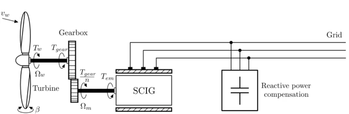
(12) Thèse de Haibo Zhang, Lille 1, 2017. VIII. CONTENTS. 1.2.4 Large commercial wind turbines . . . . . . . . . . . . . . . . . . . . . . . 1.2.4.1. 24. Squirrel Cage Induction Generator (SCIG) based fixed-speed wind turbine . . . . . . . . . . . . . . . . . . . . . . . . . . . . .. 26. Doubly Fed Induction Generator (DFIG) based wind turbine with partial-scale power converter . . . . . . . . . . . . . . . .. 27. Permanent Magnet Synchronous Generator (PMSG) based wind turbine with full-scale power converter . . . . . . . . . .. 28. Wind turbine with DC output . . . . . . . . . . . . . . . . . . .. 29. 1.3 Offshore power collection system . . . . . . . . . . . . . . . . . . . . . . . . . . .. 29. 1.3.1 MVAC collection system . . . . . . . . . . . . . . . . . . . . . . . . . . . . .. 30. 1.3.2 MVDC collection system . . . . . . . . . . . . . . . . . . . . . . . . . . . .. 30. 1.4 Power transmission system . . . . . . . . . . . . . . . . . . . . . . . . . . . . . . .. 32. 1.4.1 HVAC transmission . . . . . . . . . . . . . . . . . . . . . . . . . . . . . . .. 33. 1.4.2 HVDC transmission . . . . . . . . . . . . . . . . . . . . . . . . . . . . . . .. 35. 1.4.3 Other transmission methods . . . . . . . . . . . . . . . . . . . . . . . . . .. 37. 1.2.4.2 1.2.4.3 1.2.4.4. 1.4.3.1. LFAC transmission . . . . . . . . . . . . . . . . . . . . . . . . . .. 37. 1.4.3.2. Diode-based HVDC transmission . . . . . . . . . . . . . . . . .. 39. 1.5 Topologies of large wind farms . . . . . . . . . . . . . . . . . . . . . . . . . . . . .. 41. 1.5.1 Solution 1: MVAC-HVAC . . . . . . . . . . . . . . . . . . . . . . . . . . . .. 41. 1.5.2 Solution 2: MVDC-HVDC . . . . . . . . . . . . . . . . . . . . . . . . . . .. 42. 1.5.3 Solution 3: MVAC-HVDC. . . . . . . . . . . . . . . . . . . . . . . . . . . .. 42. 1.5.4 Solution 4: Series Parallel-HVDC . . . . . . . . . . . . . . . . . . . . . . .. 43. 1.5.5 Comparison of solutions . . . . . . . . . . . . . . . . . . . . . . . . . . . .. 43. 1.5.5.1. Cables cost . . . . . . . . . . . . . . . . . . . . . . . . . . . . . . .. 43. 1.5.5.2. Centralized converters and platforms . . . . . . . . . . . . . .. 44. 1.5.5.3. System Losses . . . . . . . . . . . . . . . . . . . . . . . . . . . . .. 44. 1.5.5.4. Energy availability . . . . . . . . . . . . . . . . . . . . . . . . . .. 45. 1.5.5.5. Consideration on the reliability of Series Parallel-HVDC solution . . . . . . . . . . . . . . . . . . . . . . . . . . . . . . . . . .. 46. 1.6 Conclusion . . . . . . . . . . . . . . . . . . . . . . . . . . . . . . . . . . . . . . . . .. 47. 2 Series DC wind farm basics. 55. 2.1 Introduction . . . . . . . . . . . . . . . . . . . . . . . . . . . . . . . . . . . . . . . .. 57. 2.2 Series connection of wind turbines . . . . . . . . . . . . . . . . . . . . . . . . . .. 57. 2.2.1 System Overview . . . . . . . . . . . . . . . . . . . . . . . . . . . . . . . . .. 57. 2.2.2 Steady state operation of series connection . . . . . . . . . . . . . . . . .. 59. 2.2.3 Definition of overvoltage . . . . . . . . . . . . . . . . . . . . . . . . . . . .. 60. © 2017 Tous droits réservés.. lilliad.univ-lille.fr.
(13) Thèse de Haibo Zhang, Lille 1, 2017. IX. CONTENTS. 2.3 Wind turbine generation and conversion systems . . . . . . . . . . . . . . . . . .. 62. 2.3.1 Power generation in the wind turbine . . . . . . . . . . . . . . . . . . . .. 62. 2.3.1.1. Mechanical part . . . . . . . . . . . . . . . . . . . . . . . . . . .. 62. 2.3.1.2. Permanent magnet synchronous generator . . . . . . . . . . .. 65. 2.3.2 High power DC/DC converter . . . . . . . . . . . . . . . . . . . . . . . . .. 67. 2.3.2.1. Full bridge converter . . . . . . . . . . . . . . . . . . . . . . . .. 68. 2.3.2.2. Control methods . . . . . . . . . . . . . . . . . . . . . . . . . . .. 69. 2.3.3 Output capacitor of the DC/DC converter . . . . . . . . . . . . . . . . . .. 72. 2.3.4 DC smoothing reactor . . . . . . . . . . . . . . . . . . . . . . . . . . . . . .. 73. 2.3.5 Insulation technology . . . . . . . . . . . . . . . . . . . . . . . . . . . . . .. 74. 2.3.6 Wind turbine unit fault and protection system . . . . . . . . . . . . . . .. 75. 2.3.7 Summary of the control system of the series connected wind turbine .. 77. 2.3.8 Wind turbine model simplification . . . . . . . . . . . . . . . . . . . . . .. 78. 2.4 Operation of a series connection . . . . . . . . . . . . . . . . . . . . . . . . . . . .. 78. 2.5 Overvoltage limitation methods . . . . . . . . . . . . . . . . . . . . . . . . . . . .. 81. 2.6 Conclusion . . . . . . . . . . . . . . . . . . . . . . . . . . . . . . . . . . . . . . . . .. 83. 3 Series wind farm in Point-to-Point HVDC transmission. 87. 3.1 Introduction . . . . . . . . . . . . . . . . . . . . . . . . . . . . . . . . . . . . . . . .. 89. 3.2 Modular Multilevel Converter (MMC) . . . . . . . . . . . . . . . . . . . . . . . .. 90. 3.2.1 Modelling of the MMC . . . . . . . . . . . . . . . . . . . . . . . . . . . . .. 92. 3.2.1.1. The 4 types of MMC models . . . . . . . . . . . . . . . . . . . .. 92. 3.2.1.2. Arm Average Model of MMC . . . . . . . . . . . . . . . . . . . .. 93. 3.2.2 Control of MMC . . . . . . . . . . . . . . . . . . . . . . . . . . . . . . . . .. 97. 3.2.2.1. Energy control arrangement of the MMC . . . . . . . . . . . .. 98. 3.2.2.2. Control system of the AC part . . . . . . . . . . . . . . . . . . .. 99. 3.2.2.3. Control system of the DC part . . . . . . . . . . . . . . . . . . .. 99. 3.2.3 Simulation of MMC . . . . . . . . . . . . . . . . . . . . . . . . . . . . . . . 101 3.3 Cable models . . . . . . . . . . . . . . . . . . . . . . . . . . . . . . . . . . . . . . . . 104 3.3.1 Resonant circuit SPWF-HVDC . . . . . . . . . . . . . . . . . . . . . . . . . 104 3.3.2 Wideband model reference in EMTP-RV library . . . . . . . . . . . . . . 105 3.3.3 HVDC cable models . . . . . . . . . . . . . . . . . . . . . . . . . . . . . . . 105 3.4 Global control strategy . . . . . . . . . . . . . . . . . . . . . . . . . . . . . . . . . . 111 3.4.1 Re-examination of the wind turbine output voltage . . . . . . . . . . . . 111 3.4.2 Basics of global control strategy . . . . . . . . . . . . . . . . . . . . . . . . 112 3.4.3 Global control strategy with bypass protection . . . . . . . . . . . . . . . 114. © 2017 Tous droits réservés.. lilliad.univ-lille.fr.
(14) Thèse de Haibo Zhang, Lille 1, 2017. X. CONTENTS. 3.4.4 Communication between the offshore wind farm and the onshore converter . . . . . . . . . . . . . . . . . . . . . . . . . . . . . . . . . . . . . . . . 115 3.4.5 Limitations of global control . . . . . . . . . . . . . . . . . . . . . . . . . . 117 3.4.6 Break-even voltage of the global control strategy . . . . . . . . . . . . . 119 3.4.6.1. Cable sizing & possibility of overcurrent by using global control119. 3.4.6.2. Break-even voltage . . . . . . . . . . . . . . . . . . . . . . . . . . 120. 3.5 Simulation of the global overvoltage limitation control . . . . . . . . . . . . . . 123 3.5.1 Case study . . . . . . . . . . . . . . . . . . . . . . . . . . . . . . . . . . . . . 123 3.5.2 Simulation results . . . . . . . . . . . . . . . . . . . . . . . . . . . . . . . . 126 3.6 Conclusion . . . . . . . . . . . . . . . . . . . . . . . . . . . . . . . . . . . . . . . . . 128 4 Series parallel wind farm in MTDC systems. 133. 4.1 Introduction . . . . . . . . . . . . . . . . . . . . . . . . . . . . . . . . . . . . . . . . 135 4.2 Series Parallel Wind Farm . . . . . . . . . . . . . . . . . . . . . . . . . . . . . . . . 135 4.2.1 Scaling of the SPWF . . . . . . . . . . . . . . . . . . . . . . . . . . . . . . . 136 4.2.2 Parallel connection of clusters . . . . . . . . . . . . . . . . . . . . . . . . . 136 4.3 SPWF operating in MTDC systems . . . . . . . . . . . . . . . . . . . . . . . . . . . 138 4.3.1 SPWF in a MTDC system with master-slave control . . . . . . . . . . . . 139 4.3.1.1. Characteristics of the MTDC system with master slave control 140. 4.3.1.2. Overview of the control strategy . . . . . . . . . . . . . . . . . 141. 4.3.1.3. Case study and simulation results of a hybrid three-terminal MTDC system . . . . . . . . . . . . . . . . . . . . . . . . . . . . . 142. 4.3.1.4. Operating points of the three-terminal MTDC system . . . . . 146. 4.3.2 SPWF in a MTDC system with droop control . . . . . . . . . . . . . . . . 146 4.3.2.1. Characteristics of the MTDC system with droop control . . . 147. 4.3.2.2. Overview of the control strategy . . . . . . . . . . . . . . . . . 149. 4.3.2.3. Case study and simulation results of a hybrid four-terminal MTDC system . . . . . . . . . . . . . . . . . . . . . . . . . . . . . 150. 4.3.2.4. Operating points of the four-terminal MTDC system . . . . . 152. 4.4 Conclusion . . . . . . . . . . . . . . . . . . . . . . . . . . . . . . . . . . . . . . . . . 153 5 Conclusions and perspectives. 157. 5.1 Conclusions . . . . . . . . . . . . . . . . . . . . . . . . . . . . . . . . . . . . . . . . . 159 5.2 Suggestions for future research work . . . . . . . . . . . . . . . . . . . . . . . . . 161. © 2017 Tous droits réservés.. lilliad.univ-lille.fr.
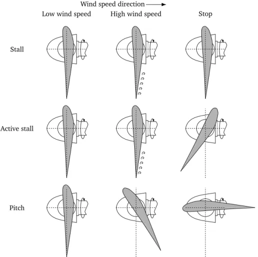
(15) Thèse de Haibo Zhang, Lille 1, 2017. List of Figures 1. WindEurope’s 20 Year Offshore Network Development Master Plan. . . . . . .. 4. 2. European map of wind speed extrapolated to 80 m in height and averaged over all days of the year 2000 at surface and sounding stations [Arch 05]. . .. 4. Kriegers Flak, a 400 MW offshore interconnection between two TSOs Energinet.dk from Denmark and 50Hertz from Germany [Krie 16a]. . . . . . . .. 5. Thesis outline divided into three levels of study. . . . . . . . . . . . . . . . . . .. 7. 1.1 General arrangement of an offshore wind farm. . . . . . . . . . . . . . . . . . .. 13. 1.2 Fixed-bottom foundations: monopile, tripod, jacket, gravity-based [Van 06].. 15. 1.3 Hywind 2.3 MW prototype deployed off the coast of Norway. . . . . . . . . . .. 16. 1.4 Floatgen floating project developed by IDEOL France. . . . . . . . . . . . . . . .. 16. 1.5 Main components of a HAWT and a φ-type VAWT [Hau 13]. . . . . . . . . . .. 17. 1.6 Offshore floating projects with VAWTs. . . . . . . . . . . . . . . . . . . . . . . . .. 19. 1.7 Characteristic of C p as a function of λ and β [Hau 06]. . . . . . . . . . . . . . .. 20. 1.8 Characteristic of C t as a function of λ and β [Hau 06]. . . . . . . . . . . . . . .. 21. 1.9 Performance curves of an ideal wind turbine. . . . . . . . . . . . . . . . . . . . .. 22. 1.10 Turbine mechanical power curves under different wind speeds. . . . . . . . . .. 24. 1.11 Wind turbine with stall control, active stall control, pitch control: view from blade tip to nacelle hub. . . . . . . . . . . . . . . . . . . . . . . . . . . . . . . . . .. 25. 1.12 SCIG-based fixed-speed wind turbine connected directly to the grid. . . . . . .. 26. 1.13 DFIG-based variable-speed wind turbine. . . . . . . . . . . . . . . . . . . . . . .. 27. 1.14 Variable-speed wind turbine using a PMSG and a full-scale power converter. .. 28. 1.15 General structure of a wind turbine for series connection . . . . . . . . . . . . .. 29. 1.16 Offshore wind farm "Banc de Guèrande" near Saint Nazaire, France. . . . . .. 31. 1.17 Offshore wind farm "Amrumbank West" at the German North Sea. . . . . . . .. 31. 1.18 Configuration of DC collection grid. . . . . . . . . . . . . . . . . . . . . . . . . . .. 32. 1.19 HVAC transmission for offshore wind farm. . . . . . . . . . . . . . . . . . . . . .. 33. 1.20 Distribution of shunt capacitors in a 3-core belted type AC cable. . . . . . . .. 33. 1.21 Distribution of shunt capacitors in three-phase single core HVAC cables. . . .. 34. 3 4. XI © 2017 Tous droits réservés.. lilliad.univ-lille.fr.
(16) Thèse de Haibo Zhang, Lille 1, 2017. XII. LIST OF FIGURES. 1.22 Transmission capabilities of HVAC with variation of the cable length. . . . . .. 35. 1.23 Cost of HVAC versus HVDC transmision. . . . . . . . . . . . . . . . . . . . . . . .. 36. 1.24 Transmission limitation of HVAC and HVDC offshore wind farms (green dots). 36 1.25 HVDC transmission for offshore wind farm.. . . . . . . . . . . . . . . . . . . . .. 36. 1.26 LFAC transmission for offshore wind farm. . . . . . . . . . . . . . . . . . . . . .. 38. 1.27 Point-to-Point HVDC link based on diode rectifier. . . . . . . . . . . . . . . . . .. 40. 1.28 Improved Point-to-Point HVDC link based on a hybrid offshore converter which comprises a diode rectifier and a VSC. . . . . . . . . . . . . . . . . . . . . . . . .. 40. 1.29 DC grid topology based on diode rectifier transmission proposed by Siemens [Flye 15]. . . . . . . . . . . . . . . . . . . . . . . . . . . . . . . . . . . . . . . . . . .. 41. 1.30 Wind farm topologies for long distance transmission. . . . . . . . . . . . . . . .. 42. 1.31 Power losses of 4 wind farm topologies. . . . . . . . . . . . . . . . . . . . . . . .. 45. 1.32 Power production of a series-parallel offshore wind farm with different control strategies after one wind turbine is bypassed. . . . . . . . . . . . . . . . . . . . .. 46. 2.1 Series connected wind turbines with DC output voltages. . . . . . . . . . . . .. 58. 2.2 General structure of a wind turbine for series connection. . . . . . . . . . . . .. 58. 2.3 Illustration of the operating points of the 5 wind turbines. . . . . . . . . . . . .. 60. 2.4 Power production imbalance between the wind turbine and the average value of the cluster. . . . . . . . . . . . . . . . . . . . . . . . . . . . . . . . . . . . . . . . .. 61. 2.5 Torque model of the wind turbine. . . . . . . . . . . . . . . . . . . . . . . . . . . .. 63. 2.6 Control system of the wind turbine mechanical part. . . . . . . . . . . . . . . .. 64. 2.7 Simulation results of a 5 MW wind turbine. . . . . . . . . . . . . . . . . . . . . .. 65. 2.8 PMSG equivalent circuit in the dq synchronous frame. . . . . . . . . . . . . . .. 66. 2.9 PMSG mathematical model in the dq synchronous reference frame. . . . . . .. 67. 2.10 DC/DC full bridge converter. . . . . . . . . . . . . . . . . . . . . . . . . . . . . . .. 68. 2.11 DC/DC full bridge converter with duty cycle control. . . . . . . . . . . . . . . .. 69. 2.12 DC/DC full bridge converter with phase shift control. . . . . . . . . . . . . . . .. 70. 2.13 Full bridge DC/DC converter input voltage dual loop control blocks. . . . . .. 71. 2.14 Behaviour of the full bridge converter response to an input power variation. .. 71. 2.15 Behaviour of the Full bridge converter response to an output voltage variation. 72 2.16 Cable short circuit of a series connection. . . . . . . . . . . . . . . . . . . . . . .. 73. 2.17 Illustration of HVDC current rise after a short circuit of a pair of cables. . . .. 74. 2.18 Smoothing reactors are separately placed into the wind turbine tower. . . . .. 74. 2.19 Wind turbine bypass solution 1: DC breakers at output of the wind turbine. .. 75. 2.20 Wind turbine bypass solution 2: Diode bridge taken as a current path. . . . .. 76. © 2017 Tous droits réservés.. lilliad.univ-lille.fr.
(17) Thèse de Haibo Zhang, Lille 1, 2017. LIST OF FIGURES. XIII. 2.21 Control diagram of the entire system of an offshore wind turbine to be connected in series. . . . . . . . . . . . . . . . . . . . . . . . . . . . . . . . . . . . . . .. 77. 2.22 Simplified wind turbine model for simulation study. . . . . . . . . . . . . . . . .. 78. 2.23 Behaviour of the series connection of twenty wind turbines with infinite overvoltage capabilities. . . . . . . . . . . . . . . . . . . . . . . . . . . . . . . . . . . . .. 80. 2.24 Local control strategy for overvoltage limitation of series connected wind turbines. . . . . . . . . . . . . . . . . . . . . . . . . . . . . . . . . . . . . . . . . . . . .. 82. 3.1 MMC detailed representation with N submodules. . . . . . . . . . . . . . . . . .. 91. 3.2 An illustration of the voltage waveform of a MMC with 8 SMs per arm. . . . .. 91. 3.3 The 4 types of MMC models with decrease in complexity from left to right. .. 92. 3.4 Arm average model of MMC. . . . . . . . . . . . . . . . . . . . . . . . . . . . . . .. 93. 3.5 Block diagram of the equivalent capacitor voltage model. . . . . . . . . . . . .. 94. 3.6 Block diagram of the differential current model. . . . . . . . . . . . . . . . . . .. 95. 3.7 Block diagram of the grid current model. . . . . . . . . . . . . . . . . . . . . . .. 95. 3.8 Block diagram of the MMC model in abc frame. . . . . . . . . . . . . . . . . . .. 96. 3.9 The distribution of energy in the MMC conversion system. . . . . . . . . . . . .. 96. 3.10 Block diagram of the MMC energy model in dq reference frame. . . . . . . . .. 97. 3.11 Control hierarchy of a Modular Multilevel Converter. . . . . . . . . . . . . . . .. 98. 3.12 Control diagram of the MMC energy model. . . . . . . . . . . . . . . . . . . . . .. 98. 3.13 MMC control diagram with its inner and outer loop control. . . . . . . . . . . . 100 3.14 Simulation results of a MMC with variation on the AC side. . . . . . . . . . . . 102 3.15 Simulation results of a MMC with variation on the DC side. . . . . . . . . . . . 103 3.16 Simplified resonant system of the series wind turbines, the transmission cables and the onshore converter station. . . . . . . . . . . . . . . . . . . . . . . . . . . . 104 3.17 Undersea cable layout and dimensions [Akka 16]. . . . . . . . . . . . . . . . . . 105 3.18 RC model. . . . . . . . . . . . . . . . . . . . . . . . . . . . . . . . . . . . . . . . . . . 106 3.19 Pi-section model. . . . . . . . . . . . . . . . . . . . . . . . . . . . . . . . . . . . . . 106 3.20 Windeband. . . . . . . . . . . . . . . . . . . . . . . . . . . . . . . . . . . . . . . . . 106 3.21 Coupled pi-section model. . . . . . . . . . . . . . . . . . . . . . . . . . . . . . . . . 106 3.22 The system for calculating the cables self-impedances. . . . . . . . . . . . . . . 107 3.23 Comparison of the cable impedances of the RC model, classical pi-section model, Coupled pi-section model and the Wideband model. . . . . . . . . . . . 107 3.24 The system for calculating the wind farms impedances. . . . . . . . . . . . . . . 108 3.25 Comparison of the impedances of the wind farms using the RC model, classical pi-section model, Coupled pi-section model and the Wideband model. . . . . 108 3.26 The SWF response to a reduction in the HVDC voltage of 0.05 pu. . . . . . . . 109. © 2017 Tous droits réservés.. lilliad.univ-lille.fr.
(18) Thèse de Haibo Zhang, Lille 1, 2017. XIV. LIST OF FIGURES. 3.27 The variation of resonant frequency of the wind farm using Wideband model with different values of H c . . . . . . . . . . . . . . . . . . . . . . . . . . . . . . . . 110 3.28 SWF using Wideband model with different H factor response to a reduction in the HVDC voltage to 0.95 pu. . . . . . . . . . . . . . . . . . . . . . . . . . . . . 111 3.29 Overall control of the series parallel offshore wind farm. . . . . . . . . . . . . . 113 3.30 Illustration of the operating points of a wind farm with 5 wind turbines. . . . 114 3.31 Fibre optics cable embedded between two HVDC cables [Euro 15]. . . . . . . 116 3.32 Processing time spent in an intelligent electronic device [Wang 11]. . . . . . . 116 3.33 Packet transmission path in the SWF: WTm →...→ WT2 → WT1 → the onshore converter. . . . . . . . . . . . . . . . . . . . . . . . . . . . . . . . . . . . . . . . . . . 117 3.34 Arrangement of global and local controls of the SWF. . . . . . . . . . . . . . . . 118 3.35 Received power at onshore varies with the HVDC voltage level. . . . . . . . . . 125 3.36 The simulation results of the SWF with local and global overvoltage limitation methods. . . . . . . . . . . . . . . . . . . . . . . . . . . . . . . . . . . . . . . . . . . 127 4.1 Two ways of inter-array connection of SPWF. . . . . . . . . . . . . . . . . . . . . 137 4.2 Layouts of a SPWF-HVDC system using different ways of inter-array connection of wind farm collection system. . . . . . . . . . . . . . . . . . . . . . . . . . . 137 4.3 Wind turbine arrangement of the Series Parallel offshore wind farm. . . . . . 138 4.4 A 3-terminal MTDC system for transferring power from one MVAC wind farm and one SPWF to one onshore grid connected MMC. . . . . . . . . . . . . . . . 140 4.5 p − u characteristic of a grid side VSC acting as master controller. . . . . . . . 140. 4.6 p − u characteristic of an offshore wind farm. . . . . . . . . . . . . . . . . . . . . 140. 4.7 Overview of the control system of the three-terminal MTDC. . . . . . . . . . . 142 4.8 Configuration and ratings of a three-terminal MTDC system. . . . . . . . . . . 143 4.9 Two offshore wind farm power variations. . . . . . . . . . . . . . . . . . . . . . . 144 4.10 MTDC system responses to the reduction of power of the MVAC wind farm at 2 s, wind turbine power changes during 3 s to 5 s and activation of global control at 8 s. . . . . . . . . . . . . . . . . . . . . . . . . . . . . . . . . . . . . . . . 145 4.11 Operating points of the three-terminal MTDC system. . . . . . . . . . . . . . . . 146 4.12 A 4-terminal MTDC system for transferring power from one MVAC wind farm and one SPWF to two onshore grid connected MMCs. . . . . . . . . . . . . . . . 147 4.13 Voltage droop characteristics of two converters, droop value of converter 2 is double of the value of converter 1. . . . . . . . . . . . . . . . . . . . . . . . . . . 148 4.14 Diagram of the voltage droop controller. . . . . . . . . . . . . . . . . . . . . . . . 148 4.15 Overview of the control system of the four-terminal MTDC. . . . . . . . . . . . 149 4.16 Configuration and ratings of a four-terminal MTDC system. . . . . . . . . . . . 150. © 2017 Tous droits réservés.. lilliad.univ-lille.fr.
(19) Thèse de Haibo Zhang, Lille 1, 2017. LIST OF FIGURES. XV. 4.17 MTDC system responses to the reduction of power of the MVAC wind farm at 2 s, wind turbine power changes from 3 to 5 s and the activation of global control at 8 s. . . . . . . . . . . . . . . . . . . . . . . . . . . . . . . . . . . . . . . . 151 4.18 Power and current deviation subsequent to power production decrease in the MVAC wind farm at 2 s. . . . . . . . . . . . . . . . . . . . . . . . . . . . . . . . . . 152 4.19 Operating point of the four-terminal MTDC grid. . . . . . . . . . . . . . . . . . . 153. © 2017 Tous droits réservés.. lilliad.univ-lille.fr.
(20) Thèse de Haibo Zhang, Lille 1, 2017. © 2017 Tous droits réservés.. lilliad.univ-lille.fr.
(21) Thèse de Haibo Zhang, Lille 1, 2017. List of Tables 1.1 HVAC cable parameters . . . . . . . . . . . . . . . . . . . . . . . . . . . . . . . . .. 35. 1.2 List of offshore wind farms using HVDC technology . . . . . . . . . . . . . . . .. 37. 1.3 Comparison of a 200 MVA transformer at normal and low frequency . . . . .. 39. 1.4 Cable conductor weight of 4 topologies . . . . . . . . . . . . . . . . . . . . . . . .. 44. 1.5 Comparison of topology converter stations . . . . . . . . . . . . . . . . . . . . .. 44. 1.6 Comparison of topology availability . . . . . . . . . . . . . . . . . . . . . . . . . .. 45. 2.1 Advantages and disadvantages of four types of DC/DC converters . . . . . . .. 68. 2.2 Nominal parameter of DC/DC converter in the series connected wind turbine. 79. 3.1 MMC arm average model parameters and control loops response time [Grus 15]101 4.1 Parameter of converters in the three-terminal MTDC system . . . . . . . . . . . 143 4.2 Parameter of converters in the four-terminal MTDC system . . . . . . . . . . . 150. XVII © 2017 Tous droits réservés.. lilliad.univ-lille.fr.
(22) Thèse de Haibo Zhang, Lille 1, 2017. © 2017 Tous droits réservés.. lilliad.univ-lille.fr.
(23) Thèse de Haibo Zhang, Lille 1, 2017. List of Acronyms AAM AVM B2B BCA CAPEX DFIG EMF EWEA HAWT HFT FFTS HVAC HVDC LFAC MMC MTDC LCC MPPT MVAC P2P PMSG PWM SCIG SM SPWF SPWM STATCOM SVC SVD SWF. Arm Average Model. 90, 93 Average Value Model. 93 Back-to-Back. 27, 28, 38, 39, 44 Balancing Capacitor Algorithm. 92, 93, 98 Capital Expenditure. 5 Doubly Fed Induction Generator. 25, 27 Electromotive Force. 63 European Wind Energy Association. 3 Horizontal Axis Wind Turbine. 16 High Frequency Transformer. 82 Fractional Frequency Transmission System. 37 High Voltage Alternating Current. 3 High Voltage Direct Current. 3, 111 Low Frequency Alternating Current. 37 Multilevel Modular Converter. 7, 89, 111 Multi-Terminal HVDC. 7, 133, 136 Line Commutated Converter. 36, 89, 133 Maximum Power Point Tracking. 23, 63, 112, 124 Medium Voltage Alternating Current. 30 Point-to-Point. 3, 39, 47 Permanent Magnet Synchronous Generator. 25, 58 Pulse Width Modulation. 36 Squirrel Cage Induction Generator. 25, 26 Sub Module. 90, 92 Series Parallel Wind Farm. 133, 134, 136, 151, 157, 159 Sinusoid Pulse Width Modulation. 68 STATic synchronous COMpensator. 34 Static Var Compensator. 34 Singular Value Decomposition. 146 Series Wind Farm. 57, 58, 67, 81–83, 89, 90, 116, 119, 123, 133, 151, 158. XIX © 2017 Tous droits réservés.. lilliad.univ-lille.fr.
(24) Thèse de Haibo Zhang, Lille 1, 2017. XX. TSO ULM VAWT VSC XPLE. © 2017 Tous droits réservés.. LIST OF ACRONYMS. Transmission System Operator. 5, 45 Universal Line Model. 105, 127 Vertical Axis Wind Turbine. 16 Voltage Source Converter. 36, 89, 133 Cross-Linked Polyethylene. 105. lilliad.univ-lille.fr.
(25) Thèse de Haibo Zhang, Lille 1, 2017. List of Symbols α βini β Bm Cp Ct C DC Cout C p,ma x C t ot cc D esd esq fg Hc ˆiH V DC I char g e I f eed er iC L iC t ot ul j iH V DC id i f f jAC. id i f f jDC. id i f f j i gd ig j i gq isd. Overvoltage ratio. 61, 119, 123, 125 Blade initial pitch angle. 64 Blade pitch angle. XI, 20, 21, 62, 63 Coefficient of viscous friction. 63 Power coefficient. XI, 20, 21, 62, 64, 65 Torque coefficient. XI, 21, 62 Capacitance of a DC link. 72, 73 Output capacitance of unit W Tx, y , x ∈ (1, 2, ..., m); y ∈ (1, 2, ..., n). 69, 73 Maximum power coefficient. 21, 64 MMC arm equivalent capacitor. 93, 94, 101 Cable capacitance per kilometer. 34, 38 Duty cycle. 69, 71, 72 Generator d-axis stator electrical potential. 65, 66 Generator q-axis stator electrical potential. 65, 66 Grid frequency. 26, 34, 38 Electrostatic constant. XIV, 72, 73, 110 HVDC current adjusted according to overvoltage limitation strategy. 119, 122, 123 Cable charging current. 34, 38 Nominal current of the feeder cable. 30 Current of a cluster. 136 MMC arm capacitor currents, u upper arm, l lower arm, j ∈ {a, b, c}. 94 HVDC link current. 58, 59, 74, 136 MMC circulating currents, j ∈ {a, b, c}. 95 MMC differential currents DC components, j ∈ {a, b, c}. 94, 99 MMC differential currents, j ∈ {a, b, c}. 94 Grid currents d axis component. 95, 99 Grid currents, j ∈ {a, b, c}. 94 Grid currents q axis component. 95, 99 Generator stator d-axis current. 65, 66. XXI © 2017 Tous droits réservés.. lilliad.univ-lille.fr.
(26) Thèse de Haibo Zhang, Lille 1, 2017. XXII. isq iul j Jeq λ0 λopt λ Ls LSR L ar m Lg Lsd Lsq lc m np ˆpW F ˆpca bl e ˆpout ˆp r ecei ved ˆ out p pout ρ PW F,nom Pc,ma x Pem Pnom Pout,nom Pt ot Pw,nom Pw pAC p DC pW F,ave pW F pout Rs. © 2017 Tous droits réservés.. LIST OF SYMBOLS. Generator stator q-axis current. 65, 66 MMC arm currents, u upper arm, l lower arm, j ∈ {a, b, c}. 94 Moment of shaft inertia. 63 Flux linkage of the rotor permanent magnets. 66 Optimal tip-speed ratio. 21, 23, 63, 64 Tip-speed ratio. XI, 19–21, 62 Generator inductance. 66 HVDC smoothing reactor. 58, 73, 74 MMC arm inductor. 93, 101 Grid phase inductor. 94, 101 Generator stator d-axis inductance. 65, 66 Generator stator q-axis inductance. 65, 66 Cable length. 34, 38 Number of series connected units in one cluster. 57, 59, 61, 73 Pole pairs. 26, 66 Wind farm power production adjusted according to overvoltage limitation strategy. 120, 122, 123 Cable power losses adjusted according to overvoltage limitation strategy. 120 Output power of a wind turbine adjusted according to overvoltage limitation strategy. 121, 122 Received power at onshore side adjusted according to overvoltage limitation strategy. 120 Output power array/matrix of wind turbines adjusted according to overvoltage limitation strategy. 121–123 Output power array/matrix of wind turbines. 59, 113, 114, 119, 120, 123 Air density. 20, 21, 62, 64 Nominal power production of a wind farm. 73 Maximum admissible active power in the cable. 34 Electromagnetic power. 64, 65 Nominal power production of an electrical system. 72, 73 Nominal output power of a wind turbine. 59, 123 Available power in the wind. 20 Wind turbine mechanical nominal power. 23 Mechanical power that extracted from the wind. 20, 21, 23, 62, 65 AC side instantaneous power. 96 DC side instantaneous power. 96 Average power production of a wind farm. 61 Power production of a wind farm. 59, 111–114, 119, 123 Output power of a wind turbine. 59, 111–113, 120, 121 Generator resistance. 65, 66. lilliad.univ-lille.fr.
(27) Thèse de Haibo Zhang, Lille 1, 2017. LIST OF SYMBOLS. R ar m Rg r Sb S M VA Tem Tw ˆH V DC,g c t l u ˆH V DC,opt u ˆH V DC u ˆ out u uout U DC,nom UH V DC,nom U L−L U L−N Ul imi t Uout,nom uC L u Ci uC t ot ul j uH V DC uS M i ud i f f j uout usd usq uul j uv j vw,cut−in vw,cut−out vw,nom vw vg j Ωm Ωm,nom Ωm,opt. © 2017 Tous droits réservés.. XXIII. MMC arm resistor. 93, 101 Grid phase resistor. 94, 101 Wind turbine blade rotor radius. 19–21, 23, 62, 64 Wind turbine swept area of blades. 20 Apparent power. 30 Electromagnetic torque. 63–66 Torque of the blade induced by wind. 21, 62, 63 HVDC voltage level adjusted according to the global control strategy. 120, 124 Optimal HVDC voltage level. 120, 125 HVDC voltage adjusted according to overvoltage limitation strategy. 119–122 Output voltage array/matrix of wind turbines adjusted according to overvoltage limitation strategy. 113, 119 Output voltage array/matrix of wind turbines. 59, 113 Nominal DC voltage of an electrical system. 72, 73 Nominal HVDC link voltage. 73, 74, 120, 123, 124 Root Mean Square (RMS) value of a phase to phase voltage. 30, 34, 38 Root Mean Square (RMS) value of a phase to neutral voltage. 34 Overvoltage limitation of a wind turbine. 61, 112, 113, 119, 121–123 Nominal output voltage of a wind turbine. 59, 61, 112, 114, 115, 119, 123 Voltage of a cluster. 57, 58 Sub module capacitor voltage. 90 MMC arm equivalent capacitors, u upper arm, l lower arm, j ∈ {a, b, c}. 94 HVDC link voltage. 57–59, 135 Sub module output voltage. 90 MMC differential voltage, j ∈ {a, b, c}. 94 Output voltage of a wind turbine. 59, 111, 113, 135 Generator d-axis stator output voltage. 65, 66 Generator q-axis stator output voltage. 65, 66 MMC arm voltages, u upper arm, l lower arm, j ∈ {a, b, c}. 94 MMC coupling voltage derived by mathmatical change of variables, j ∈ {a, b, c}. 94 Cut-in wind speed. 22, 23 Cut-out wind speed. 22 Nominal wind speed. 22, 23 Wind speed. 19–21, 23, 62, 63 Grid phase to ground voltages, j ∈ {a, b, c}. 94 Mechanical rotational speed of the wind turbine rotor. 19, 21, 23, 26, 62–66 Nominal mechanical rotational speed of the wind turbine blades. 23, 65 Optimal rotational speed of the wind turbine blades. 21, 23. lilliad.univ-lille.fr.
(28) Thèse de Haibo Zhang, Lille 1, 2017. XXIV. ωe W jΣ. © 2017 Tous droits réservés.. LIST OF SYMBOLS. Electrical rotational speed of the wind turbine rotor. 26, 65, 66 MMC arm stored energy, j ∈ {a, b, c}. 96, 99. lilliad.univ-lille.fr.
(29) Thèse de Haibo Zhang, Lille 1, 2017. General introduction Contents Background of the thesis . . . . . . . . . . . . . . . . . . . . . . . . . . . . . . . . .. 3. Motivations . . . . . . . . . . . . . . . . . . . . . . . . . . . . . . . . . . . . . . . . . .. 3. Objectives and thesis outline . . . . . . . . . . . . . . . . . . . . . . . . . . . . . . .. 6. List of publications . . . . . . . . . . . . . . . . . . . . . . . . . . . . . . . . . . . . .. 8. 1 © 2017 Tous droits réservés.. lilliad.univ-lille.fr.
(30) Thèse de Haibo Zhang, Lille 1, 2017. © 2017 Tous droits réservés.. lilliad.univ-lille.fr.
(31) Thèse de Haibo Zhang, Lille 1, 2017. GENERAL INTRODUCTION. 3. Background of the thesis The exploitation of renewable energy resources for electricity production has been a matter of great interest over the last decades in the target of reducing fossil fuel consumption and greenhouse gas emissions. In 2009, the Renewable Energy Directive set a policy to reach a 20% of renewables in total energy consumption of the European Union (EU) for the 2013-2020 period [Rene 09]. Under the encouragement of national policies, the share of renewable energy has already increased to 17% by the end of 2015 and is expected to rise further to 21% in 2020 and 24% in 2030. [Revi 16]. Within this EU framework, deployment of wind energy resources is crucial to comply with the objective of a system with higher shares of renewable energy in the transition towards a more competitive, secure and sustainable energy system. In Europe, wind energy accounts for the largest proportion of renewable energy installation rate. The total installed capacity of wind power reached 153.7 GW by the end of 2016, 141.1 GW onshore and 12.6 GW offshore, accounting for 17% of Europe’s total installed power generation capacity. This figure could rise to 323 GW by 2030, 253 GW onshore and 70 GW offshore, producing 24% of the EU’s power demand in 2030, according to [Wind 15]. From these scenarios, the attention shifts towards offshore wind project developments. Offshore wind energy is a major driver of investment decisions in Europe. In 2016, e27.5 billion, including e18.2 billion offshore were invested in wind energy projects [Wind 17]. The United Kingdom (UK) has the largest amount of offshore wind capacity in Europe, particularly in the North Sea where there are more abundant wind power resources, representing 40.8% of all installations. The WindEurope (formerly the European Wind Energy Association (EWEA)) published in 2009 a 20 Year Offshore Network Development Master Plan [EWEA 09], in which operating and future offshore projects are reported, as can be seen in Figure 1. To be able to exploit more abundant wind energy far from shore, the transmission system must be flexible and reliable. There are two types of transmission technologies for connecting offshore wind power to onshore utility grids. Most of the large offshore wind farms currently in operation are rather close to shore and are grid-connected via High Voltage Alternating Current (HVAC) cables. Although very few projects of wind farms are located far from shore, High Voltage Direct Current (HVDC) transmission is the best option in the long run due to the lower transmission losses. The deployment of offshore wind energy requires a dedicated and flexible offshore electricity system. The vision of a meshed HVDC system has gain increased attention since it provides a redundant, reliable and secure energy supply with lower generation costs compared to a Point-to-Point (P2P) connection of offshore wind farms to shore. Moreover, the integration of other renewable energy and the interconnections between countries with different AC power grids become possible.. © 2017 Tous droits réservés.. lilliad.univ-lille.fr.
(32) Thèse de Haibo Zhang, Lille 1, 2017. 4. GENERAL INTRODUCTION. Figure 1 – WindEurope’s 20 Year Offshore Network Development Master Plan.. Motivations Offshore wind speed is potentially stronger and more constant than on land because of the absence of topographic influence, which lead to a much higher power production. The wind resource map for Europe shown in Figure 2 illustrates this characteristic and reveals the greatest wind energy potential along north-eastern coasts and the North Sea in this area.. Figure 2 – European map of wind speed extrapolated to 80 m in height and averaged over all days of the year 2000 at surface and sounding stations [Arch 05].. © 2017 Tous droits réservés.. lilliad.univ-lille.fr.
(33) Thèse de Haibo Zhang, Lille 1, 2017. GENERAL INTRODUCTION. 5. The wind power generation system for onshore and offshore wind turbines is similar. However, since offshore wind farms are exposed to a tough environment, the overall Capital Expenditure (CAPEX) breakdown of offshore wind farms changes significantly. In an onshore wind farm, the wind turbines account for 70% of the total cost, while in an offshore wind farm, costs of turbines, balance of plant and installation and commissioning are relatively evenly distributed [Rene 10]. Consequently, it is worth taking into consideration each component of the offshore wind farm in order to reduce the overall project expenditure. The tender prices for offshore wind farms have decreased significantly in recent years [Krie 16b]. Taking the tender prices of Danish wind farms as an example, in 2010 DONG Energy was the only bidder to develop Anholt offshore wind farm rated at 400 MW, with tariff of 1051 øre/MWh (141.3 e/MWh). In 2015 Vattenfall AB won the tender among 4 bidders to build Horns Rev III at 770 øre/MWh (103.1 e/MWh). Most notably, only one year later in 2016, Vattenfall AB won the project of Danish Kriegers Flak, a 600 MW wind farm in the Baltic Sea among 7 bidders. The price decreased by about half to 372 øre/MWh (49.9 e/MWh). As a conclusion, offshore wind becomes profitable without government subsidies. However, the price for offshore station remains very high. The Kriegers Flak offshore wind farm, shown in Figure 3, is planned to exchange 400 MW power between Danish and German Transmission System Operators (TSOs). Since East Denmark grid is synchronised with the Nordic power system, and the Germany electrical grid is part of the continental synchronous zone, a frequency transformation is necessary.. Figure 3 – Kriegers Flak, a 400 MW offshore interconnection between two TSOs Energinet.dk from Denmark and 50Hertz from Germany [Krie 16a].. © 2017 Tous droits réservés.. lilliad.univ-lille.fr.
(34) Thèse de Haibo Zhang, Lille 1, 2017. 6. GENERAL INTRODUCTION. The first considered option was to place one HVDC offshore converter, however this solution was abandoned due to the under-estimation of the cost of the offshore converter substation. Hence, the adopted solution consists of two voltage source converters that convert electricity from AC to DC and then from DC to AC. The two converters back-to-back will be placed in the German coast, avoiding roughly 50% premium for an offshore platform. The final arrangement of this project is shown in Figure 3. The construction of the centralized power converter is expensive and difficult. The cost model in [Lund 06] indicates that only the supporting platform for a 300 MW converter costs at least e25 million. As reported in [Rene 10], the offshore substation takes up 7% of the total wind farm investment. This rate will further increase as the ratings of wind turbines increase and thus lowering the cost of turbines foundations.. Objectives and thesis outline Conventional offshore wind turbines generate AC output voltage. The collection system and transmission system require a substation to transform medium AC voltage into either HVAC or HVDC. The penetration of power electronics has promoted the study of the integration of DC technology into the wind farm collection systems. This thesis investigates a DC offshore wind farm with clusters of series connected wind turbines. The work presented in this thesis attempts to answer the following questions: "How to control DC series connected wind turbines? and how to integrate the pure DC wind farm without an offshore platform into the electrical grid?". This work develops and discusses different control strategies used to avoid large variation of wind turbine output voltages due to unbalanced power production. This research can be organized into three levels of work as shown in Figure 4, consisting of the design, operation and grid integration of the examined offshore wind farm. In the design level, the key components of a DC offshore wind turbine are both identified and sized. In the operation level, the operation of a series connection of wind turbines is developed. Both works from these two levels contribute to the study of the integration of the series parallel offshore wind farm into the electrical grid. The thesis is thus organized as follows: Chapter 1 gives an introduction of DC offshore wind farm technologies. It describes the main technologies used to form an offshore wind farm including the arrangement of elements in a collection system and the methods for transmitting power from offshore to onshore. Several offshore wind farm topologies are introduced and compared. Chapter 2 presents the basics of forming a wind farm with series connected DC wind turbines. The principle of the series offshore wind farm and its main advantages and drawbacks are introduced. Based on the wind farm characteristics, the DC wind turbine generation and conversion systems are developed. Afterwards, the operation of a series connection and the local limitation controllers used to protect the wind turbines against operation beyond their. © 2017 Tous droits réservés.. lilliad.univ-lille.fr.
(35) Thèse de Haibo Zhang, Lille 1, 2017. 7. GENERAL INTRODUCTION. Steady state operation • Coupled operation of WTs • Not fully controlled system. Wind turbine with DC output • Wind turbine model • Control systems • Simplification of WT model. • DC/DC converter with variable output voltage • Bypass system • Fiber optic cables. Key components. WT control. Steady state analysis. Operation. • WF and WT power & voltage rating • WT output capacitor • Smoothing reactor • Overovltage capability. Sizing. Design. Over-. Features. Series parallel offshore wind farm. voltage limitation. • Cost of the topology • Topology losses • Availability. Limitation strategy • Sizing of converter • Local limitation control • Global limitation control. Gridintegration Point-to-point operation SPWF-MMC: • Communication delay • Optimal HVDC voltage • MMC Energy based control • Wideband Cable model • Model develop in EMPT. HVDC. MTDC. The possibility of operating SPWF in MTDC: • MTDC overall system design • Master-slave control • Droop control. Figure 4 – Thesis outline divided into three levels of study. overvoltage capabilities are described. Chapter 3 provides a framework for understanding the operation of the DC series offshore wind farm in a point-to-point system. The model of the Multilevel Modular Converter (MMC) and energy based control are developed. The HVDC cable models are as well discussed in this chapter as the lack of offshore substation couples the wind farm collection and the transmission system. The principle of a global control strategy relying on communication is introduced. Chapter 4 deals with the operation of the offshore wind farm in Multi-Terminal HVDC (MTDC) grids. The control methods of MTDC grids are first introduced and therefore applied to a series parallel offshore wind farm integrated into a hybrid MTDC system. Chapter 5 bring the thesis to a close stating the overall conclusions and key findings of the research work carried, as well as directions for further research work.. © 2017 Tous droits réservés.. lilliad.univ-lille.fr.
(36) Thèse de Haibo Zhang, Lille 1, 2017. 8. GENERAL INTRODUCTION. List of publications This work has resulted in the following publications: 1. H. Zhang, F. Gruson, D. Flórez and C. Saudemont. "Intergrating a Series Parallel Offshore Wind Farm into a Multi-Terminal DC Grid and Coordinated Control Scheme". In: ELECTRIMACS. 2017. 2. H. Zhang, F. Gruson, D. Flórez and C. Saudemont. "Analysis of the Influence of Different Cable Modelling for DC series Offshore Wind Farm". In: Power Electronics and Applications (EPE’16 ECCE Europe), 2016 18th European Conference on. IEEE, 2016. p. 1-9. 3. H. Zhang, F. Gruson, D. Flórez and C. Saudemont. "Control Strategies of a DC Based Offshore Wind Farm with Series Connected Collection Grid". In: Energy Conference (ENERGYCON), 2016 IEEE International (pp. 1-6). IEEE. 4. H. Zhang, F. Gruson, D. Flórez and C. Saudemont. "Improved Overvoltage Limitation Control Approach of a DC Series Offshore Wind Farm Based on MMC". In: Electrotechnical Conference (MELECON), 2016 18th Mediterranean (pp. 1-6). IEEE. (Best student paper award first prize) 5. H. Zhang, F. Gruson, D. Flórez and C. Saudemont. "Design and Control of a DC Series Offshore Wind Farm Based on HVDC-MMC". In: Symposium de Genie Electrique. 2016.. © 2017 Tous droits réservés.. lilliad.univ-lille.fr.
(37) Thèse de Haibo Zhang, Lille 1, 2017. GENERAL INTRODUCTION. 9. References [Arch 05]. C. L. Archer and M. Z. Jacobson. “Evaluation of global wind power”. Journal of Geophysical Research: Atmospheres, Vol. 110, No. D12, 2005. XI, 4. [EWEA 09] EWEA. “Oceans of Opportunity”. Tech. Rep., 2009. 3 [Krie 16a] “Kriegers Flak - Combined Grid Solution”. 2016. Available online at https: //en.energinet.dk/, accessed on 14/10/2017. XI, 5 [Krie 16b] “Kriegers Flak - the largest offshore wind farm in the Baltic Sea”. 2016. Available online at http://efkm.dk/media/7878/factsheet-kriegers-flak.pdf, accessed on 14/04/2017. 5 [Lund 06]. S. Lundberg. Wind Farm Configuration and Energy Efficiency Studies-Series DC versus AC Layouts. PhD thesis, Chalmers University of Technology, 2006. 6. [Rene 09]. “Renewable energy directive (2009/28/EC)”. 2009. Available online at https://ec.europa.eu/energy/en/topics/renewable-energy/ renewable-energy-directive, accessed on 14/02/2017. 3. [Rene 10]. Renewables Advisory Board. “Offshore wind sector: value breakdown”. Tech. Rep., 2010. 5, 6. [Revi 16]. “Revised renewable energy directive (2009/28/EC)”. 2016. Available online at https://ec.europa.eu/energy/en/topics/renewable-energy/ renewable-energy-directive, accessed on 14/02/2017. 3. [Wind 15] WindEurope. “Wind energy scenarios for 2030”. Tech. Rep., 2015. Available online at https://www.ewea.org/, accessed on 24/09/2017. 3 [Wind 17] WindEurope. “Wind in power 2016 European statistics”. Tech. Rep., 2017. Available online at https://windeurope.org/about-wind/statistics/, accessed on 14/04/2017. 3. © 2017 Tous droits réservés.. lilliad.univ-lille.fr.
(38) Thèse de Haibo Zhang, Lille 1, 2017. © 2017 Tous droits réservés.. lilliad.univ-lille.fr.
(39) Thèse de Haibo Zhang, Lille 1, 2017. Chapter 1 State of the Art of Offshore Wind Power Systems 目不能两视而明, 耳不能两听而聪。 The person attempting to travel two roads at once will get nowhere. «劝学» 荀子 Encouraging Learning, Hsun Tzu. Contents 1.1 Introduction . . . . . . . . . . . . . . . . . . . . . . . . . . . . . . . . . . . . . .. 13. 1.2 Offshore wind turbine technology . . . . . . . . . . . . . . . . . . . . . . . .. 14. 1.2.1 Wind turbine foundation . . . . . . . . . . . . . . . . . . . . . . . . . . .. 14. 1.2.1.1. Fixed-bottom foundation technology . . . . . . . . . . . . . .. 14. 1.2.1.2. Floating foundation . . . . . . . . . . . . . . . . . . . . . . . .. 15. 1.2.2 Constructional design: horizontal vs vertical axis . . . . . . . . . . . .. 16. 1.2.3 Aerodynamic basics of conversion of kinetic wind energy into mechanical energy . . . . . . . . . . . . . . . . . . . . . . . . . . . . . . . . .. 18. 1.2.3.1. Tip-speed ratio . . . . . . . . . . . . . . . . . . . . . . . . . . .. 19. 1.2.3.2. Power coefficient . . . . . . . . . . . . . . . . . . . . . . . . . .. 20. 1.2.3.3. Torque coefficient . . . . . . . . . . . . . . . . . . . . . . . . .. 21. 1.2.3.4. Ideal power curve . . . . . . . . . . . . . . . . . . . . . . . . .. 22. 1.2.3.5. Maximum power point tracking . . . . . . . . . . . . . . . . .. 23. 1.2.4 Large commercial wind turbines . . . . . . . . . . . . . . . . . . . . . .. 24. 1.2.4.1. Squirrel Cage Induction Generator (SCIG) based fixed-speed wind turbine . . . . . . . . . . . . . . . . . . . . . . . . . . . . 26. 11 © 2017 Tous droits réservés.. lilliad.univ-lille.fr.
(40) Thèse de Haibo Zhang, Lille 1, 2017. 12 1.2.4.2. Doubly Fed Induction Generator (DFIG) based wind turbine with partial-scale power converter . . . . . . . . . . . .. 27. Permanent Magnet Synchronous Generator (PMSG) based wind turbine with full-scale power converter . . . . . . . . .. 28. Wind turbine with DC output . . . . . . . . . . . . . . . . . .. 29. 1.3 Offshore power collection system . . . . . . . . . . . . . . . . . . . . . . . .. 29. 1.3.1 MVAC collection system . . . . . . . . . . . . . . . . . . . . . . . . . . . .. 30. 1.3.2 MVDC collection system . . . . . . . . . . . . . . . . . . . . . . . . . . .. 30. 1.4 Power transmission system . . . . . . . . . . . . . . . . . . . . . . . . . . . .. 32. 1.4.1 HVAC transmission . . . . . . . . . . . . . . . . . . . . . . . . . . . . . .. 33. 1.4.2 HVDC transmission . . . . . . . . . . . . . . . . . . . . . . . . . . . . . .. 35. 1.4.3 Other transmission methods . . . . . . . . . . . . . . . . . . . . . . . . .. 37. 1.2.4.3 1.2.4.4. © 2017 Tous droits réservés.. 1.4.3.1. LFAC transmission . . . . . . . . . . . . . . . . . . . . . . . . .. 37. 1.4.3.2. Diode-based HVDC transmission . . . . . . . . . . . . . . . .. 39. 1.5 Topologies of large wind farms . . . . . . . . . . . . . . . . . . . . . . . . . .. 41. 1.5.1 Solution 1: MVAC-HVAC . . . . . . . . . . . . . . . . . . . . . . . . . . .. 41. 1.5.2 Solution 2: MVDC-HVDC . . . . . . . . . . . . . . . . . . . . . . . . . .. 42. 1.5.3 Solution 3: MVAC-HVDC. . . . . . . . . . . . . . . . . . . . . . . . . . .. 42. 1.5.4 Solution 4: Series Parallel-HVDC . . . . . . . . . . . . . . . . . . . . . .. 43. 1.5.5 Comparison of solutions . . . . . . . . . . . . . . . . . . . . . . . . . . .. 43. 1.5.5.1. Cables cost . . . . . . . . . . . . . . . . . . . . . . . . . . . . . .. 43. 1.5.5.2. Centralized converters and platforms . . . . . . . . . . . . .. 44. 1.5.5.3. System Losses . . . . . . . . . . . . . . . . . . . . . . . . . . . .. 44. 1.5.5.4. Energy availability . . . . . . . . . . . . . . . . . . . . . . . . .. 45. 1.5.5.5. Consideration on the reliability of Series Parallel-HVDC solution . . . . . . . . . . . . . . . . . . . . . . . . . . . . . . . . .. 46. 1.6 Conclusion . . . . . . . . . . . . . . . . . . . . . . . . . . . . . . . . . . . . . . .. 47. lilliad.univ-lille.fr.
(41) Thèse de Haibo Zhang, Lille 1, 2017. CHAPTER 1. STATE OF THE ART OF OFFSHORE WIND POWER SYSTEMS. 1.1. 13. Introduction. Offshore wind technology has many advantages over its onshore counterpart [Bilg 11]: The issues of visual impact and noise can be nearly eliminated by installing the wind turbines far away from shore, which in return enables the use of bigger wind turbines. The average wind energy is usually more abundant and more constant because of the absence of topographic influence at offshore, which is suitable for larger offshore wind farm projects with significantly higher production per unit installed. Although the mechanical and electrical principles of onshore and offshore wind turbines to capture and then convert wind energy into electrical energy have no difference, the offshore wind farm is more expensive and more complex to install and to maintain. In an offshore wind farm, the wind turbines account for only 40% of total cost, against up to 70% in onshore wind farms. The offshore wind farm is not only more demanding in the reliability of wind turbine blades, generators, foundations and power cables but also in efficient techniques for power collection, power transmission and power integration into the AC grid. This chapter introduces the basics of offshore wind farms including the wind turbine structures, wind power generation, collection and transmission systems as shown in Figure 1.1. Offshore wind turbines exhibit other characteristics, apart from having larger blades and higher power rating generators, these turbines have very different foundation technologies than the onshore wind turbines. Most existing offshore wind turbines are located in shallow water, so that fixed-bottom monopile foundation is enough for supporting the wind turbines at sea [Bret 09]. However, more and more technologies emerge, as the wind turbines moving further away from shore to the deep sea [Bret 09][Wind 17b][Burt 11]. The conversion components comprise wind turbine blades, shafts, gearboxes and generators. These are all mounted on the turbine foundations, and are essential for capturing and converting the kinetic energy from the wind into electrical power. Subsequently, it is then necessary to gather all the electrical power generated by each. Figure 1.1 – General arrangement of an offshore wind farm: 1: Wind turbines, 2: Foundations, 3: Collection cables, 4: Transmission cables, 5: Offshore substation, 6: Onshore station, 7: Onshore grid, 8: Installation and maintenance.. © 2017 Tous droits réservés.. lilliad.univ-lille.fr.
(42) Thèse de Haibo Zhang, Lille 1, 2017. 14. 1.2. OFFSHORE WIND TURBINE TECHNOLOGY. wind turbine and transmit it into the onshore grid. In a conventional offshore wind farm, the process is as follows: the generated power from all the wind turbines is collected at an offshore substation, where it is transformed or converted and then transmitted towards onshore AC power grid by submarine cables. The organization of this chapter is as follows: Structures and mechanical characteristics of offshore wind turbines are first described, then the power conversion principles are introduced. Afterwards the collection and transmission systems are explained which allows the analysis of suitable topologies for large offshore wind farms.. 1.2. Offshore wind turbine technology. Since the first offshore wind turbine was installed in Sweden in 1990 [Burt 11], the power rating of offshore wind turbines has been growing constantly. The average power rating of turbines installed in 2016 was 4.8 MW, 15.4% larger than 2015 [Wind 17a]. Furthermore, the average water depth and distance to shore of offshore wind farms have also been increasing. Therefore, many different designs and improvements related to offshore wind turbines have emerged. This section gives an introduction of current development of offshore wind turbine technology.. 1.2.1. Wind turbine foundation. As offshore wind turbines are structures placed in adverse conditions, the foundation design is extremely challenging. Different types of foundation are proposed and used in practice. These can be classified into two categories: Fixed-bottom and floating foundations. Floating foundations, are typically used in deep water (>50 m) applications due to technical barriers of fixed-bottom foundations [Zoun 15]. Nevertheless, the fixed-bottom foundations are dominant in the shallow water. In the same way as onshore foundations, the main function of offshore fixed-bottom foundations is to support the weight of wind turbines on the sea. However, the offshore ones need to be designed to have more endurance to withstand stronger wind, and, more importantly, the sea current.. 1.2.1.1. Fixed-bottom foundation technology. A variety of fixed-bottom foundations are available in the market. Figure 1.2 shows four basic types of fixed-bottom foundations: monopile, tripod, jacket and gravity-based structure. 1. Monopile: Monopile foundation is the currently most widespread type in shallow water (<20 m) attributable to its simplicity and low cost. However, the market share is likely to slightly decrease by virtue of more and more wind farm projects located in deep. © 2017 Tous droits réservés.. lilliad.univ-lille.fr.
(43) Thèse de Haibo Zhang, Lille 1, 2017. CHAPTER 1. STATE OF THE ART OF OFFSHORE WIND POWER SYSTEMS. 15. Figure 1.2 – Fixed-bottom foundations: monopile, tripod, jacket, gravity-based [Van 06]. sea. This structure is made of a single cylindrical steel tube. One end of the tube penetrates into the seabed according to actual environmental conditions. The wind turbine foundations planned to be used in the offshore wind farms near Saint Nazaire and Calvados are of this type. The adopted monopiles have a diameter of 7 m and penetrate 20 m into the seabed [Fren 17]. 2. Tripod: Tripod foundation consists of a central cylindrical steel pile connected to three cylindrical steel tubes, through which the structure penetrates into the seabed. The production and installation of the tripod is complex and therefore it is relatively expensive [Van 06]. It is designed to be used in deep water but has not been used for many projects to date. 3. Jacket: Jacket foundation uses relatively complex steel structures and provides robust support in deep water. It is used in water depth around 50 m. The deepest application of jacket foundations for offshore wind turbines to date has been 45 m at the Beatrice Demonstration Project [Seid 07]. Jacket foundation is also adopted in offshore substation due to its robustness. The wind turbine foundations used in the sea out of Le Tréport, Saint Brieuc and Iles d’Yeu et de Noirmoutier are of this type, owing to the heavy 8 MW wind turbines used in these wind farms [Fren 17]. 4. Gravity-based: The gravity type support structure is based on concrete material at the bottom of the monopile to provide reinforced stability to the structure. The structure requires a flat seabed. It is used in water depth around 20 m to 30 m. The wind turbine foundations used in the sea near Fécamp are of this type [Fren 17].. 1.2.1.2. Floating foundation. For placing wind turbines in even deeper water (>50 m), aforementioned solutions becomes uneconomical because of the use of large amount of materials. Floating structures are considered as a better solution. The floating foundation comprises a main floater and mooring lines which are fixed to the floater at one end and attached to the seabed at the other end. There are many other designs of the floaters in the market and some representatives are listed as follows:. © 2017 Tous droits réservés.. lilliad.univ-lille.fr.
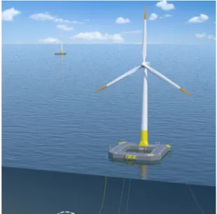
(44) Thèse de Haibo Zhang, Lille 1, 2017. 16. 1.2. OFFSHORE WIND TURBINE TECHNOLOGY. 1. The Hywind Spar-Buoys concept has a floating part similar to a monopile structure shown in Figure 1.3. A demo wind turbine has been in operation since 2009 in Norway [Niel 06]. 2. The Blue H Concept is based on the tension leg platform. A first prototype is placed off the coast of Italy in 2008 [Hube 08]. 3. The WindFloat Concept is developed by EDP and EDPR in Portugal. The floating foundation is semi-submersible and is stabilized by the use of “water entrapment plates” on the bottom of its three pillars. A demo project of 2 MW has been connected to the grid by the end of 2011 [Rodd 10]. 4. Ideol developed a French floating wind turbine demo project called Floatgen with a 2 MW wind turbine, constructed by Bouygues TP in 2017 [Berh 16], shown in Figure 1.4. This demo wind turbine is the first offshore wind turbine installed in France. Another demo project, EolMed, with 4 floating wind turbines rated at 6.2 MW is planned near the coast of Gruissan, France. Other examples of floating projects related to constructional design of wind turbines are described in the next subsection.. 1.2.2. Constructional design: horizontal vs vertical axis. Figure 1.5 shows the main components of a three-blade Horizontal Axis Wind Turbine (HAWT) compared to a φ-type Vertical Axis Wind Turbine (VAWT). It can be seen that the VAWT offers a symmetrical design with fewer components. However, current wind turbine market is dominated by HAWTs since its power conversion efficiency is superior to VAWTs, which has been proven by decades of research and development [Burt 11].. Figure 1.3 – Hywind 2.3 MW prototype deployed off the coast of Norway.. © 2017 Tous droits réservés.. Figure 1.4 – Floatgen floating project developed by IDEOL France.. lilliad.univ-lille.fr.
(45) Thèse de Haibo Zhang, Lille 1, 2017. CHAPTER 1. STATE OF THE ART OF OFFSHORE WIND POWER SYSTEMS. 17. Figure 1.5 – Main components of a HAWT and a φ-type VAWT [Hau 13]. The majority of the HAWTs possess three blades. Similar to many design considerations, the choice of the number of blades is a compromise between performance and cost. The optimal power coefficient of a three-blade wind turbine is 3% more than a two-blade wind turbine, while four-blade only offers 1% more than a three-blade. Moreover, a wind turbine having three blades is more dynamically stable. A two-blade solution offers a balanced mechanical design while it causes the so-called wobbling phenomenon [Hau 13], since, when the rotor is yawed to face the wind direction (to capture the maximum energy from the wind), two blades at the horizontal position vibrate leading to mechanical stress on the turbine shaft. The largest world’s commercial two-blade offshore wind turbine is the Mingyang SCD 6MW which has been deployed because it has less attack area to the wind so as to deal with the typhoon conditions that frequently occur in the East China Sea [Ming 15]. The deployment of HAWTs in the offshore wind turbine market is largely because it is based on proven and mature technologies for onshore wind turbines. However, the need for exploiting offshore wind energy in the deep sea has encouraged the use of floating foundations, described in previous section 1.2.1). Although the three-blade HAWTs are still used in many projects using floating foundations like the Hywind [Niel 06], Windfloat [Rodd 10], there are some works that have raised doubts on using HAWTs as the optimal design for floating applications [Suth 12][Borg 14]. Instead, they suggest that VAWTs, (of which many types has been developed based on the patent of the French engineer Georges Darrieus in 1922), become a promising replacement due to: 1. Fewer components: HAWTs must have a yaw control system which orients its blades to the wind direction before the blades can rotate. In contrast, the yaw system can be eliminated in a VAWT as its blades can be hit by the wind from any direction. Fewer components lead to cost reduction and a more reliable system.. © 2017 Tous droits réservés.. lilliad.univ-lille.fr.
Figure

+7
![Figure 1.29 – DC grid topology based on diode rectifier transmission proposed by Siemens [ Flye 15 ].](https://thumb-eu.123doks.com/thumbv2/123doknet/3649115.107648/69.892.118.798.105.349/figure-topology-based-diode-rectifier-transmission-proposed-siemens.webp)
Documents relatifs