HAL Id: hal-00798986
https://hal.archives-ouvertes.fr/hal-00798986
Submitted on 11 Mar 2013HAL is a multi-disciplinary open access archive for the deposit and dissemination of sci-entific research documents, whether they are pub-lished or not. The documents may come from teaching and research institutions in France or abroad, or from public or private research centers.
L’archive ouverte pluridisciplinaire HAL, est destinée au dépôt et à la diffusion de documents scientifiques de niveau recherche, publiés ou non, émanant des établissements d’enseignement et de recherche français ou étrangers, des laboratoires publics ou privés.
Analysis of weld-cracking and improvement of the
weld-repair process of superplastic forming tools
Arnaud Duchosal, Frédéric Deschaux-Beaume, Philippe Lours, Sergio Haro,
Gilles Fras
To cite this version:
Arnaud Duchosal, Frédéric Deschaux-Beaume, Philippe Lours, Sergio Haro, Gilles Fras. Analysis of weld-cracking and improvement of the weld-repair process of superplastic forming tools. Materials and Design, Elsevier, 2013, 46, pp.731-739. �10.1016/j.matdes.2012.11.003�. �hal-00798986�
Analysis of weld-cracking and improvement of the weld-repair process of superplastic
forming tools
A. Duchosala, F. Deschaux-Beaumea*, P. Loursb, S. Haroc, G. Frasa
a
Université de Montpellier II, Mechanical and Civil Engineering Laboratory, 30907 Nîmes,
France.
b
Université de Toulouse, Mines Albi, ICA (Institut Clément Ader), 81013 Albi cedex 09,
France.
c
Universidad Autónoma de Zacatecas, Unidad Academica de Ingeniería, 98000 Zacatecas, Mexico.
* Corresponding author. Tel: +33 466628586.
E-mail address: frederic.deschaux-beaume@univ-montp2.fr
Abstract
Superplastic forming (SPF) dies are generally made of using heat resistant cast steels, which
are very sensitive to weld cracking. In order to improve the weld-repair process of such dies
to prevent weld-cracking, the microstructure and the mechanical behaviour of a typical
heat-resistant cast steel was first studied, using isothermal low-cycle fatigue tests and in-situ tensile
tests. The welding behaviour of such steel was also investigated, using a shielded metal arc
welding (SMAW) process and welding conditions similar to those employed for weld repair
industrial dies. The comparison of the aspect of weld-cracking with the fracture mechanisms
observed at room temperature or during isothermal low-cycle fatigue tests suggests a similar
brittle failure mechanism, due to the presence of large interdendritic carbides in the cast steel.
The melting of the cast steel surface using a gas tungsten arc welding (GTAW) process
refining method with GTAW before welding has been successfully tested to weld-repair a
sample representative of SPF dies, and is recommended for subsequent repairs of such dies.
Key-words: Superplastic forming; Heat resistant cast steel; Weld-cracking; Weld-repair.
1. Introduction
Superplastic forming (SPF) consists in blowing metallic sheets to shape, using argon pressure,
within a die generally made of heat resistant cast steel [1]. Process is conducted at high
temperature, circa 900°C for TA6V alloy. The sheet, while inflated by argon, gradually takes
the shape dictated by the inner surface of the die. The elementary cycle of forming, including
heating, isothermal exposure and cooling, is repeated as many times as necessary to complete
the whole bench of parts to manufacture. Those cumulative cycles provoke the occurrence of
very severe thermomechanical stresses within the heat resistant cast steel dies [2]. This may
result to the initiation and propagation of fatigue cracks and ultimately to the early
catastrophic rupture of the die.
The increasing demand for manufacturing costs reduction requires developing appropriate and
reliable solutions for repairing, proper to extend the service life of the dies. Weld repairs are
generally performed using shielded metal arc welding (SMAW) technique, after a preliminary
machining to remove the damaged zone. However, processes used up to now do not show
sufficient guarantees for the users. Indeed, the welding of heat-resistant cast steels often
induces cracking, especially for massive components such as SPF dies [3-6]. This cracking,
generally located in the heat resistant cast steel close to the welded zone, is due to thermal
stresses induced by welding, and to subsequent plastic strain which can overstep the
Actually, there is no defined repair method for such dies, but some general rules are admitted.
A solution annealing treatment is recommended before welding to dissolve secondary
carbides and improve ductility [7]. However, this treatment is very costly for massive
components because the annealing temperature is above 1200 °C. A preheating of the dies
before welding is also required, to reduce thermal gradient during welding [8]. The maximal
preheating temperature is circa 400°C for operating without special equipment. The repairs
are more difficult for deep damaged zones, and cracks are very often formed after such
repairs. Then, a homogeneous welding with a heat resistant filler metal having a chemical
composition rather close to the base metal is generally considered not possible for repairing
deep cracking, and a welding with a “soft” metal is recommended. The mechanical strength of
such repairs is however low compared to base metal. The buttering technique, consisting to
deposit only a fine layer of a soft material on the surface of the filling zone on base material,
before to weld-repair with a more resistant material, is also effective to reduce cracking [7,8].
However, recent works have shown that weld repair samples obtained with buttering
technique have very low fatigue life time, so this repair process is not convenient for SPF dies
[9].
In order to better understand the cracking mechanism of heat resistant cast steels, and to
develop a method allowing weld-repair of SPF dies free of cracks, investigations were carried
out. This paper focuses on the analyses of the microstructure and the mechanical behaviour of
a heat resistant cast steel specially developed for SPF dies, and on the weld-cracking
mechanism, in order to improve the repairing process to prevent cracking.
2. Experimental details
The base material is a typical heat resistant cast austenitic stainless steel used for
manufacturing SPF tools, designated GX30NiCr3924 according to European standard.
The chemical composition of the cast steel (Aubert & Duval) is given on table 1. The high Ni
content conferees to the material a stabilized austenitic structure. The high C content, coupled
to the presence of Cr, Nb, V and Mo, induces the precipitation of hard carbides enhancing the
creep resistance at high temperature [10,11].
The samples were obtained by sand casting, and a stabilisation treatment is performed during
24 hours at 950°C.
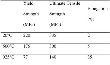
The mechanical properties of the base material are given in table 2. The room temperature
yield strength is rather low, but it only decreases slightly with temperature, remaining rather
high at 500°C. Note that the elongation to rupture is extremely low in the whole temperature
range, from room temperature to 500°C. This low ductility could explain the in-service
cracking of the tools during thermo-mechanical cycles, or the weld-cracking. Indeed, it is
generally assumed that a minimum elongation to rupture at room temperature of 4% is
required to prevent weld cracking [6].
2.2. Characterization method
In order to study the thermo-mechanical behaviour of the heat resistant cast steel, which has
an important impact on its behaviour during welding, the following program has been defined.
First, the microstructure of the cast steel has been analysed using scanning electron
microscopy (Philips XL30 SEM) observations, Energy Dispersive Spectrometry (EDS)
analysis, and Vickers micro-hardness measurements (500g). The goal of these analyses is to
identify some particular microstructure characteristics of the material responsible of its
Secondly, isothermal low-cycle fatigue tests are realized, at various temperatures from 500°C
to 920°C. A strain-controlled fatigue test was selected in order to simulate the mechanical
strain resulting from the thermal gradient due to multi-pass welding, each welding pass (up to
50 and more during weld-repair of SPF dies) generating a rapid thermal cycle. The strain
amplitudes were selected to be representative of typical strain cycles suffered by the material
during multipass welding, evaluated using numerical simulation [12,13]. Five strain
amplitudes, 0.4, 0.5, 0.6, 0.7 and 0.8%, resulting in a slight plastic strain at each cycle, were
chosen. The fatigue tests are carried out according to NF A03 403 French standard [14].
Details concerning fatigue tests are given in [9].
In order to better understand the mechanical behaviour of the heat resistant cast steel at the
microscopic scale, in-situ tensile tests are also carried out at room temperature using a
TS-300P tensile micromachine type, implemented in a Philips XL30 scanning electron
microscope. These tests especially allow to observe and analyze the cracking mechanism,
which is very particular for such heterogeneous material. Tensile samples with 2x2 mm2 cross
section and 30 mm length have been machined in a cast steel specimen. Before testing, the
samples were polished in order to observe their microstructure during the tensile test. The
tensile test is realized at constant displacement speed, and piloted by controlling the loading:
the sample is loaded in a continuous way up to 800 N (200MPa), and then in a intermittent
way, by increments of 40 or 50 N, with a stop between two increments to observe the
microstructure evolution.
2.3. Welding process
Weld-repair tests were carried out using samples preparation, welding technique and
parameters representative of industrial conditions. The size and geometry of the cast steel
terms of self-clamping effect and volume heat diffusion. On each sample, a V-groove (60°)
was machined before welding test to simulate a typical preparation prior to weld-repair a
cracked component (Figure 1a). Three samples geometries were prepared, with V-grooves
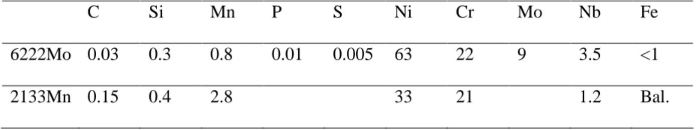
depth of 7, 12 and 20 mm respectively. For each sample geometry, two different filler metals
(Table 3) were used. The first one, designated 6222Mo (Bölher Thyssen), has a chemical
composition corresponding to a 625 nickel alloy, and is one of the most standard filler
materials used for welding nickel-base alloys or heat-resistant austenitic steels. The second
one, designated 2133Mn (Bölher Thyssen), has a composition rather close to the base metal,
and enable a quasi-homogeneous welding.
An automatic shielded metal arc welding process (SMAW), specially developed for the study,
has been used. During welding, the shielded electrode is horizontally translated at a constant
welding speed to fill in the V-groove, using a welding cantilever-beam. To ensure a constant
arc voltage, the electrode is also vertically translated while melted, using an electrically
controlled powered pay-off system.
The welding parameters, i.e. current, voltage and welding rate were the same for the 3
samples welded with the same filler metal, and are given in table 4. This corresponds to
typical welding parameters used for weld-repair industrial dies. Prior to welding, the base
metal samples have been systematically pre-heated uniformly at 400°C using heat resistances,
in order to reduce the thermal gradients and stresses during welding.
Only the depth of the welding zone, corresponding to a number of weld passes required to fill
in the groove, changes for the 3 types of samples. The first one, with a 7 mm deep
V-groove, is welded with 10 passes, the second one (12 mm deep V-groove) with 17 passes, and
the last one (20 mm deep V-groove) with 40 passes.
After welding, all the welded samples were cut, polished and analysed with optical
cracking behaviour of the cast steel during isothermal low-cycle fatigue tests, and at room
temperature at the microscopic scale, allow to discuss the weld-cracking mechanisms and to
improve the repair process.
3. Base material characterization
Before to weld-repairing, the base material has been extensively characterized in order to
better know its properties and especially its behaviour concerning cracking.
3.1. Microstructure
The alloy microstructure, revealed by scanning electron microscopy observations (Figure 2),
consists in a typical dendritic structure, with coarse primary arms (about 200 µm width), separated by carbide rich interdendritic zones.
Figures 3 b, c and d, show the result of an EDS analysis performed on the primary carbides
(interdendritic carbides) seen on the associated SEM micrograph (Figure 3a). They reveal the
presence of two types of carbides, namely chromium rich carbides (dark contrast in the
micrograph), and Nb rich carbides (bright contrast). These results are in accordance with
literature data concerning this kind of steel, that generally consider formed carbides are NbC
and Cr7C3 or Cr23C6 [15-21]. Borjali and al. also observed Cr3C2 type carbides [22,23],
probably due to a high cooling rate during casting, but these carbides change during high
temperature aging to M23C6 type carbides.
Nb carbides are less numerous and thinner than Cr carbides. The centre of the dendrites also
reveals the presence of a fine dispersion of secondary carbides, precipitated during the aging
treatment carried out after casting. This stabilization treatment promotes the carbide
solution. These secondary carbides are too small to be analysed by EDS, but literature
generally considers there are chromium carbides [1,11,15].
The micro-hardness of the steel, given in figure 4, shows a large discrepancy, due to the
heterogeneous microstructure. The austenitic matrix shows a rather low hardness (200 Hv),
whereas the large primary carbides have a very high hardness, up to 800 Hv.
3.2. Fracture behaviour
3.2.1. Fatigue tests results
For all fatigue tests achieved, the number of cycle to failure was rather low, ranged from 13 to
750 for strain amplitude varying from 0.8 to 0.4, whatever the temperature from 500 to
920°C. As the strain amplitude imposed during the fatigue test increases, the mean stress
amplitude also increases, and the number of cycle to failure decreases (Figure 5). These
results show that if the thermal strain induced by multipass welding during repair is high, then
fracture can occur for a very low number of welding passes.
Whatever the temperature, the fracture always shows a brittle aspect, with cleavage plans
(Figure 6). The scanning electron microscopy observations of the samples surface around the
fracture show secondary micro-cracks, across the carbides of the interdendritic zones (Figure
7). These results are a little beat different from that obtained by Kim et al., who observed also
a brittle fracture, but with transgranular propagation of cracks [24,25]. However, cracks
initiation was always located in the Cr-carbides precipitates, and the transgranular
propagation may be due to the less continuous morphology of the Cr-carbides formed in their
material, compared to the cast steel of the present study.
During in situ tensile tests, the first cracks appear brutally and simultaneously in several zones
from an axial loading of 1090 N (270 MPa) in the primary carbides (Figure 8a). The tensile
sample presents then a multi-cracked aspect, but cracks remain stable, and the tensile stress
continues to increase without braking the sample. From this stress level, after each increment,
some cracks propagate in a stable way, whereas new cracks form on the other primary
carbides, until the final break of the sample, corresponding to the unstable propagation of a
crack, which intervenes for a stress level of approximately 325 MPa (Figure 8f). On figure 8,
we can see that cracks form or propagate in a direction perpendicular to the loading direction
(horizontal direction).
If we compare the stress corresponding to the cracks initiation (270 MPa) to the yield stress of
the material (220 MPa), we notice that the cracks appear after a plastic strain. Carbides being
brittle, it is thus the austenitic matrix that deformed plastically.
We can observe that only chromium carbides (the darkest on the SEM micrographs) are
cracked, while niobium carbides, which appear in light colour on the SEM micrographs, are
never cracked (Figure 9).
The ductility and the higher toughness of the austenitic matrix is demonstrated by the
discontinuous aspect of the cracks. Indeed, the cracking occurs through primary chromium
carbides, and stops at the interface carbides-matrix (Figure 10). The crack can then start again
further, in another carbide situated in the continuation of the crack, and propagates in this one
until the next carbide-matrix interface is reached. The austenitic matrix acts then by an effect
of "pinching out" of cracks, which present an intermittent aspect in the plane. Figure 11 shows
well this phenomenon. On figure 11.a, the crack propagated through a primary carbide,
following a direction rather perpendicular to the loading direction, and stopped in the
interface with the matrix. Increasing load, the crack starts again in a carbide situated under the
again in the interface with the matrix (Figure 11b and c). Finally, the stress increasing again, a
bifurcation of the crack appears in the first cracked carbide, and the crack propagates in a
secondary thinner branch of this carbide (Figure 11d).
In some cases, before propagating through the other carbides, the cracks stopped at the
carbide-matrix interface are enlarged, and crack tip are blunted, because of the good ductility
of the matrix with regard to the carbides (Figure 12a). This blunting is the result of a very
local plastic deformation of the matrix at the crack tip. The slip planes corresponding to this
plastic strain are observed on figure 12b.
The similar aspect of cracks formed during in-situ tensile test and isothermal low-cycle
fatigue tests suggests a similar brittle failure mechanism at high (up to 920°C) and room
temperature. When the local stress reaches the cleavage stress of primary carbides, these are
breaking. Once cracked carbides, the crack tips, which stop in the matrix, undergo a blunting
by plastic strain of the austenite. The dislocation density in the nearby zone of the crack tips
then increases, creating piles at the interface with nearby carbides, which produce stress
concentrations and then the cracking by cleavage of these carbides, until the final break.
4. Weld-repair tests results
4.1. Analysis of weld-repaired samples
Six weld-repair tests were achieved according to the conditions defined in section 2.3. Cross
sections of the welded zone were then cut (Figure 1b) and polished in order to make
macrographic and micrographic observations.
The samples repaired with 10 passes are not cracked. In contrast, the samples
weld-repaired with 17 and 40 passes show numerous cracks in the base metal, close to the welding
gradients are higher, as evidenced in previous studies [12,13]. The cracks number and size
increase when the pass number increases from 17 to 40. These results are in accordance with
numerical results indicating that maximal stress in the base material increases with the depth
of the weld-repair, i.e. with the number of welding passes required to fill in the groove [13].
SEM micrographs reveal that cracks exclusively propagates in the carbide rich interdendritic
zones (Figure. 14a). At higher magnification, some smaller cracks are observed, with a
discontinuous aspect, and seem stopped by the austenitic matrix (Figure 14b). These last
investigations allow to observe that only primary chromium carbides are cracked, whereas the
Nb carbides (in light on figure 14b) are never cracked, as previously observed during in-situ
tensile tests. This could be due to a better tenacity of these phases, or to their morphology
thinner and more discontinuous than Cr carbides.
4.2. Discussion and improvement of weld-repair method
The classical weld-repair method presented in the last section, with a pre-heating at 400°C,
allows to repair small cracks, below circa 7 mm depth (10 passes). Above this depth, the
weld-repair creates new cracks due to the higher level of stress and strain induced by welding,
and to the low ductility of the base metal, resulting from its typical heterogeneous
microstructure containing large primary carbides with low toughness.
The cracks observed after welding always form in the cast steel close to the welding zone,
which is the region subjected to the highest stresses during the welding. The location of the
cracks, in the brittle primary carbides, and the similarity of crack aspect with those formed
at room temperature during in-situ tensile test or at high temperature during fatigue tests,
seem to suggest that a similar mechanism is responsible of the fracture in the different cases.
We can thus suppose that the material cracking during welding is the result of a brittle
induced by welding and of stress concentrations due to the strain incompatibilities between
the plastic matrix and the carbides.
The improvement of the weld-repair method to prevent cracking requires to act on the stress
or strain level suffered by the base material during welding, or on its cracking sensitivity.
The first way was explored in a previous paper, using a buttering technique to accommodate,
thanks to the deposit of a soft material layer on the surface of the V-groove, the thermal
strains induced by the successive welding passes [8]. This method allowed, under special
conditions, to prevent cracking during weld-repair of 20 mm deep V-grooves. However, the
fatigue life time of such repairs was very low [9], so other weld-repair techniques have to be
investigated for weld-repair SPF dies.
The second way was explored by Hebert [7], who propose to submit the cast steel to a
preliminary solution annealing treatment. This treatment allows the complete or partial
dissolution of the secondary carbides, and then improves the room temperature ductility of the
base material. However, it has been shown that this method was only efficient for aging
materials, specially when they suffered a coarsening of carbides [23], but not on as cast
materials, because the primary carbides, formed during the solidification of the alloy, are then
the main responsible of the very weak ductility of the cast steel. This is also the case for the
studied material, as observed on fatigue and in-situ tensile tests. The annealing treatment also
can have a detrimental effect, by promoting the cracking of coarse carbides, due to thermal
stresses induced during the cooling after heat-treatment [23].
The elementary mechanisms responsible for the cast steel cracking are strongly conditioned to
the very particular microstructure of the material, constituted by a ductile austenitic matrix,
surrounded by a narrow interdendritic zone, composed of a mixture of austenite and eutectic
carbides. These last ones are from two different types: chromium carbides, the most numerous
interdenditric zones, that form a continuous network around the austenite, constitute the zones
of weak toughness, sensitive to cracking. The improvement of the cracking resistance then
requires the modification of the microstructure in these zones, to increase their toughness.
The cleavage stress of a given compound depends on its physical characteristics, but also of
its size. Indeed, the more the grain size of a crystal or the size of an inclusion is weak, the
more the cleavage stress is raised. This could explain why only chromium carbides undergo
cracking, while niobium carbides, thinner, are not sensitive to the phenomenon, because
their cleavage stress is more raised. The large size of the primary carbides is then partially
responsible of the poor toughness of the steel. This is for this reason that some authors
recently try to promote the formation of thinner and more discontinuous primary carbides
during casting of heat-resistant austenitic stainless steels by the addition of a few percent of
some elements like titanium [22,26].
The largest primary carbides, formed during the solidification process of the cast steel, can't
be dissolved in the solid solution, even at high temperature. The only way to change their
size or morphology is to re-melt the cast steel, which can be costly for an industrial use.
Fortunatly, only the part of the material suffering the highest stresses and strains, located in
the immediate vicinity of the welding zone, has to change microstructure to avoid cracking.
It can be achieved by the melting of the surface of the heat resistant cast steel using a gas
tungsten arc welding (GTAW) process, without filler material. This solution was
experimented, to verify the effect of such melting to refine the microstructure, especially the
size of the primary carbides. Figure 15 shows that the mean width of primary carbides
changes from about 10 µm in the row material to about 2 µm after GTAW re-melting. This refining treatment has been applied on the surface of the V-groove of a sample, before
to weld-repair with SMAW process, in order to refine the microstructure in the zone
successfully tested for weld-repair in a 20 mm deep V-groove (Figure 16), and is
recommended for subsequent deep weld-repairs.
5. Conclusion
A microstructural and mechanical characterisation of a heat resistant cast steel has been
achieved in order to try to improve the weld-repair process of superplastic forming (SPF) dies.
This type of material has a typical microstructure consisting of an austenitic matrix
surrounded by a narrow interdendritic zone rich in brittle primary carbides, which conferee to
the material a very low ductility up to 500°C.
In situ tensile tests allowed to observe the failure mechanism at room temperature of the cast
steel, which consist in a multi-cracking of the primary carbide “network” from a given
loading, and a propagation of cracks across the nearby carbides, up to the final fracture. The
failure during isothermal low-cycle fatigue tests seems to happen according to similar
mechanism, up to 920°C.
Finally, welding tests were carried out using similar conditions than weld-repair conditions
for industrial SPF dies. The analysis of the welded samples revealed a cracking of the base
metal around the fusion zone, and the crack aspect suggests a similar brittle failure
mechanism that observed at room temperature under tensile loading, or during low-cycle
isothermal fatigue.
The weld-cracking is supposed to be caused by the thermal stresses created around the weld
during the repair process, due to the presence of large brittle carbides in the microstructure,
which can not accommodate the stresses. It is then supposed that a refining of the carbides,
for instance by re-melting with an electric arc the surface to be weld-repair, could improve the
the surface produced a great refining of the microstructure of the base material, and allowed
to weld-repair successfully the dies, without cracking.
References
[1] Montagnon J, Moraux JY, Hocquette A. Application of thermo-calc to the developments
of new heat-resistant alloy casting for specifics SPF-DB tooling. In : Cépadues-Editions,
editor. Proceedings of the 3rd European Conference on Super Plastic Forming, Albi, France;
2004, p. 117-124.
[2] Branza T, Martinier A, Duchosal A, Deschaux-Beaume F, Bernhart G, Lours P. Fatigue
damage and weld repair of heat resistant cast steel SPF dies. In : Cépadues-Editions, editor.
Proceedings of the 3rd European Conference on Super Plastic Forming, Albi, France; 2004, p.
133-138.
[3] Haro S, Lopez D, Velasco A, Viramontes R. Microstructural factors that determine the
weldability of a high Cr-high Si HK 40 alloy. Mater Chem Phys 2000; 66: 90-96.
[4] Haro S, Colas R, Velasco A, Lopez D. Study of weldability of a Cr-Si modify heat
resistant alloy. Mater Chem Phys 2002; 776: 831-835.
[5] Haro S, Ramirez C, Mendoza E, Rodriguez J, Colas R. Microstructural analysis of
heat-resistant welded pipes. Mater Charact 2003; 51: 21-27.
[6] Colwell RL, Hoffman JJ. Weld cracking in modified heat resistant castings, a
microstructural investigation. In : NACE international, editor. Proceedings of the NACE
International Annual Conference Corrosion 98; 1998, paper 423.
[7] Ebert HW. Fabrication of HK-40 in the Field. Weld J 1976; 11: 939-945.
[8] Branza T, Deschaux-Beaume F, Sierra G, Lours P. Study and prevention of cracking
[9] Branza T, Deschaux-Beaume F, Velay V, Lours P. A microstructural and low-cycle
fatigue investigation of weld-repaired heat-resistant cast steels. J Mater Process Technol
2009; 209: 944–953.
[10] Wu XQ, Jing HM, Zheng YG, Yao ZM, Ke W, Hu ZQ. The eutectic carbides and creep
ruptures strength of 25Cr20Ni heat-resistant steel tubes centrifugally cast with different
solidification conditions. Mater Sci Eng A 2000; 293: 252-260.
[11] De Almeida LH, Ribeiro AF, Le May I. Microstructural characterization of modified 25
Cr-35Ni centrifugally cast steel furnaces tubes. Mater Charact 2003; 49: 219-229.
[12] Branza T, Duchosal A, Fras G, Deschaux-Beaume F, Lours P. Experimental and
numerical investigation of the weld repair of superplastic forming dies. J Mater Process
Technol 2004; 155-156: 1673-1680.
[13] Duchosal A, Deschaux-Beaume F, Bordreuil C, Fras G, Lours P. Method for predicting
risk of cracking during weld repair of heat resistant cast steels. Sci Technol Weld Join 2008;
13-2: 126-135.
[14] NF A03-403. Metal products - Low-cycle fatigue test. 1990-12-01.
[15] Rodriguez J, Haro S, Velasco A, Colas R. A metallographic study of aging in a cast
heat-resisting alloy. Mater Charact 2000; 45: 25-32.
[16] Piekarski B. Effect of Nb and Ti additions on microstructure, and identification of
precipitates in stabilized Ni–Cr cast austenitic steels. Mater Charact 2001; 47: 181-6.
[17] Kenik EA, Maziasz PJ, Swindeman RW, Cervenka J, May D. Structure and phase
stability in a cast modified-HP austenite after long term ageing. Scripta Mater 2003; 49:
117-22.
[18] Voicu R, Andrieu E, Poquillon D, Furtado J, Lacaze J. Microstructure evolution of
[19] Dehmolaei R, Shamanian M, Kermanpur A. Microstructural characterization of
dissimilar welds between alloy 800 and HP heat-resistant steel. Mater Charact 2008; 59:
1447-54.
[20] Laigo J, Christien F, Le Gall R, Tancret F, Furtado J. SEM, EDS, EPMA-WDS and
EBSD characterization of carbides in HP type heat resistant alloys. Mater Charact 2008; 59:
1580-1586.
[21] Liu J, Jiao D, Luo C. Microstructural evolution in austenitic heat-resistant cast steel
35Cr25Ni12NNbRE during long-term service. Mater Sc Engineer 2010; A527: 2772-2779.
[22] Borjali S, Allahkaram SR, Khosravi H. Effects of working temperature and carbon
diffusion on the microstructure of high pressure heat-resistant stainless steel tubes used in
pyrolysis furnaces during service condition. Mater Des 2012; 34: 65–73.
[23] Allahkaram SR, Borjali S, Khosravi H. Investigation of weldability and property changes
of high pressure heat-resistant cast stainless steel tubes used in pyrolysis furnaces after a
five-year service. Mater Des 2012; 33: 476–484.
[24] Kim YJ, Jang H, Oh YJ. High temperature low cycle fatigue properties of a HF30-type
cast austenitic stainless steel. Mater Sc Engineer 2009; A526: 244–249.
[25] Kim YJ, Jang H. High temperature fatigue resistance of an ACI HH50-type cast
austenitic stainless steel. Mater Sc and Engineer 2010; A527: 5415–5420.
[26] Piekarski B. The influence of Nb, Ti, and Si additions on the liquidus and solidus
temperatures and primary microstructure refinement in 0.3C-30Ni-18Cr cast steel. Mater
Figures captions
Figure 1: Geometry (a) of the samples for weld-repair tests, and (b) preparation of cross
sections for microstructural analysis
Figure 2 : Microstructure of the heat-resistant cast austenitic steel (SEM)
Figure 3 : Microstructure (a) and EDS analyses of matrix (b), dark contrast precipitates (c)
and bright contrast precipitates (d)
Figure 4: Micro hardness profile of the heat resistant cast austenitic stainless steel
Figure 5: Number of cycles to failure versus main stress amplitude during isothermal fatigue
tests
Figure 6: Fracture pattern of a sample fractured during low cycle fatigue test at 750°C
Figure 7: Secondary cracks in a fatigue sample fractured at 500°C
Figure 8: Multi-cracked aspect of in-situ tensile sample and crack propagation up to the fracture,
for a tensile stress of 272 MPa (a), 282 MPa (b), 300 MPa (c), 310 MPa (d), 320 MPa (e) and 325
MPa (f)
Figure 9: Micrograph of in-situ tensile sample showing cracked Cr carbides (in grey) and
Figure 10: Discontinuous aspect of the crack propagation through the primary chromium
carbides
Figure 11: Crack propagation through primary carbides, and “pinching” of the crack by the
austenitic matrix, after a tensile stress of 255 MPa (a), 272 MPa (b), 300 MPa (c), 325 MPa
(d)
Figure 12: Blunting by plastic strain (a) and slip planes (b) around a crack tip
Figure 13 : Cross section of weld-repaired sample showing the fusion zone and the cracks in
the base material
Figure 14: (a) Crack propagation across the interdendritic zone after welding in the base
material close to the fusion zone, and (b) cracking of the Cr primary carbides (in grey)
Figure 15 : Comparison of the size of primary carbides in the heat resistant cast steel (a) in the
initial state, and (b) after a GTAW melting
Figure 16: Weld-repair of heat-resistant cast steel after a preliminary GTAW re-melting of the
Table 1: Chemical composition of the heat resistant cast austenitic stainless steel
GX30NiCr3924
Fe C Cr Ni Mn Si P S Mo W Nb V
wt % bal 0.313 24.40 39.2 1.11 1.45 <0.001 0.0011 <0.020 <0.002 0.328 0.038
Table 2 : Mechanical properties of the heat resistant cast austenitic stainless steel
GX30NiCr3924 Yield Strength (MPa) Ultimate Tensile Strength (MPa) Elongation (%) 20°C 220 335 2 500°C 175 300 5 925°C 77 140 35
Table 3: Chemical composition of the filler metals, in wt%
C Si Mn P S Ni Cr Mo Nb Fe
6222Mo 0.03 0.3 0.8 0.01 0.005 63 22 9 3.5 <1
2133Mn 0.15 0.4 2.8 33 21 1.2 Bal.
Table 4: Welding parameters
Filler material Welding speed (mm/s) Welding current (A) Voltage (V) 2133Mn 2.7 63 24 6222Mo 2.7 63 25