HAL Id: tel-01511290
https://tel.archives-ouvertes.fr/tel-01511290
Submitted on 20 Apr 2017HAL is a multi-disciplinary open access archive for the deposit and dissemination of sci-entific research documents, whether they are pub-lished or not. The documents may come from teaching and research institutions in France or abroad, or from public or private research centers.
L’archive ouverte pluridisciplinaire HAL, est destinée au dépôt et à la diffusion de documents scientifiques de niveau recherche, publiés ou non, émanant des établissements d’enseignement et de recherche français ou étrangers, des laboratoires publics ou privés.
Actuators for Position Synchronization
Jian Fu
To cite this version:
Jian Fu. Incremental Virtual Prototyping of Electromechanical Actuators for Position Synchro-nization. Mechanical engineering [physics.class-ph]. INSA de Toulouse, 2016. English. �NNT : 2016ISAT0008�. �tel-01511290�
THÈSE
En vue de l'obtention du
DOCTORAT DE L’UNIVERSITÉ DE TOULOUSE
Délivré par :
Institut National des Sciences Appliquées de Toulouse (INSA de Toulouse)
Discipline ou spécialité :
Génie Mécanique, Mécanique des Matérieux
Présentée et soutenue par : Jian FU
Le mercredi 6 Juillet 2016 Titre :
Prototypage Virtuel Incrémental des Actionneurs Electromécanique pour la Synchronisation en Position
JURY
Geneviève DAUPHIN-TANGUY, Professeur, Ecole Centrale de Lille, Rapporteur Jesús FELEZ, Professeur, Universidad Politécnica de Madrid, Rapporteur
Jean-Charles MARE, Professeur, INSA de Toulouse, Examinateur Ion HAZYUK, Maître de Conférences, INSA deToulouse, Examinateur
Yongling FU, Professeur, Beihang University, Invité
Ecole doctorale :
Mécanique, Energétique, Génie civil, Procédés (MEGEP)
Unité de recherche :
Institut Clément Ader (ICA, CNRS UMR 5312)
Directeur(s) de Thèse :
Université fédérale de Toulouse Midi-Pyrénées
Institut National des Sciences Applique e de Toulouse
Institut Cle ment Ader (CNRS UMR 5312)
Incremental Virtual Prototyping of Electromechanical
Actuators for Position Synchronization
Doctoral Thesis
Prepared by: Jian FU
Supervisor: Prof. Jean-Charles MARE
Reviewers: Prof. Genevie ve DAUPHIN-TANGUY
Prof. Jesu s FELEZ
Examiner:
Inviter:
Mcf. Ion HAZYUK
Prof. Yongling FU
Toulouse
July 2016
Abstract
In the aerospace field, the concepts based on extended use of electricity in “More Electric Aircraft” (MEA) and even “All Electric Aircraft” (AEA), electromechanical actuators (EMAs) are increasingly being implemented in place of conventional hydraulic servo actuators (HSAs). When EMAs are used for safety-critical actuation applications like flight controls, some specific issues related to thermal balance, reflected inertia, parasitic motion due to compliance, response to failure (jamming and free-run) and synchronization of EMAs driving independent loads cannot be ignored. The simulation-aided design process can efficiently support the assessment and validation of the concepts fixing these issues. For that, virtual prototypes of EMAs at system-level have to be developed in a structured way that meets the engineers’ needs. Unfortunately, the physical effects governing the EMAs behavior are multidisciplinary, coupled and highly nonlinear. Although numerous multi-domain and system-level simulation packages are now available in the market of simulation software, the modelling process and the engineers’ needs are rarely addressed as a whole because of lack of scientific approaches for model-based architecting, multi-purpose incremental modelling and model implementation for efficient numerical simulation. In this thesis, the virtual prototyping of EMAs is addressed using the Bond-Graph formalism. New approaches are proposed to enable incremental modelling of EMAs that provides models supporting control design, energy consumption and thermal analysis, calculation of reaction forces, power network pollution simulation, prediction of response to faults and influence of temperature. The case of preliminary design of EMAs position synchronization is used to highlight the interests and advantages of the proposed process and models of EMAs.
Keywords: Bond-Graph, More Electric Aircraft, Power-by-Wire, EMA, Energy Losses, Response to
Acknowledgements
First of all, I am grateful to China Scholarship Council (CSC) for providing me with 40 months of financial grant and support for my doctoral studies in France.
I would like to express my sincere gratitude to my supervisor, Mr. Jean-Charles MARE, at INSA-Toulouse, Institut Cle ment Ader (ICA). I am indebted to him for his guidance and help during my PhD thesis. His rigorous research attitude and good work ethics will have an everlasting impact on my life.
I would also like to specially thank Mr. FU Yongling, in Beihang University, for his instructive advice during my M.S and first year of PhD in Beihang. I am deeply grateful for his recommendation, which gave me the opportunity to pursue my PhD degree in France.
I would also like to express my thanks to Mr. Ion HAZYUK, in INSA-Toulouse, ICA, for his discussion and contribution towards my thesis. I would like to thank Mr. Nicolas LAURIEN and Mr. Ste phane ORIEUX, for their assistance and suggestions during the experimental tests in my PhD.
I am also deeply indebted to all my Chinese and international friends in the laboratory of ICA, for their help, encouragement and friendship during my Ph.D studies.
Finally, the last words are for my family. In the most difficult time, during the mid of my Ph.D study, my father was no more. I would especially like to thank my mother for her continued support and encouragement during these tough moments of my overseas study, and she is indeed a great mother. I dedicate this thesis to my father in heaven, thank you very much!
Contents
Nomenclature
... IIntroduction
... 1Chapter 1 State of the Art
... 71.1 Flight Control Actuators ... 7
1.2 Safety Cirtical Requirments and Position Synchronization ... 13
1.3 Virtual Prototyping Methodology ... 21
1.4 Performance Requirements ... 26
1.5 Conclution of Chapter 1 ... 27
References ... 27
Chapter 2 Individual EMA Controller Design
... 312.1 Individual EMA System Description ... 31
2.2 Linear Virtual Prototype ... 35
2.3 Power Limitation and Saturation Effects ... 42
2.4 Motor Current Loop Effects ... 45
2.5 Imperfections due to Mechanical Compliances ... 53
2.6 Force Feedback Compensation for Position Control ... 62
2.7 Conclusion of Chapter 2 ... 71
References ... 72
Chapter 3 Power Drive Electronics and Motor
... 733.1 Physical Effects in Power Drive Electronics (PDE) ... 73
3.2 Physical Effects at Electric Motor (EM) ... 85
3.3 Incremental Virtual Prototyping ... 95
3.4 Numerical Simulation and Analysis ... 104
3.5 Conclusion of Chapter 3 ... 111
4.1 Power Screw Mechanism ... 116
4.2 1-DoF Integrated Model ... 119
4.3 2-DoF Decomposition Model ... 131
4.4 Model Implementation ... 148
4.5 Numerical Simulation and Analysis ... 156
4.5 Conclusion of Chapter 4 ... 167
References ... 168
Chapter 5 Test Bench and Preliminary Study of Position
Synchronization
... 1715.1 Description of the Test Bench ... 171
5.2 Preliminary Study of Position Synchronization ... 181
5.3 Validation of Overall Twin-Parallel EMAs Virtual Prototype ... 191
5.4 Conclusion of Chapter 5 ... 201
References ... 202
Conclusion
... 205List of Publications
... 209Appendix
... 211 Appendix A BLDC vs.PMSM Used for EMAs ... 211Appendix B SKF Bearing Loss Model ... 217
Doctoral Thesis – Jian FU I
Nomenclature
Parameters
0 Reference Temperature [°C]
Conduction Loss Model Parameter [-]
m Temperature Dependency of Materiel Magnet [1/°C]
r Temperature Dependency of Resistance [1/°C]
Steinmetz Constant [-]
Cogging Factor [-]
b Constant Coefficient of Bearing Friction [-]
m Magnetic Permeability [H/m]
hp High Pass Filter Time Constant [s]
lp Low Pass Filter Time Constant [s]
i Motor Current PI controller Time Constant [s]
ω̂n Desired Nature Frequency [rad/s]
ξ̂ Desired Damping Factor [-]
a Conduction Voltage Drop Model Parameter [V]
As Effective Area of Core [m2]
asw Switching Loss Curve Fitting Constant [J]
b Conduction Voltage Drop Model Parameter [V]
bsw Switching Loss Curve Fitting Constant [-]
Bm Peak Value of the Magnetic Flux Density [T]
c Conduction Voltage Drop Model Parameter [-]
CN Motor Rated Torque [Nm]
de Damping Factor in Compliance [N/m/s]
dm Bearing Mean Diameter [m]
Eroff Reference Turn-off Energy Losses of IGBT/Diode [J]
Eron Reference Turn-on Energy Losses of IGBT/Diode [J]
Fcl Coulomb Friction Force of Friction Loss Model [N]
Fst Stribeck Friction Force [N]
Fjam Jamming Force in Advance Friction Model [N]
fhp High Pass Filter Frequency [Hz]
flp Low Pass Filter Frequency [Hz]
fp Resonance Frequency [Hz]
fsw Switching Frequency [Hz]
fv Viscous Friction Coefficient [Nm/rad/s]
Ir Rated Current for IGBT/Diode [A]
Iref Switch Current at Reference Condition [A]
JL Load Inertial [kgm2]
Jm Motor Rotor Inertia [kgm2]
Km Motor Torque Constant [Nm/A] or [V/rad/s]]
II Doctoral Thesis – Jian FU
ke Pure Spring Stiffness of Nut-screw [N/m]
ked Eddy Current Constant [-]
keq Equivalent Stiffness of EMA [N/m]
kn Nut-screw Stiffness [N/m]
ks Structural Stiffness [N/m]
kt Transmission Stiffness Between EMA rod and Load [N/m]
Kt0 Motor Torque Constant at Reference Temperature [Nm/A]
Kf Force Feedback Controller Proportional Gain [Nm/N]
Khp High Pass Filter Gain [-]
khy Hysteresis Constant [-]
Klp Low Pass Filter Gain [-]
Kii Motor Current Loop Integral Gain [V/A/s]
Kip Motor Current Loop Proportional Gain [V/A]
Kp Position Controller Proportional Gain [rad/s/m]
Kp Speed Synchronization Controller Proportional Gain [Nm/rad/s] Kpr Position Synchronization Controller Proportional Gain [Nm/m]
Kir Position Synchronization Controller Integral Gain [Nm/ms]
Kdr Position Synchronization Controller Derivative Gain [Nm/m/s]
Kv Velocity Controller Proportional Gain [Nm/rad/s]
l Lever Arm Length [m]
lm Effective Magnetic Path Length [m]
Lm Motor Windings Inductance [H]
Mm Mass Reflected at Load by Motor Rotor Inertia [kg]
Ms Equivalent Surface Mass [kg]
Mt Mass of the EMA Rod [kg]
N Number of Turns in the Coil of Motor [-]
np Motor Number of Pole Pairs [-]
p Lead of Roller Screw [m]
Rm Motor Windings Resistance []
Ron0 On State Resistance for IGBT/Diode at Reference Temperature []
Ron On State Resistance for IGBT/Diode []
Rs0 Motor wingding resistance at Reference Temperature []
𝑡̂𝑠 Desired Response Time [s]
U0 Static Forward Voltage Drop by IGBG/Diode [V]
Uref Switch Voltage at Reference Condition [V]
Us Electric Power Supply [V]
x0 Backlash or equivalent preload parameter in Compliance Model [m]
x*0 Backlash or equivalent preload parameter by wear [m]
xw Wear Parameter [m]
Variables
Temperature [°C]
1 Actual Operating Temperature [°C]
Duty Cycle for Control Motor Power Drive [-]
Motor Velocity Saturation Ratio [-]
c Torque Saturation Ratio [-]
Doctoral Thesis – Jian FU III
p Static Error Under Step Demand [m]
v Tracking Error Under Ramp Demand [m]
d Static Disturbance Error [m]
L Loads Synchronization Error [m]
L Rods Synchronization Error [m]
Degree [°]
m Motor Rotor Angle Position [°]
s Surface Deflection Angle [°]
c Current Loop Time Constant [s]
e Motor Electric Time Constant [s]
Rotation Velocity [rad/s]
b Support Bearing Rotational Velocity [rad/s]
c Current Loop Break Frequency [rad/s]
i Motor Current Loop Nature Frequency [rad/s]
m Motor Rotor Velocity [rad/s]
rmax Maximum Velocity Reference From Position Controller [rad/s]
n Nature Frequency [rad/s]
nr Relative Rotational Velocity Between Nut and Bearings [rad/s] r Velocity Reference From Position Controller [rad/s]
Damping Factor [-]
i Current Loop Damping Factor [-]
Magnetic Flux [Wb]
B Magnetic Flux Density [T]
C Torque [Nm]
C* Torque Reference Demand for Electric Motor [Nm]
Cad Aerodynamic Torque on Surface [Nm]
Caxl Torque Loss Due to Axial Load [Nm]
Cb0 Load Independent Bearing Friction Moment [Nm]
Cb1 Load dependent Bearing Friction Moment [Nm]
Cbl Bearing Friction Torque [Nm]
Ccg Motor Compliance Torque (Cogging Torque) [Nm]
Cd Motor Dissipative Torque [Nm]
Cdrag Frictional Moment of Lubrication Loss of Bearing [Nm]
Ced Equivalent Eddy Current Torque Losses [Nm]
Cem Motor Electromagnetic Torque [Nm]
Cfm Motor Friction Torque [Nm]
Chy Equivalent Hysteresis Torque Loss [Nm]
Cj Inertia Torque of MPT [Nm]
Cm Torque of Motor Shaft [Nm]
Coil Torque Loss Due to Oil of Bearing [Nm]
Cr Motor Torque Reference From Velocity Controller [Nm]
Crad Torque Loss Due to Radial Load of Bearing [Nm]
Crmax Maximum Torque Reference From Velocity Controller [Nm]
Crr Rolling Frictional Moment of Bearing Loss [Nm]
Cs Position Synchronization Controller Compensate Torque [Nm]
Cseal Frictional Moment of Seals [Nm]
Csl Sliding Frictional Moment of Bearing Loss [Nm]
IV Doctoral Thesis – Jian FU
Esw Switching Energy Losses of IGBT/Diode [J]
Edoff Switching Turn-off Energy Losses of Diode [J]
Edon Switching Turn-on Energy Losses of Diode [J]
Etoff Switching Turn-off Energy Losses of IGBT [J]
Eton Switching Turn-on Energy Losses of IGBT [J]
fi Current Loop Frequency [Hz]
fs Undamped Natural Frequency [Hz]
F Force [N]
Fc Compliance Contact Force [N]
Fd Damping Force of Compliance [N]
Fe Elastic Force of Compliance [N]
Fex External Force Disturbance [N]
Ff Friction Force in Mechanical Power Transmission [N]
F*f Friction Force with Jamming [N]
FL EMA Load Force [N]
FLA EMA_A Load Disturbance Force [N]
FLB EMA_B Load Disturbance Force [N]
Fr Force Output form EMA Rod [N]
Fs EMA Output Force [N]
H Magnetic Field Strength [A/m]
id Operating Current for IGBT/Diode [A]
Id Average Current Flowing Through the IGBT/Diode [A]
Iin Switch Input Current [A]
Im Electric Motor Current [A]
Imw Motor Wingdings Current [A]
Is Electric Current Supply [A]
Isw Equivalent Current Leak by Switching in IGBT/Diode [A]
Jn Nut-screw inertia [kgm2]
Kt Motor Torque Constant During Operation [Nm]
Pbl Bearing Power Losses [W]
Pco Copper Loss [W]
Pcd Conduction Power Losses of IGBT/Diode [W]
Pd Power Loss by Compliance Damping [W]
Ped Eddy Current Loss [W]
Pf Friction Power Loss [W]
Phy Hysteresis Constant [W]
Psw Switching Power Losses [W]
Rmw Motor wingding resistance []
Ron1 On State Resistance for IGBT/Diode at Operating Temperature []
Ṡ Entropy Flow [J/K/s]
td IGBT/Diode Conduction Time [s]
ts Response Time [s]
tcs Motor Current Loop Response Time [s]
Uco Voltage Drop Due to Copper Loss [V]
Ud Voltage Drop by IGBT/Diode [V]
Um Electric Motor Voltage [V]
vb Support Bearing Translational Velocity [m/s]
Doctoral Thesis – Jian FU V
Vd Diode Voltage [V]
Ve Linear Velocity of EMA Rod [m/s]
Vex External Linear Velocity [m/s]
vr Relative Linear Velocity in Nut-screw [m/s]
vs EMA Output Linear Velocity [m/s]
vsr Relative Translational Velocity Between Screw and Bearings [m/s]
x Linear Displacement [m]
Xc Position Command [m]
Xca EMA_A Position Command [m]
Xcb EMA_B Position Command [m]
Xe EMA Rod Displacement [m]
Xr EMA Reference Control Setpoint [m]
xr Relative Deformation by Compliance [m]
Xs Surface Equivalent Linear Displacement [m]
Xsa EMA_A Surface Equivalent Linear Displacement [m]
Xsb EMA_B Surface Equivalent Linear Displacement [m]
Xt EMA Rod Displacement [m]
Xta EMA_A Rod Displacement [m]
Xtb EMA_B Rod Displacement [m]
Abbreviation
A/C Aircraft Control AEA All Electric Aircraft bemf Back Electromotive Force BLDC Brushless Direct Current Motor CCS Cross-Coupled Synchronization DC Direct Current
DoF Degree of Freedom
EBHA Electro Backup Hydrostatic Actuator EHA Electro-Hydrostatic Actuator EM Electric Motor
EMA Electromechanical Actuator FBW Fly By Wire
FBWL Fly By Wireless FBL Fly By Light FC Flight Control
FCC Flight Control Computer FOC Field-Oriented Control HIL Hardware In-the-Loop HMA Hydro-Mechanical Actuator HSA Hydraulic Servo Actuator HMU Health Minoring and Usage IGBT Insulated Gate Bipolar Transistor
ITAE Integral of Time-weighted Absolute Error LVDT Linear Variable Displacement Transducer MBSE Model-Based System Engineering
VI Doctoral Thesis – Jian FU
MIMO Multiple Input Multiple Output
MOSFET Metal-Oxide-Semiconductor Field-Effect Transistor MPT Mechanical Power Transmission
NS Nut-Screw
PbW Power-by-Wire PCU Power Control Unit PDE Power Drive Electronics
PID Proportional–Integral–Derivative PMSM Permanent Magnet Synchronous Motor PWM Pulse Width Modulation
RC Resistance-Capacitance SIL Software In-the-Loop
THS Trimmable Horizontal Stabiliser TRAS Thrust Reverser Actuation System XPC Real Time Control Computer
Doctoral Thesis – Jian FU 1
Introduction
In recent years, the increase in fuel costs, the environmental footprints and the emergence of new competitors have driven the aerospace industry to introduce step changes towards greener, safer and cheaper air transport [1]. The concepts based on extended use of electricity in “More Electric Aircraft” (MEA) and even “All Electric Aircraft” (AEA) have logically defined the technological shift towards “greening” aviation operations, using the electric power networks to replace conventional hydraulic networks [2][3]. Currently, numerous research activities strive to widen the use of electrical power networks for electrically supplied power users (Power-by-Wire or PbW) in replacement of the conventional hydraulic, pneumatic and mechanical power networks [4]. At the same time, PbW actuators have become sufficiently mature to be introduced in the latest commercial programmes:
-Electro-hydrostatic actuators (EHAs) as backup actuators for primary and secondary flight controls in Airbus A380 / A400M / A350,
-Electromechanical actuators (EMAs) as frontline actuators for a few secondary flight controls and for landing gear braking in Boeing B787.
Although they remove the central hydraulic power distribution, EHAs still use hydraulics locally to keep the major advantages of conventional actuators regarding secondary functions (back-driving, overload protection, damping) and response to failure (easy hydraulic declutch and extremely low risk of jamming). EMAs, however, remove both central and local hydraulic circuits by transmitting the motor power to the load through mechanical reducers (e.g. gearbox, nut-screw, etc.). Nevertheless, EMAs are not yet sufficiently mature to replace conventional hydraulic servo-actuators (HSA) in normal mode for safety-critical functions such as primary flight controls. Several technical challenges still need to be taken up: weight and size constraints for integration, voltage spikes and current transients affecting the pollution and stability of the electrical network, heat rejection for actuator thermal balance,
2 Doctoral Thesis – Jian FU
reduced reflected inertia for dynamic performance, increased service life and fault tolerance or resistance (e.g. for jamming or free-run) for safety [5][6]. In particular, introducing more or all electrical actuation by using EMAs raises new challenges:
a) Heat Rejection
It is well known that the temperature of motor windings and power electronics is a key element affecting service life and reliability. Thus, thermal balance is an important issue for PbW actuation. In HSAs, the heat generated by energy losses is taken away by the fluid returning to the reservoir. Conversely, the heat in PbW actuators has to be rejected locally to the surroundings or to a heatsink. The simulation of lumped-parameter models can provide a detailed view of the temperature and heat flow fields [7][8]. Unfortunately, these methods are too time-consuming for modelling and simulation at system level. In addition, they cannot be used in the early design phases because they are too detailed and they require numerous parameters that are not yet known in these phases. The heat generated in EMAs comes from a multiplicity of sources: electronic (switching and conduction losses), electrical (copper losses), magnetic (iron losses) and mechanical (friction losses). It is very interesting to accurately quantify this heat during a reference flight cycle because it determines the operating temperature of the actuator’s components.
b) Response to Failure
Safety-critical functions like primary flight controls have to show extremely low failure rates (e.g. 10-9 per flight hour). This is achieved through redundancy by installing multiple channels. However, each channel must be fail-safe to enable the remaining channels to operate correctly. In EMAs, this requirement introduces another challenge, when jamming and free-run faults of mechanical components are considered. In HSAs, a fail-safe response to failure (free, damped or frozen) is easily obtained at low mass and low cost by resorting to bypass valves, restrictors, piloted check valves or isolation valves. Unfortunately, it is no longer possible to transpose the needs from the hydraulic domain to EMAs where clutches, brakes, dampers and torque limiters may be required. Virtual prototyping at system-level therefore becomes very interesting, not only to support conceptual design but also to verify
Doctoral Thesis – Jian FU 3
the control and reconfiguration strategies.
c) Pollution of Electrical Supply
The control of power of electrical machines (e.g. actuator motor) is based on high frequency on/off switching (e.g. 8 to 16 kHz) of power semi-conductors through pulse width modulation (PWM). Although power is controlled with very low energy losses, it generates high transients in the electrical supply bus and can affect the stability of the electrical network. Moreover, regenerative currents need to be managed properly under aiding-load conditions. This is another reason why model-based systems engineering (MBSE) of PbW actuators calls for more realistic models.
d) Motivation of the Research Work
However, with the constant efforts of aviation, on recently developed commercial airplanes and future aircraft program will certainly rely on more increasing use of electrical power, and EMAs will be more involved on the next generation aircraft. The first concept is that EMA will work together with HSA or EHA as a hybrid redundancy structure to drive single surface for primary flight control application, such as aileron. This redundant structure has been investigated with consideration of force equalization in much academic research works [9-11].
This thesis has been conducted at Laboratory Institut Clement Ader, Institut National des Sciences Applique es de Toulouse (INSA-Toulouse). It can be seen and the logical continuation of former defended Ph.D studies that were related to the modelling, simulation and control of electrically powered actuators for aerospace applications:
-WANG Lijian, “Force Equalization for Active/Active Redundant Actuation System Involving Servo-hydraulic and Electro-mechanical Technologies”, INSA-Toulouse, France Thesis, 2012.
-QI Haitao, “Research on Actuation System Architecture of More Electric Aircraft and Electro-Hydrostatic Actuator (EHA)”, Beihang University, Codirected by INSA-Toulouse and Beihang University, China Thesis, 2010.
4 Doctoral Thesis – Jian FU
-KARAM Wissam, “Investigation into the electromechanical actuator when used for high performance force control”, INSA-Toulouse, France Thesis, 2007.
-NFONGUEM Gustave, “Contribution to the development of a more electrical actuator – inverse modelling mechanical components specific to an aerospace application”, INSA-Toulouse, France Thesis, 2006.
On its side, the present research work addresses the case where 2 EMAs drive separately 2 independent loads (flight control surfaces) that shall be position-synchronized at any time. This typically corresponds to secondary flight control, such as flaps, slats, or to thrust reverser applications. The conventional position synchronization strategy is centralized via a mechanical shaft system. It is heavy, bulky and not flexible. Individual loads offer new opportunities for distributed actuation that requires synchronization control strategies.
According to the above mentioned needs and challenges, the present thesis intends to propose incremental models of EMAs and their components to support the various engineering needs appearing during the development and integration of actuation systems. The typical application that will be addressed is presented on Fig. 1.
FC Surface 2 FC
Surface 1 EMA1 EMA2 “Electrical” Synchronization Thrust reverser doors Flaps or slats Thrust reverser doors Flaps or slats
Fig. 1 “Electrical” synchronization structure of EMAs for thesis study
All above considerations highlight the interest of developing high fidelity virtual prototype with a transverse view of the physical domains involved in EMAs for position synchronization. A model-based and simulation-driven approach can unquestionably provide engineers with efficient means to address all these critical issues as a whole. In particular, it will facilitate and accelerate the assessment of innovative architectures and concepts [12][13], and also their technological embodiments. This thesis will make wide use of the Bond-Graph methodology for graphical and qualitative modelling. Bond-Graph modelling [14][15] explicitly displays the
Doctoral Thesis – Jian FU 5
multidisciplinary energy transfers, and the structure and the calculation scheme for simulation. Incidentally, it facilitates the design of a model structure that enables incremental (or even decremental) modelling. The thesis is organized as follows:
In chapter 1, state of the art of actuation for flight control is firstly introduced and the objectives, requirements and methodology of virtual prototyping of EMAs for position synchronization are presented. In chapter 2, the individual EMA controller with position/velocity/force loops is designed on the basis of the linear approach. The saturation (torque and velocity), motor current loop and compliances effects are considered. In chapter 3, the incremental virtual prototypes of power drive electronics (PDE) and electric motor (EM) of EMA are built respectively, with resort to Bond-Graph formalism. Multi-level of models are implemented and tested in the LMS-AMESim, and the numerical simulation and results are analyzed. In chapter 4, the virtual prototyping of mechanical power transmission (MPT) of EMA is also addressed with an incremental approach, the physical effects are progressively introduced. The one degree of freedom (1-DoF) and two degrees of freedom (2-DoF) models are proposed, implemented and tested in LMS-AMESim. In chapter 5, the test bench configuration is presented for next experimental study. The preliminary position synchronization of EMAs is addressed, a proportional–integral–derivative cross-coupled synchronization (PID-CCS) controller is proposed. Then, the proposed models (linear or advanced) of EMAs are integrated and simulated to illustrate how they can support the assessment of the PID-CCS control strategy. In the end, the general conclusions summarizes the main proposals and achievements of this research work, and gives perspectives for further development of system-level virtual prototyping and position synchronizing.
Reference
[1] X. Roboam, B. Sareni, and A. D. Andrade, "More electricity in the air: Toward optimized electrical networks embedded in more-electrical aircraft," Industrial Electronics Magazine, IEEE, vol. 6, pp. 6-17, 2012.
[2] J. A. Rosero, J. A. Ortega, E. Aldabas, and L. Romeral, "Moving towards a more electric aircraft,"
6 Doctoral Thesis – Jian FU
[3] S. L. Botten, C. R. Whitley, and A. D. King, "Flight control actuation technology for next-generation all-electric aircraft," Technology Review Journal, vol. 8, pp. 55-68, 2000.
[4] I. Chakraborty, D. N. Mavris, M. Emeneth, and A. Schneegans, "A methodology for vehicle and mission level comparison of More Electric Aircraft subsystem solutions: Application to the flight control actuation system," Proceedings of the Institution of Mechanical Engineers, Part G: Journal
of Aerospace Engineering, vol. 229, pp. 1088-1102, 2015.
[5] X. Yu and Y. Zhang, "Design of passive fault-tolerant flight controller against actuator failures,"
Chinese Journal of Aeronautics, vol. 28, pp. 180-190, 2// 2015.
[6] M. Todeschi, "Airbus-EMAs for flight controls actuation system-perspectives," presented at the International Conference on Recent Advances in Aerospace Actuation Systems and Components (R3ASC), Toulouse, France, 2010.
[7] W. Takebayashi and Y. Hara, "Thermal design tool for EHA," in International Conference on Recent
Advances in Aerospace Actuation Systems and Components (R3ASC), Toulouse, France, 2004, pp.
15-20.
[8] E. Fauge re, J.-C. Mare , C. Changenet, F. Ville, and D. Delloue, "Coupling mechanical and thermal lumped parameters models for the preliminary design of power transmissions driven by thermal issues," in 28th International Congress on Aerospace Sciences (ICAS), Brisbane, Australia, 2012, pp. 3690-3700.
[9] L. Wang and J.-C. Mare , "A force equalization controller for active/active redundant actuation system involving servo-hydraulic and electro-mechanical technologies," Proceedings of the
Institution of Mechanical Engineers, Part G: Journal of Aerospace Engineering, vol. 228, pp.
1768-1787, 2014.
[10] W. Karam and J.-C. Mare , "Force control of a roller-screw electromechanical actuator for dynamic loading of aerospace actuators," in International Conference on Fluid Power and Motion Control, 2008.
[11] W. Ur Rehman, S. Wang, X. Wang, L. Fan, and K. A. Shah, "Motion synchronization in a dual redundant HA/EHA system by using a hybrid integrated intelligent control design," Chinese
Journal of Aeronautics, 2016.
[12] I. Chakraborty and D. N. Mavris, "Integrated Assessment of Aircraft and Novel Subsystem Architectures in Early Design," presented at the 54th AIAA Aerospace Sciences Meeting (SciTech), San Diego, California, USA, 2016.
[13] J. Liscoue t, J.-C. Mare , and M. Budinger, "An integrated methodology for the preliminary design of highly reliable electromechanical actuators: Search for architecture solutions," Aerospace Science
and Technology, vol. 22, pp. 9-18, 2012.
[14] G. Dauphin-Tanguy, A. Rahmani, and C. Sueur, "Bond graph aided design of controlled systems,"
Simulation Practice and Theory, vol. 7, pp. 493-513, 12/15/ 1999.
[15] W. Borutzky, "Bond graph modelling and simulation of multidisciplinary systems – An introduction," Simulation Modelling Practice and Theory, vol. 17, pp. 3-21, 1// 2009.
Doctoral Thesis – Jian FU 7
Chapter 1
State of the Art
The thesis focuses on virtual prototyping of electromechanical actuators for position synchronization in aerospace application. The complex, numerous and cross-linked parasitic effects of electromechanical actuator are incrementally modeled with the support of Bond-Graph formalism. The state of the art of aerospace actuation will be firstly introduced. The innovations and developments of electrically powered actuators, especially electromechanical actuators, for recent aircraft even for next generation of more electric aircraft application are presented. For safety critical actuation applications like flight control, the safety issues and reliability requirements are of particular importance. For this reason, the redundancy configurations will be presented. The following part will address the common active/active mode of operation for actuators with its main issue for electromechanical actuators: the position synchronization. Then, the incremental modelling approach, considering with priority the engineering needs and the physical effects, will be introduced as it has been used extensively in the present work.
1.1 Flight Control Actuators
The new generation of aircraft will use almost exclusively electric power distribution networks. For this reason, the actuators should evolve to take advantage of this development, in terms of performance, weight and maintenance.
1.1.1 Power Distribution
In aeronautics, as in all types of aircrafts, we can define the primary and secondary power systems [1]. The primary power is to ensure the movement of the aircrafts (propulsion, traction, lift, etc.). The secondary power relates to other power systems (air conditioning, flight controls, landing gears, fuel, anti/de-ice, etc).
8 Doctoral Thesis – Jian FU
In today’s commercial aircraft, primary power is created by the main engines. It comes from the combustion of aviation fuel in a gas turbine that produces reaction forces (jet aircrafts) or a mechanical rotational power (turbo-propellers). For example, in the Airbus A330, the propulsion power is typically 40 MW [2].
The secondary power is essentially derived from primary energy. It is used to supply the aircraft no-propulsive systems. On a conventional commercial airplane, there are generally four types of energy networks: pneumatic, mechanical, hydraulic and electric. In Airbus A330, as shown in Tab. 1-1, the total "non-propulsive" power is about 1.74 MW [2].
Table 1-1 Various secondary powers in an Airbus A330
Power types Application systems
Pneumatic : 1,200kW air conditioning, cabin pressurization, anti/de-icing, etc. Mechanical : 100kW secondary power generators (hydraulic pumps and electric
generators), etc.
Hydraulic : 240kW flight controls, landing gear, brakes, thrust reverse, etc. Electric : 200kW avionics, de-icing, lighting, cabin system, etc.
1.1.2 Flight Control of Civil Aircraft
Yaw control Roll control Pitch control Slats Spoilers Ailerons Flaps Trimmable Horizontal Stabilizer (THS) Rudder Elevators Primary flight control
Secondary flight control
Fig.1-1 Flight control of an Airbus A330 [3]
In an aircraft, the flight control system aims at acting on the trajectory of the aircraft (primary) and on the aerodynamic configuration (secondary) by moving control surfaces
Doctoral Thesis – Jian FU 9
from the commands given by the pilot (or autopilot) [4]. Flight Control system includes all the components between the cockpit control units and control surfaces. Figure 1-1 shows the flight control architecture of an Airbus A330 [3].
Primary Flight Control: The primary flight controls are used to control the evolution of the aircraft around its reference axis during the flight [4]: the rudder or rudder for yaw control, the ailerons and spoilers for roll control, and the elevators and the trimmable horizontal stabilizer (THS) for pitch control.
Second Flight Control: The secondary flight controls allow changing the aerodynamic configuration of the aircraft during landing and takeoff phases: Flaps and slats for lifting, spoilers for the trail, airbrakes.
1.1.3 Actuators Technology Innovations
Actuator servo control is used to position a flight control surface to follow a setpoint. This is a key element in the flight control of an aircraft. As illustrated in Fig. 1-2, it is historically hydraulic powered by an external centralized hydraulic system or via an electromechanical pump associated with a local hydraulic power generation.
Surface Airfoil
Air Load & Disturbance
Actuator Servo Control Commands
Flight Control Surface Demanded Angle θ*
Surface response θ
Fig.1-2 Schematic of actuator servo-control
Actuator used for aerospace applications first appeared in earlier 1940. Until now, it has gone through many times of innovation and updating. The development history and future tendency are summarized in Tab. 1-2.
10 Doctoral Thesis – Jian FU
Table 1-2 Summary of actuator technology development [3]
Decade Actuator Signaling Powering
~-1940s Null Mechanical Cables Human Mechanical
1950s Hydro-Mechanical Actuator (HMA) Mechanical Cables Human Mechanical + Hydraulic Assist
1960s (with stability augmentation) HMA Mechanical Cables Hydraulic
1980s Hydraulic Servo Actuator (HSA) Electric Wires (Fly-By-Wire) Hydraulic
2000s HSA & Electrically powered Actuator (Electro-hydrostatic actuator(EHA),
Electromechanical actuator (EMA)) Electric Wires (FBW)
Electric + Hydraulic (Power-By-Wire)
2020s?
EHA & EMA Electric Wires (FBW) Electric (PBW)
EHA & EMA Optical Fiber Cables (Fly-By-Light, FBL) Electric (PBW)
2030s?
EMA Optical Fiber Cables (Fly-By-Light, FBL) Electric (PBW)
EMA Wireless Protocol (Fly-By-Wireless, FBWL) Electric (PBW)
As the rapid growth of air traffic market in recent years, man-made CO2 emissions into the atmosphere increased largely by civil aviation. The aircraft industry has to face both economic and environmental issues [5]. Currently, an interim and attractive solution is towards “More Electric Aircraft” (MEA) using more electric power technological advancements for non-propulsive systems of aircrafts. On this basis, today’s aircraft actuation systems prefer power-by-wire (PBW) and have centered on novel approaches to design and develop electrically powered actuators.
Currently, aircraft manufacturers are still in an intermediate step. The latest generation of commercial aircraft such as the Airbus A380 or A350 is an example since they have a mixed the type of power supply to the flight controls. By suppressing one hydraulic circuit over three in favor of electrical networks; it was possible to significantly reduce the weight of the aircraft (5%, for the A380) [6]. This approach has resulted in a new generation of PBW actuators of EHAs or electro backup hydrostatic (EBHA) types.
Doctoral Thesis – Jian FU 11
Across the Atlantic, the latest project from Boeing, the 787, is also intended to be the "most electric" aircraft, as said by the MOOG Company that provides 21 flight control surface actuators, all hydraulically power excepted 4 EMAs for spoilers [7].
Undoubtedly, the next airliners will see an increase in the use of electrical power. The Airbus A380/A350 and Boeing 787 are paving the way to the future single-aisle, medium-haul. Three reasons explain this tendency [8]:
(1) First, the permanent objective is to reduce the overall weight of the aircraft - thus its fuel consumption. In fact, the use of electrical instead of hydraulic systems provides flexibility in terms of design, integration and power management.
(2) Secondly, this same design flexibility offers significant potential for personalization and adaptation of systems to the customer needs.
(3) Finally, maintenance promises to be more efficient because the electrical circuits can be tested and diagnosed more easily. The maintenance actions are expected to be reduced.
However, there is no question in near future of replacing the hydraulic networks and generators by electric wire and electric motors: the announced rule of electric power is a revolution that engages the power architecture of the aircraft to achieve substantial gains. Yet the introduction of major technological breakthroughs in commercial aviation is a process that lasts for many years [4].
Nowadays, beyond the well-known HSAs, the new uses have three different concepts of PBW actuators for flight controls: EHAs, EBHAs and EMAs [9].
(a) Hydraulic Servo Actuator (HSA)
HSAs are powered by hydraulic power and controlled by a servo valve, displayed in Fig. 1-3 (a). The power transfer is metered by introduction of hydraulic variable resistors between the constant pressure hydraulic source of and cylinder. When the HSA is not active, a mode select valve forces the actuator to operate in a damping mode.
12 Doctoral Thesis – Jian FU Gear Servovalve Manifold Accumulator Jack A330/340 Aileron (a) HSA Jack PDE M
(d) EMA: Direct drive type
Jack PDE Manifold Accumulateur Pomp M PDE Electric Motor Electric power Servovalve Manifold Jack (c) EBHA Pomp M PDE Hydraulic power (b) EHA A380 Aileron A380 Rudder Jack Boeing 787 Spoiler Mark: Exlar
Delete some hydraulic constraints
(d) EMA: Gear drive type Servovalve replaced by a pomp
plus an electric motor
EHA a s ba ck-up mode Sevrovalve as normal function mode Accumulator Electric Motor Electric power Electric power Electric Motor integrated Hydraulic power Electric power Electric Motor
Fig.1-3 Different actuators for flight controls
(b) Electro-hydrostatic Actuator (EHA)
In the last decades, numbers of investigations explored EHAs technologies and achieved deep understanding studies. Unlike the HSAs, for control flight surfaces, EHAs use internally a hydraulic power generation that removes the need for a centralized hydraulic power distribution. Thus, EHAs have their own fluid reservoir. A high-speed electric motor drives at variable speed a fixed displacement hydraulic pump, the speed of the motor controlling functionally the load velocity, as the servovalve current does in HSAs, as per Fig. 1-3 (b). The EHAs are used on elevators and ailerons for the A380 and A 350 as backup actuators [10]. In this figure, the electronic control box is integrated in the actuator package.
(c) Electro Backup Hydrostatic Actuator (EBHA)
The EBHA appeared for reasons of safety: it has a compact structure but provides an effective dissimilar redundancy solution regarding the sources of power. As shown in Fig. 1-3 (c), an EBHA implements a hybrid power architecture and combines the EHA structure for backup
Doctoral Thesis – Jian FU 13
and an HAS structure for normal mode. The EHA and HAS are sharing a same jack and the working mode is changed by a selector valve. In recent aerospace applications, the rudder and some spoilers for the A380 are driven (among others) by EBHAs.
(d) Electromechanical Actuator (EMA)
EMAs compared to EHAs, eliminate all the hydraulic circuits, as show the successful applications in Boeing 787 for a few secondary flight controls. The use of EMAs is pursued not only because of its clean energy but also for fuel consumption reduction and maintenance cost reduction for aircraft actuation systems. Hence, EMAs technologies are crucial for the ultimate goal to the achievement of the All Electric Aircraft.
Currently, two types of linear EMAs are regarded for flight control applications: geared and direct drive. As shown in Fig. 1-3 (d), when the nut screw is directly driven by the electric motor, the EMA is so-called direct drive. When an intermediate reduced in introduced, the EMA becomes a geared EMA. Whatever the type of EMAs, the electric energy is converted into mechanical one by a rotary electric motor which transfers the mechanic power to the control surface through an optional gearbox and a nut-screw mechanism. Direct drive EMAs cancel the gear reduction and offer a high potential for geometrical integration of the nut-screw reducer and the electric motor. Although the required motor torque is higher than in a geared EMA, direct-drive EMAs seem to be lighter and more compact.
1.2 Safety-Critical Requirements and Position Synchronization
The safety issues a very demanding for the design and operation of commercial aircrafts. When it comes to perform critical functions, such as primary flight controls, the reliability aspects become more preponderant. Therefore, one most important issue of reliability requirements is to ensure the actuation system provides the right level of failure rate and the right response to failure [11]. For example, especially in EMAs, the most feared events come generally from the jamming susceptibility of mechanical power transmissions, the short circuit in electric motor windings and power drive electronics.
14 Doctoral Thesis – Jian FU
1.2.1 Redundancy Configuration
In order to meet these safety issues and reliability requirements for today’s aircraft design, the flight control actuation systems have to be redundant. The dual redundant actuation configuration is considered here and summarized in three common arrangements [12], as shown in Fig. 1-4, the internal redundancy, the actuator redundancy and the surface redundancy. Actuator 1 Actuator 2 Actuator 1 Actuator 1 Actuator 2 Actuator 2 Surface Surface Surface Surface
(a) Internal redundancy (b) Actuator redundancy (c) Surface redundancy
Fig.1-4 Examples of redundancy configuration to control surface
The dfferent redundant configurations impact the design objectives to reduce the probability of “loss of control” of the driven surface:
(a) Internal redundancy
A single actuator jack integrates multiple power paths to drive a single actuator arm. This redundant configuration is applied on fighters or helicopters. However, it is unable to completely avoid the presence of common failure points and just tolerates a failure in the power path.
(b) Actuator redundancy
That is the most common and simplest apparent solution for fault tolerance. A single moving surface is driven by two or multiple actuators. When actuators operate in active/damping mode, only one actuator is in charge of the positioning function while the other operates as a damper. The roles are reversed in case of failure of the active channel. While in active/active mode, both actuators equally drive the load, so “force fighting” may occurr and produce additional stress or energy consumption. For primary flight control systems of today’s commercial aircraft (e.g. both A380 and B787), no single surface is driven by a single actuator. The actuators are involved into dissimilar redundant (e.g. HSA/EHA) or similar redundant
Doctoral Thesis – Jian FU 15
(e.g. HSA/HSA) [13]. (c) Surface redundancy
When multiple surfaces availably perform a same control mission, for example, surface of spoilers or slats are used for reducing lift as well as increasing drag. Therefore, each moving surface can employ a single actuator. In case of failure, the actuator can be locked in failed position or return to a defined position. And the remaining surfaces are normally operated.
Today, advanced technologies are developed in electrical and electronics domains, which provide a wider use of PbW actuators. Because of maturity and response to failure, PbW does not enable removing all conventional actuators (e.g. HSA). But nowadays in aerospace industry for new generation aircraft design, the electrically supplied actuators, especially EMAs, are being more and more considered.
From a more academic viewpoint, using EMA in the area of aerospace application considering the safety-critical functions, there has been much research focused on internal redundancy, Fig. 1-4 (a). The fault-tolerant and fault bypassing methods have been proposed in EMA electric drives and power paths design [13]. Also in our laboratory, Institute Cle ment Ader (ICA), from 2001 we began to take interest in the EMA technology, then in 2006, Dr. G.NFONGUEM did thesis defense with a contribution to the development of more electric actuators for THS [14] . Then Dr. W. KARAM and Dr. L.J WANG focused on the development of a hybrid redundant configuration of an HSA and an EMA actuation test bench, corresponding to the Fig. 1-4 (b) arrangement. Dynamic force generators were designed with resort to different modeling levels of EMA mechanical components [15]. In addition, force equalization strategies were studied when HSA and EMA operate in active/active mode to drive a single load [3].
The present thesis focuses on EMA technologies for safety-critical functions, according to the surface redundancy arrangement, Fig. 1-4 (c). The main progress concerns the development of advanced system-level virtual prototypes of EMA for position synchronization of independent loads. Due to the different natural dynamics and external loads, the two
16 Doctoral Thesis – Jian FU
independent loads tend to have a different position, which is not acceptable when applied to symmetrical surfaces control for spoilers, slats or even thrust reversers doors (or transcowls). Therefore, one of the main interests of this thesis is to enable addressing virtually the response to failure, in order to verify that the safety requirements are met for position synchronized EMAs.
1.2.2 Position Synchronization in Aerospace Application
At present for aerospace application, in position synchronization is the key technology and is well applied for some different functions.
(a) Application to Thrust Reverser Actuation System (TRAS)
The thrust reverser actuation system is used in many turbine engines for aircraft to assist in reducing the horizontal speed of the aircraft after touch-down, reducing wear on the brakes and enabling shorter landing distance [16]. This action allows sending the air flow generated by the reactor forward and develops a forward force during the landing phase. Nowadays, some different thrust reverser types can be found in aircrafts, as shown in Fig. 1-5.
a) Bucket type b) Clamshell door type c) Translating cowl type
(Source: Fokker70, KLM) (Source: Airbus A320, Easyjet) (Source: Airbus A380, AirFrance)
Fig.1-5 Different thrust reverser types
Taking an example of Airbus A340-600, the thrust reverser is supplied with constant pressure hydraulic power from onboard hydraulic network. For each engine, the function of thrust reverser is achieved by translating two panels (translating cowl or transwcol type) that produce the reversal of the air flow (a right panel and left panel of the engine). Each panel is driven by three actuators and bonded to the nacelle engine so as to provide a motorized
Doctoral Thesis – Jian FU 17
sliding connection. Furthermore, in order to reduce the risk of jamming, the three jacks are mechanically synchronized and connected by using two flexible shafts, as shown in Fig. 1-6. The mechanical position synchronization helps to both halves of the thrust reverser and lock the system in flight.
Fig.1-6 Mechanical synchronization in thrust reverser by using flexible shaft [17]
(b) Application to Secondary Flight Control Actuation System
The flaps and slats are the most common devices in high lift actuation system for aircraft secondary flight control. They must always be extended and retracted identically on both left and right wings to maintain the symmetry of flight, as displayed in Fig. 1-7.
Fig.1-7 Boeing 737 wings drive system [18]
Figure 1-8 shows a conventional architecture of a flap actuation system, due to the permanent coupling, the entire flap or slat system movements must be position-synchronized and usually
18 Doctoral Thesis – Jian FU
centrally-controlled by a power control unit (PCU), which is usually redundant (using centralized hydraulic and/or electric power). The power is transmitted to drive a mechanical shaft, which transmits motor to the loads through several gear boxes (BGB, KGB), rotary hinges and actuators. For security consideration, wing tip brakes (WTB) are used to perform the functions of position holding for shaft system or gear box failures. Meanwhile, several torque limiting devices (STL) are needed with the function of protection against the excessive loads of the wing or the actuator in case of jamming faults. In addition, for health minoring and usage (HMU) consideration, several sensors for system control, cockpit display and failure detection (FPPU, IPPU, APPUs) are available.
Fig.1-8 Architecture of a conventional flap drive system of Airbus A330/A 340 [19]
(c) Application to Tiltrotor Aircraft Conversion Actuation System
Position synchronization applications also can be found in today’s most recent tiltrotor aircrafts, such as V22 Osprey, XV-15 and AW609/BA609. They are also be called the vectored-thrust aircraft that takes off and lands vertically like a helicopter but converts to airplane mode while in flight [20], seen Fig. 1-9.
(a).Helicopter mode (b). Conversion mode (c). Airplane mode
Doctoral Thesis – Jian FU 19
For position synchronization, V22 Osprey, XV-15 and AW609/BA609 have the similar functions, which have a pylon conversion actuation system for angular positioning and synchronisong their two engine nacelles to switch from one mode to another (helicopter /airplane) [20]. In order to ensure high reliability and safety requirements, the conversion actuators usually have multi-redundant architectures. For example, as the principle of the AW609/BA609 conversion actuator is shown in Fig. 1-10.
Fig.1-10 Functional schematic of AW609/BA 609 conversion system [20]
Each conversion actuator is supplied with different and independent power networks. In addition, the conversion actuator consists of a two-stage, telescopic ball-screw that is driven by a planetary gear differential with two inputs: a primary hydraulic drive unit or a backup unit. The synchronizing motion of the wing on each side of the aircraft is mechanically linked via an elastic cross shaft located in the leading edge of the wing. The position synchronization is also monitored electronically to ensure synchronous operation even if in case of failure in the power path [20, 21].
1.2.3 Interests of Future “Electrical” Position Synchronization
In early very small aircraft system and today’s some industry process system, the position synchronization was performed hydraulically (e.g. using flow dividers) or by dedicated
20 Doctoral Thesis – Jian FU
strategies that elaborate the control signal of each actuator servovalve [22]. The example of secondary flight controls, have shown how synchronization is achieved mecanically. However, although the mechanical synchronization is mature, the potential failure of mechanical shaft or actuator may cause the entire flap or slat high lift system to jam and the overall function to be lost. So the mechanical synchronization is not a very flexible configuration and has a large number of components, is heavy and requires significant installation space. For next generation aircraft, “electrical” position synchronization has a great interest, in particular with distributed control of PbW actuators, such as EMAs.
Power Drive Electronics Control Electronics Power Drive Electronics Control Electronics EMAs Synchronization Electric Power Network
Signal bus
Fig.1-11 Concept of “electrical” synchronization of EMAs for thrust reverser actuation system
Figure 1-11 shows a concept of “electrical” synchronization of EMAs for thrust reverser actuation system in future more electric aircraft [23]. The thrust reverser includes two doors individually driven by two electromechanical actuators (EMAs). The control law for position synchronization of the two doors of the TRAS is implemented in the control electronic units that pilot the power drive electronics (PDE) associated with each EMA motor. The electronic control units of the actuators can also exchange data between each other via an electrical connection. The control units are in charge of generating the movement sequence of the two doors, to regulate the position and to synchronize the doors’ position in any case. This electrically solution is more flexible and facilitates the realization of the position synchronization function.
Doctoral Thesis – Jian FU 21
In addition, “electrical” position synchronization also can be developed in the field of secondary flight control actuation system by introducing a concept of “distributed actuation system”. Different from the previously presented conventional high lift system, each surfaces, flap or slat, is driven by an independent EMA. This concept potentially enables different positions to be ordered for each actuator in order to improve the quality of flight. Figure 1-12 gives an example of application coming from the research project DEAWS (Distributed, Electrically Actuated Wing System) [24].
Fig.1-12 Concept of electrically synchronization of EMAs for flaps and slats [24]
All surfaces of left wing and right wing are mechanically independent and their position synchronization is fully electric [25]. The other project NEFS (New track integrated Electrical Flap Drive System) [26] is based on the similar configuration. It main objective is to firstly simplify the synchronization control while optimizing the power architecture. The second objective is to develop a distributed electrical flap drive system that is completely integrated into the flap support structure.
This thesis aims at contributing to the assessment of electrical position synchronization by mean of realistic simulation. Because of safety critical requirements, the position synchronization methodology needs to be validated and verified in the presence of faults. Therefore, a full model of electrically position synchronization of EMAs for independent load control is a key step and need to be firstly addressed. It will facilitate the next step that will be addressed, that deals with the real validation with a generic test bench.
1.3 Virtual Prototyping Methodology
22 Doctoral Thesis – Jian FU
future aircraft. Fig. 1-13 shows the architecture of two EMAs driving independent surfaces under independent dynamic load. Each actuator is individually controlled and position synchronization will be added between the two EMA controllers. Considering the importance of response to faults for a safety critical application, it is of prior importance to develop virtual and real test means with progressive transition between simulated and real worlds through hardware in-the-loop (HIL) and software in-the-loop (SIL). Therefore, in the frame of this thesis, it is firstly needed to develop a virtual prototype of these two EMAs to virtually evaluate the position synchronization strategy on the full model before implementing the real controller and running real tests.
Sensors Motor Surface 1 Aerodynamic Load 1 Command signal 1 Airframe EMA 1 Sensors Motor Surface 2 Command signal 2 Airframe EMA 2
Electric Power Supply
Position/force feedback 1 Position/force feedback 2 Autopilot Signal bus EMA controller 1 EMA controller 2 Pilot Power Drive Electronics 1 1 Monitoring informations Monitoring informations Synchronization Aerodynamic Load 2 V el oc it y fe ed ba ck 1
Electric Power Supply
i w Power Drive Electronics 2 2 i w V el oc it y fe ed ba ck 2
Fig.1-13 Architecture of electrical synchronization of EMAs for thesis study
The present application involves two identical EMAs. Therefore, virtual prototyping of individual EMA is firstly needed, which can support system-level design, development, integration and monitoring. However, there is a huge requirement for realistic models, which include the architecting (functional, conceptual then technological), sizing and specification of sub-systems (preliminary then detailed), and their integration, verification and validation (virtual then real) [27]. All these considerations motivated the work in this thesis, which has
Doctoral Thesis – Jian FU 23
the main objective of developing and implementing models that reproduce with realism the multi-domain cross-link disciplines. The models shall meet the system-level engineering needs and the associated constraints. In particular generic models shall be developed with progressive complexity and with same interfaces in order to make then easily replaceable.
1.3.1 Cross-linked Multi-domain Disciplines
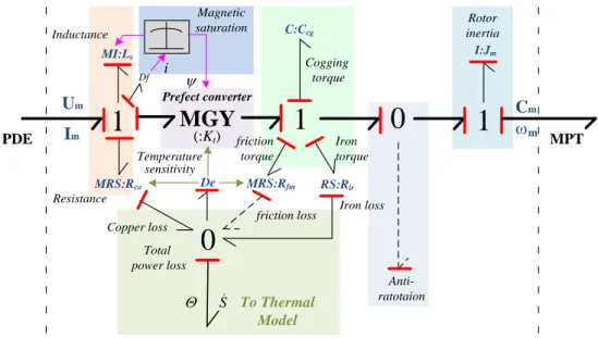
Thermal balance Power drive electronic (PDE) Conduction, Switching losses Mechanical transmission (MT) Friction loss Copper loss Electric motor (EM) Iron losses (eddy., hyst.) Ṡe Qe Qf Ṡf Ṡi Ṡc Qc Qi Mechanic Magnetic Electrical Ḣ: entropy flow Q: temperature
Fig.1-14 Multi-domain coupling of EMA system
Virtual prototyping of EMA system requires multidisciplinary approaches for preliminary power sizing and performance evaluation. The thermal effect is a key effect that drives sizing, performance and lifespan. Unlike a HSA, the heat generated by energy losses in EMAs has to be dissipated (or stored) at the actuator level, excepted in very specific applications where the actuator can be cooled by a dedicated liquid circuit. These energy losses come from switching in transistors (commutation losses), resistance of wires/windings and power electronics (copper and conduction losses), eddy currents and magnetic hysteresis (iron losses) in the motor, and friction losses between moving bodies. Most of these losses govern the thermal balance of the EMA as the heat the produce must be dissipated toward the local environment. Moreover, the sensitivity of energy losses to actual temperature may produce snowball effects that cannot be ignored. All this effects induce a strong multidisciplinary coupling among physical domains, as depicted by Fig. 1-14. The virtual prototype to be developed shall reproduce with realism the physical effects and their coupling in electric, magnetic, thermal and mechanical domains.
24 Doctoral Thesis – Jian FU
1.3.2 Model Architectures versus Engineering Needs
A lumped-parameters model suits well the need for system-level virtual prototyping. The model depends strongly on the needs of the current engineering task, the best model never being the most detailed one. For this reason, it is important to properly select the physical effects to be considered in order to get the right level of model complexity for model architecting. Meanwhile, the virtual prototyping of realistic consideration to physical effects has now become a practice way to work towards multiplicity of engineering needs, such as analysis of natural dynamics, thermal balance, energy losses, closed-loop controlled performance, component sizing, weight reduction, back-drivability, damping, soft endstop, tolerance or reconfiguration and faults to failure, etc. [27, 28]. However, these engineering needs require different cross-linked physical effects to be considered with different accuracy levels: indeed, the model complexity has to be adapted to the need in order to make simulation as rapid and as robust as possible [29].
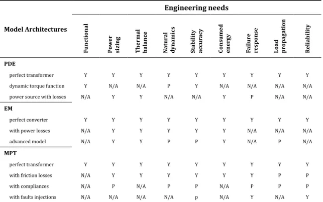
Table 1-3 Model architectures of EMA power devices vs. engineering needs
Model Architectures Engineering needs Fu nc tio na l P ow er siz ing Ther ma l balan ce Na tu ral dyn am ics Stab ili ty ac cu rac y Cons u me d ene rgy Fail u re respo nse Load pro p aga tio n R el iab ili ty PDE perfect transformer Y Y Y Y Y Y Y Y Y
dynamic torque function Y N/A N/A P Y N/A N/A N/A N/A power source with losses N/A Y Y N/A N/A Y P N/A N/A EM
perfect converter Y Y Y Y Y Y Y Y Y
with power losses N/A Y Y Y Y Y N/A N/A N/A
advanced model N/A Y Y P P Y N/A P N/A
MPT
perfect transformer Y Y Y Y Y Y Y Y Y
with friction losses N/A Y Y Y Y Y Y P P
with compliances N/A P N/A P P N/A P P P
with faults injections N/A N/A N/A N/A p N/A Y N/A Y
Note: Y means yes; P means possibly but depending on relative level; N/A means not applicable.
Typically, the EMA model can be developed for simulation aided conceptual design (architectures and function), control design, thermal balance, mean and peak power drawn,

![Fig. 3-10 Switching losses as function of current for different DC supply [11]](https://thumb-eu.123doks.com/thumbv2/123doknet/11438593.289955/101.892.272.638.311.587/fig-switching-losses-function-current-different-dc-supply.webp)