HAL Id: hal-01119719
https://hal.archives-ouvertes.fr/hal-01119719
Submitted on 23 Feb 2015HAL is a multi-disciplinary open access
archive for the deposit and dissemination of sci-entific research documents, whether they are pub-lished or not. The documents may come from teaching and research institutions in France or abroad, or from public or private research centers.
L’archive ouverte pluridisciplinaire HAL, est destinée au dépôt et à la diffusion de documents scientifiques de niveau recherche, publiés ou non, émanant des établissements d’enseignement et de recherche français ou étrangers, des laboratoires publics ou privés.
Broadband Loaded Cylindrical Monopole Antenna
Solene Boucher, Ala Sharaiha, Patrick Potier
To cite this version:
Solene Boucher, Ala Sharaiha, Patrick Potier. Broadband Loaded Cylindrical Monopole Antenna. Proceedings of the International Symposium on Antennas & Propagation (ISAP), 2013, Oct 2013, Nanjing, China. �hal-01119719�
Broadband Loaded Cylindrical Monopole
Antenna
Solene Boucher (lJ, Ala Sharaiha(2J, Patrick Potier (l
(I)DGA-Maitrise de l'information, France,
(2)
Institute of Electronic and Telecommunications of Rennes, UEB, URi, 263 Avenue du general Leclerc, France.Ahstract-A broadband printed monopole antenna based on the variation of the conductivity along its length is proposed .. The result indicates that a non-monotonous repartition provides interesting performances in terms of impedance bandwidth but also concerning antenna gain. The achievement of the method is demonstrated through its application, using the carbon fibers to perform this conductivity variation. Monopole antenna presents a large impedance bandwidth of 123% with an interesting gain. Measurement and simulation present a good agreement.
I.
INTRODUCTION
With the rapid development of communication standards, wide band antennas are needed. Several authors have suggested widening monopole antenna bandwidth by resistive loading continually [1 ,2]. This kind of resistive distribution leads to a very wide bandwidth but damages significantly antenna gain and its efficiency becomes very low. Antenna characteristics could be improved by modifying the resistive profile.
In this paper, we propose to use a variable conductivity along the antenna length applying an optimized profile which gives a broadband impedance bandwidth, a stable radiation pattern, a stable gain level over a large bandwidth especially in the horizontal plane and a higher radiation efficiency. The values of conductivity used is achieved by using various materials such as copper and specially carbon fibers for which we can easily tune its conductivity by modifying the concentration of carbon nanofibers [3]. The main aim is to find a compromise between a large impedance bandwidth at -5 dB of reflection coefficient and a good efficiency. So, a new broadband monopole antenna is presented working in the VHF-UHF band. Simulation results and measurements are presented in order to illustrate the characteristics of the proposed antenna.
II.
ANTENNA DESIGN
The goal of our study is to broaden impedance bandwidth by varying the conductivity along the length of the monopole antenna and maintaining a stable gain level especially in horizontal plane (xOy, 8=0°). For this, we have used a multi objective optimization software named mode Frontier _ ,
Esteco coupled with a three-dimensional time domain
software named Microwave Studio _ , CST. The selected
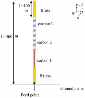
method for optimization is based on a non-dominated sorting genetic algorithm [4]. The monopole antenna is composed of five equal segments length of 50 mm and 20 mm of diameter (figure 1). Brass carbon 3 L=500 m carbon 2 carbon I Brass Ground plane Feed point
Fig
1 .Monopole antenna geometry.
The first segment and last segment is made of Brass and the three other segments was made of carbon tubes.
The optimization solver suggests a distribution conductivity law with a minimum value placed not at the extremity of the monopole antenna as a classical Wu-King profile, but in its centre as shown in Table 1 .
Segment Carbon 1 Carbon 2 Carbon 3 TABLE I
CONDUCTIVITY VALUES
Conductivity (S/m) Equivalent resistance (Q)
2 1 59
0.5 6294
In Figure 2, we present the reflection coefficient of this antenna as well as the gain for 8=00 (horizontal plane).
5 - - - ; - - - i - - - S1 1
(dB)
I:
:
---
Gain (dBi) :
... - _1 _ _ .... .... --... , : I I - - - J� I - - � - - - --\ � - - - � -- - - �.;.:;:.: , .,." I I j\ ... " I , : '\ .. ... " -I - -' ! -5 - - -I - - - � - - - � I I I I I , I , I -1 0 - -1- - - � - - - 4 - - - � - - - � , I I , I I I , - 15 -�- - - � - - - � - - - � - - - � , I I I ! I I I I J , -20 �----�---�---�----� o 0 . 5Frequency
1 .5 2 (GHz
)Fig
3.Simulation of monopole antenna retlection coetlicient and gain in
horizontal plane
(8=0°)
vs. frequency.
We can note that the gain level stays quite constant from
300 MHz to 900 MHz in the Oy axis direction. The maximum gain reaches a value of 2 dB. As for the impedance matching, we obtain 121% of bandwidth for -5 dB of reflection
coefficient.
Ill.
MEASUREMENT RESULTS
A prototype has been realized. The five segments are held by a dielectric support and mounted on a circular ground plane of 800 mm of diameter as shown in Figure 3. It is fed by a coaxial cable fixed on a SMA connector soldered on the monopole antenna.
The carbon tubes are formed by winding on a mandrel fabric carbon fibers impregnated with resin, which is horizontally or vertically deposit on the tubular segment. On curing the resin, the reinforcing strip is integrated with the tubular member.
Fig
3.Picture of the realized antenna.
The obtained carbon segments (1-3) conductivity are : 468
SM, 3 Sim and 2 Sim respectively. Figure 4 shows monopole antenna reflection coefficient in simulation and in measurement using the new values. We note the conductivity values are different from the optimized value. We simulate again the prototype with the realized conductivity and compare results to measurements.
- - - -�- - - -r- - - -� -Simulation I I - - -Mesure _ _ _ _ _ _ _ _ _ _ _ _ _ L _ _ _ _ _ _ _ _ _ _ _ _ _ _ J I I I - 1 0 �----�---�---�----� o 0 . 5
Frequency
1. 5 2 (GHz
)Fig
4.Simulated and measured retlection coetlicients vs. trequency.
A double band behaviour at -6 dB of reflection coefficient is observed in Figure 4, starting at 1 80 MHz MHz to 500 MHz GHz and from 650 MHz to beyond 1 GHz. We note a good agreement between simulation and measurement.
The radiation measurements were performed in an anechoic chamber. In Figures 5, we present at 300 MHz, 600 MHz and 900 MHz, the measured E-plane radiation patterns compared with the simulation.
-900 -900
(a) (b)
Fig 5. Simulated and measured radiation patterns in E plane at (a) 300 MHz,
(b) 600 MHz and ( c) 900 MHz
o - - - -�- - - -T- - - -�- - - -l -5 � - 1 0 -� c�
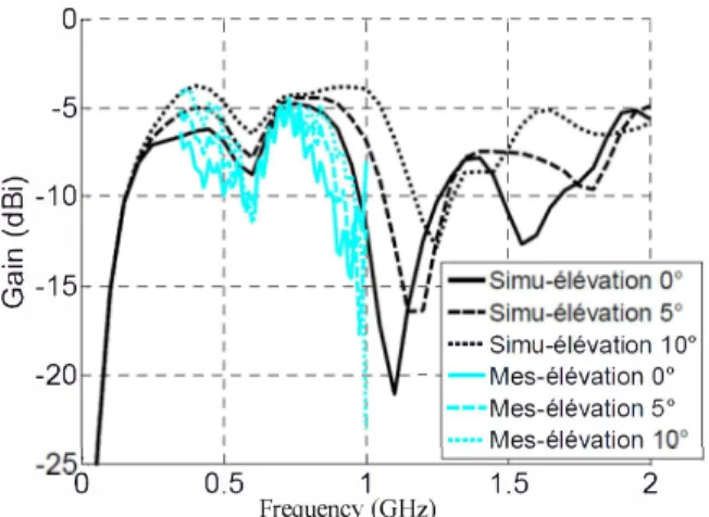
- 1 5 -20 ••••• Simu-elevation 1 0° - -Mes-elevation 0 ° - - -Mes-elevation 5 ° .••.• Mes-elevation 10° -25 LL---'---'---'======----' o 0 . 5Frequency (GHz)
1 1 . 5 2Fig 6. Simulated and measured realized gain vs. frequency for 3 elevations.
In figure 6, we present the measured and simulated gain for various values of elevation angle (8=0°, 8=5° and 8=1 0°) .. We observe that gain value is quite stable for a more than 100% of bandwidth.IV.
CONCLUSION
A broadband monopole antenna has been fabricated in varying conductivity values along antenna length. Its impedance bandwidth is about 120% in VHF-UHF band if we realize the optimized value. Its gain in one direction has a correct level because of the introduction of high conductive material at feeding position.
ACKNOWLEDGMENT
The authors would like to thank the DGA (Defense Depart ment) and COMROD France for the financial support .
REFERENCES
[I] Altshuler, "The travelling-wave linear antenna" ,
IRE Transactions onAntennas and Propagation,
Vol. 9, Issue 4, pp. 324-329, July 1961
[2] T. T. Wu and
nonrefiecting resistive loading",
RW P. King, "The cylindrical antenna with
IEEE Transactions on Antennas and
Propagation,
Vol. 13, Issue 3, pp. 369-373, May 1965
[3]
J -H."M icrostructure and resistivity of carbon nanotube and nanofiber/epoxy
Du, Z Ying, S Bai, F. Li,
CSun and H-M. Cheng,
matrix nanocomposite"
tNT J NANOSCt, 1(5-6),719-723,200
[4] K. Deb,
multiobjective genetic algorithm: NSGA-II",
APratap, S Agarwal and T. Meyarivan, "A fast and elitist
IEEE Transactions on