HAL Id: hal-02333678
https://hal-univ-rennes1.archives-ouvertes.fr/hal-02333678
Submitted on 25 Oct 2019
HAL is a multi-disciplinary open access
archive for the deposit and dissemination of
sci-entific research documents, whether they are
pub-lished or not. The documents may come from
teaching and research institutions in France or
abroad, or from public or private research centers.
L’archive ouverte pluridisciplinaire HAL, est
destinée au dépôt et à la diffusion de documents
scientifiques de niveau recherche, publiés ou non,
émanant des établissements d’enseignement et de
recherche français ou étrangers, des laboratoires
publics ou privés.
Unit-cell design for antenna arrays efficiently matched to
uni-travelling-carrier photodiodes
A. Pascual, L.E. Garcia-Munoz, R. Sauleau, D. Gonzalez-Ovejero
To cite this version:
A. Pascual, L.E. Garcia-Munoz, R. Sauleau, D. Gonzalez-Ovejero. Unit-cell design for antenna
ar-rays efficiently matched to uni-travelling-carrier photodiodes. 2019 44th International Conference
on Infrared, Millimeter, and Terahertz Waves (IRMMW-THz), Sep 2019, Paris, France. pp.1-2,
�10.1109/IRMMW-THz.2019.8874017�. �hal-02333678�
Abstract— We present an antenna array with a backing
reflector that allows one to obtain efficient matching to integrated sources or loads with low input resistance. In the infinite array limit, it is possible to describe the proposed unit-cell as an equivalent network with closed-form expressions for its different constituents. This analytic approach enables the preliminary design of arrays with improved matching efficiency for optimum power transmission/reception. The proposed solution has enabled an improved matching to a uni-travelling-carrier photodiode with a maximum improvement of 3 dB in the radiated power with respect to a 72-Ω antenna, and featuring a 50% bandwidth.
I. INTRODUCTION
onjugate impedance matching between the source (or load) and the antenna is pivotal for efficient radiation of power (or its reception). In particular, it is a critical point in the photonic generation and radiation of millimetrer and sub-millimetrer wave signals with Uni-Travelling-Carrier Photodiodes (UTC-PD) or its reception with zero-bias Schottky Barrier Diodes (SBD). Both devices typically present an input resistance that is generally smaller than 50 Ω and ranges from a few Ohms to some tens of Ohms, with a negative imaginary part (capacitive) [1, 2].
The relatively low radiated power is one of the main drawbacks of photonic generation at these wavelengths. Therefore, solutions to increase the emitted power are actively sought. Previous efforts to increase the matching efficiency to photonic sources rely on the use of matching networks [1], resonant antennas [2], [3], and connected arrays [4]. In this paper, we have developed an equivalent network model for antenna arrays backed by a reflector. This equivalent model offers a simple framework to study an array backed by either a metallic grid or ground plane and may be used to conceive preliminary designs of photomixing arrays.
II. EQUIVALENT MODEL
Infinite phased array antennas and their corresponding equivalent networks have been extensively studied in the past. Their importance relies on the fact that the array can be decomposed in equivalent unit cells, as originally stated by Wheeler [5]. The infinite array approach allows one to work with an antenna element in which the mutual coupling is directly taken into account by the formulation, and, in addition, it can modeled by an equivalent network that allows one to extract the antenna input impedance [6]. The antenna reactance is modelled by combination of lumped elements whereas the dielectric regions are represented by transmission line sections. Here, we will use a network similar to that in [6] to optimize the structure for maximum radiated power.
Fig. 1 shows the geometry and equivalent network of the proposed unit-cell, which is square and lies at the interface between air and Silicon half-spaces. We assume that the Silicon
half space is terminated in a lens that produces no reflections. Every antenna (printed in 0.350-µm thick gold) is fed by an ideal lumped generator with identical amplitude and phase (broadside radiation). The pitch p of the unit-cell satisfies p < λSi to avoid grating lobes, and the antenna geometry (see Fig. 1, bottom right) is defined by three variables: the gap with the neighbor antenna in the same row, g, the semi-bow angle, ϴ, and the length of the oblique section, lo. These parameters
would define the antenna self-reactance, X0, if there was no
backing reflector. X0 is modelled by an inductor in series with a
capacitor in the equivalent network. In addition, the gap region with the neighbor antenna can be either bare (as shown in Fig. 1) or include an interdigital capacitor, which adds an extra degree of freedom to control the impedance of the antenna. The unit-cell geometry is completed with a metallic grid (printed in 1-µm thick gold). This grid backs the antenna in the air region at a distance h, and it is modelled by an inductance X, given by [7]. The grid is defined by its period D, strip width w and orientation. If w approaches D, the grid simply becomes a ground plane.
A. J. Pascual
1, L.E. García-Muñoz
2,R. Sauleau
1and D. González-Ovejero
11Univ Rennes, CNRS, IETR (Institut d’Electronique et de Télécommunications de Rennes) - UMR 6164, F-35000, Rennes, France.
2Universidad Carlos III de Madrid, Leganés 28911, Madrid, Spain
Unit-cell design for antenna arrays efficiently matched to
uni-travelling-carrier photodiodes
C
Fig. 1. 3D layout of the unit-cell of the infinite array with the antenna on the
interface and reflector (grid) on the air side (left). Corresponding equivalent network (middle), and parameters used to define the antenna geometry (right).
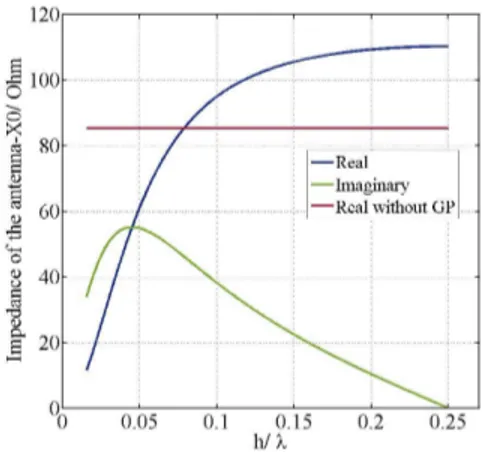
Fig. 2. Antenna impedance computed from the equivalent network of Fig.
1, excluding X0, when backed by a ground plane reflector (Real and
To better understand the effect and optimum position of the reflector, the proposed equivalent network is used to compute the contribution of a ground plane to the antenna impedance (Fig. 2). Examination of Fig. 2 indicates that, if placed at a distance h < λ/4, the ground plane contributes inductively to the antenna impedance and helps, thus, to cancel out the capacitive part of the UTC-PD. Furthermore, if placed at a close distance to the antenna (h/λ < 0.07) the resulting antenna radiation resistance is lower than the one without backing reflector. This feature also contributes to a more efficient matching to the UTC-PD. In practice, a low radiation resistance (< 50 Ω) produces better matching efficiency to the photodiode, but can compromise radiation efficiency. Hence, ohmic losses RΩ have
to be included in the model and a trade-off must be found for practical designs.
Finally, it is important to note that the presented network equivalent is approximate in the sense that it neglects interaction of the reflector with the reactive fields of the antenna. However, these reactive fields are more intense in the Silicon half-space, so the reflector can be placed close to the antenna (h/λ < 0.05) without affecting largely the self-reactance and maintaining an acceptable accuracy of the predictions of the equivalent network.
III. ARRAY SYNTHESIS AND RESULTS
A. Synthesis
One can derive closed-form expressions for the different elements that comprise the network equivalent of Fig. 1 as a function of the unit-cell geometrical parameters. After determining these circuit elements for a given geometry, it is simple to calculate the antenna active input impedance, ZIN, and radiation efficiency. Once these two quantities are known, an optimization algorithm is used to find the optimum geometry of the unit-cell (Fig. 4) for a given source impedance.
B. Simulation results
As an example, we have used our model to yield approximate conjugate matching to the UTC photodiode presented in [1]. The matching efficiency can be increased at the cost of bandwidth. In this case, the objective is to get a 3 dB power drop with relative bandwidth of 50%. Fig. 3 shows the results obtained by the circuit model, by full-wave simulations (HFSS), for an ideal antenna with constant ZIN = 72 Ω, and for the matched solution in [1]. In turn, Fig. 4 shows the optimized geometry of the unit-cell. In this case, an interdigital capacitor gives better results than a gap capacitor, whereas the grid reflector yields slightly higher power radiated towards the Silicon half-space than a ground plane. The former structure presents the additional advantage of allowing the possibility of back illumination of the photodiodes.
IV. SUMMARY
This abstract presents the design of an array unit-cell to improve the matching efficiency of mm- and sub-mm wave antennas to sources (like UTC-PD) and loads (such as SBD) with a low input resistance and capacitive reactance. The proposed method has been illustrated with an example that shows an improvement in the matching efficiency to a UTC-PD with respect to other configurations, while preserving a wide bandwidth of 50%. In the future, practical array conceptions
will include finite array sizes, illumination means (such as waveguides in lateral feed photodiodes, for a 2 by 2 configuration) and lines to bias the photodiodes.
REFERENCES
[1] H. Ito et al., “High-power photonic millimeter wave generation at 100 GHz using matching-circuit-integrated uni-travelling-carrier photodiodes,” IEE
Proc. – Optoelectron., vol. 150, no. 2, pp. 138-142, 2003.
[2] M. Hoefle et al., “Compact and sensitive millimetre wave detectors based on low barrier Schottky diodes on impedance matched planar antennas,” J.
Infrared Millimeter Terahertz Waves, vol. 35, no 11, pp. 891-908, 2014.
[3] J. Montero et al., “Meander dipole antenna to increase CW THz photomixing emitted power.” IEEE Trans. Antennas Propag., vol. 62, no. 9, pp. 4868-4872, 2014.
[4] M. R. Konkol et al., “High-power photodiode-integrated-connected array antenna,” J. Lightwave Technol., vol. 35, no 10, pp. 2010-2016, 2017. [5] H. A. Wheeler, “The radiation resistance of an antenna in an infinite array
or waveguide,” Proc. I. R. E., pp. 478-487, 1947.
[6] E. A. Alwan, K. Sertel, and J. L. Volakis, “Circuit model based optimization of ultra-wideband arrays,” Proc. 2012 IEEE Int. Symp.
Antennas Propag., pp. 1-2, 2012.
[7] O. Luukkonen et al., “Simple and accurate analytical model of planar grids and high-impedance surfaces comprising metal strips or patches,” IEEE
Trans. Antennas Propag., vol. 56, no. 6, pp. 1624-1632, 2008.
Fig. 3. The photodiode equivalent circuit in [1] is used to calculate the power
radiated by an ideal 72-Ω antenna (green-dotted curve), delivered to a 50-Ω load with matching circuit (red triangles), and antenna in an optimized array configuration (blue line for the equivalent network, whereas the blue squares correspond to full-wave simulations carried out with ANSYS HFSS).
Fig. 4. Optimized structure of the array unit-cell and geometrical parameters
(g = 35 µm, p = 300 µm) for efficient matching at 100 GHz of the UTC-PD presented in [1].
![Fig. 4. Optimized structure of the array unit-cell and geometrical parameters (g = 35 µm, p = 300 µm) for efficient matching at 100 GHz of the UTC-PD presented in [1].](https://thumb-eu.123doks.com/thumbv2/123doknet/11303824.281569/3.918.504.828.397.566/optimized-structure-array-geometrical-parameters-efficient-matching-presented.webp)
