HAL Id: tel-01760704
https://pastel.archives-ouvertes.fr/tel-01760704
Submitted on 6 Apr 2018
HAL is a multi-disciplinary open access
archive for the deposit and dissemination of sci-entific research documents, whether they are pub-lished or not. The documents may come from teaching and research institutions in France or abroad, or from public or private research centers.
L’archive ouverte pluridisciplinaire HAL, est destinée au dépôt et à la diffusion de documents scientifiques de niveau recherche, publiés ou non, émanant des établissements d’enseignement et de recherche français ou étrangers, des laboratoires publics ou privés.
Design, Fabrication and Application of Polymeric
Porous Media
Yajie Li
To cite this version:
Yajie Li. Design, Fabrication and Application of Polymeric Porous Media. Mechanics of materials [physics.class-ph]. Ecole nationale supérieure d’arts et métiers - ENSAM; Tongji university (Shanghai, Chine), 2018. English. �NNT : 2018ENAM0009�. �tel-01760704�
N°: 2009 ENAM XXXX
Arts et Métiers ParisTech - Campus de Xxxx Nom de l’Unité de recherche
2018-ENAM-0009
École doctorale n° 432 : Science des Métiers de l’ingénieur
(et école partenaire cotutelle)
présentée et soutenue publiquement par
Yajie LI
le 09 Mars 2018 (09 March 2018)
Design, Fabrication and Application of Polymeric Porous Media
Conception, Fabrication et Application de Milieux Poreux Polymériques
Doctorat ParisTech
T H È S E
pour obtenir le grade de docteur délivré par
l’École Nationale Supérieure d'Arts et Métiers
Spécialité “Mécanique - Matéraux ”
And
Tongji University
Specialty “Material Science and Engineering”
Directeur de thèse : Azita AHMADI
Co-encadrement de la thèse : Aziz OMARI and Hongting PU
T
H
È
S
E
JuryM. Jie CHEN, Professeurdes Universités, Shanghai University Président
M. Olivier ATTEIA, Professeur des Universités, INP Bordeaux, ENSEGID Rapporteur
M. Hongbin ZHANG, Professeurdes Universités, Shanghai Jiao Tong University Rapporteur
Mme. Azita AHMADI, Professeur des Universités, Arts et Métiers ParisTech Examinateur
M. Aziz OMARI, Professeur à Bordeaux, INP/ENSCBP Examinateur
M. Hongting PU, Professeurdes Universités, Tongji University Examinateur
M. Henri BERTIN, Directeur de Recherche CNRS, I2M Examinateur
I
ABSTRACT
Due to the combination of the advantages of porous media and polymer materials, polymeric porous media possess the properties of controllable porous structure, easily modifiable surface properties, good chemical stability, etc., which make them applicable in a wide range of industrial fields, including adsorption, battery separator, catalyst carrier, filter, energy storage, etc. Although there exist various preparation methods, such as template technique, emulsion method, phase separation method, foaming process, electrospinning, top-down lithographic techniques, breath figure method, etc., the large-scale preparation of polymeric porous media with controllable pore structures and specified functions is still a long-term goal in this field, which is one of the core objectives of this thesis. Therefore, in the first part of the thesis, polymeric porous media are firstly designed based on the specific application requirements. Then the designed polymeric porous media are prepared by the combination of multilayer coextrusion and traditional preparation methods (template technique, phase separation method). This combined preparation method has integrated the advantages of the multilayer coextrusion (continuous process, economic pathway for large-scale fabrication, flexibility of the polymer species, and tunable layer structures) and the template/phase separation method (simple preparation process and tunable pore structure). Afterwards, the applications of the polymeric porous media in polycyclic aromatic hydrocarbons adsorption and lithium-ion battery separator have been investigated.
More importantly, in the second part of the thesis, numerical simulations of particle transport and deposition in porous media are carried out to explore the mechanisms that form the theoretical basis for the above applications (adsorption, separation, etc.). Transport and deposition of colloidal particles in porous media are of vital important in other applications such as aquifer remediation, fouling of surfaces, and therapeutic drug delivery. Therefore, it is quite worthy to have a thorough understanding of these processes as well as the dominant mechanisms involved. In this part, the microscale simulations of colloidal particle transport and deposition in porous media are achieved by a novel colloidal particle tracking model, called 3D-PTPO (Three-Dimensional Particle Tracking
model by Python® and OpenFOAM®) code. The particles are considered as a mass point during
transport in the flow and their volume is reconstructed when they are deposited. The main feature of the code is to take into account the modification of the pore structure and thus the flow streamlines due to deposit. Numerical simulations were firstly carried out in a capillary tube considered as an element of an idealized porous medium composed of capillaries of circular cross sections to revisit
II
the work of Lopez and co-authors by considering a more realistic 3D geometry and also to get the most relevant quantities by capturing the physics underlying the process. Then microscale simulation is approached by representing the elementary pore structure as a capillary tube with converging/diverging geometries (tapered pipe and venturi tube) to explore the influence of the pore geometry and the particle Péclet number (Pe) on particle deposition. Finally, the coupled effects of surface chemical heterogeneity and hydrodynamics on particle deposition in porous media were investigated in a three-dimensional capillary with periodically repeating chemically heterogeneous surfaces.
This thesis mainly includes the following aspects:
1) Multilayer polypropylene (PP)/polyethylene (PE) lithium-ion battery (LIB) separators were
prepared via the combination of multilayer coextrusion (MC) and CaCO3 template method (CTM).
The as-prepared separators (referred to as MC-CTM PP/PE) exhibit higher porosity, higher ionic
conductivity and better battery performance than the commercial trilayer separators (Celgard® 2325).
Furthermore, the MC-CTM PP/PE not only possesses the effective thermal shutdown function, but
also shows the strong thermal stability at high temperature (>160 oC). The thermal shutdown
function of MC-CTM PP/PE can be adjusted widely in the temperature range from 127 oC to 165 oC,
which is wider than the Celgard® 2325. The above competitive advantadges which are brought from
the convenient and cost-effective preparation method proposed in this work, make MC-CTM PP/PE a promising alternative to the commercialized trilayer LIB separators.
2) Multilayer PP/PE LIB separators (MC-TIPS PP/PE) with cellular-like submicron grade pore structure are efficiently fabricated by the combination of multilayer coextrusion and thermal induced phase separation (TIPS). In addition to the effective shutdown function, the as-prepared separator
also exihibits a wider shutdown temperature window and stonger thermal stability than the Celgard®
2325, the dimensional shrinkage is negligible until 160 oC. Compared to the commercial separator,
the MC-TIPS PP/PE has a higher porosity (54.6%) and electrolyte uptake (157%), leading to higher
ionic conductivity (1.46 mS cm-1) and better battery performances. The above-mentioned significant
characteristics make the MC-TIPS PP/PE a promising candidate high performance LIB separators. 3) Porous polystyrene (PS) membranes were prepared via the combination of multilayer
coextrusion and CaCO3 template method. Effects of etching time, CaCO3 content, and the membrane
thickness on the porous structures are investigated, which can be used to regulate and control the porous structure. To demonstrate the adsorption performance of porous PS membranes on PAH, pyrene is used as the model compound for polycyclic aromatic hydrocarbon. Compared with PS
III
solid membranes, porous PS membranes exhibit much higher adsorption performance on trace pyrene. The adsorption kinetics and isotherm of porous PS membranes respectively well fit the pseudo second-order kinetics and Freundlich isotherm model.
4) The transport and deposition of colloidal particles at the pore scale are simulated by 3D-PTPO code, using a Lagrangian method. This consists in the three-dimensional numerical modeling of the process of transport and deposition of colloidal particles in capillaries of a circular cross section. The velocity field obtained by solving the Stokes and continuity equations is superimposed to particles diffusion and particles are let to adsorb when they closely approach the solid wall. The particles are considered as a mass point during transport in the flow and their volumes are reconstructed when they are deposited, subsequently the flow velocity field is updated before a new particle is injected. The results show that both adsorption probability and surface coverage are decreasing functions of the particle’s Péclet number. At low Péclet number values, when diffusion is dominant, the surface coverage approaches the Random Sequential Adsorption (RSA) value while at high Péclet number values, it drops drastically.
5) The microscale simulation of colloidal particle deposition in capillaries with converging/diverging geometries (tapered pipe and venturi tube) is approached by the improved 3D-PTPO code. The influence of the particle Péclet number (Pe) and the pore shape on the particle deposition was investigated. The results show that both deposition probability and surface coverage feature a plateau in the diffusion dominant regime (low Pe) and are decreasing functions of Pe in the convection dominant regime (high Pe). The results of the spatial density distribution of deposited particles show that, for the diffusion-dominant regime, the particle distribution is piston-like; while the distribution is more uniform for the convection-dominant regime. In addition, for the venturi tube with steep corners, the density of deposited particles is relatively low in the vicinity of the pore throat entrance and exit due to streamlines modification. The maximum dimensionless surface coverage Γfinal/ΓRSA is studied as a function of Pe. The declining trend observed for high Pe is in good
agreement with experimental and simulation results found in the literature.
6) The coupled effects of surface chemical heterogeneity and hydrodynamics on particle deposition in capillaries are investigated by the microscale simulation using the improved 3D-PTPO code. The porous medium is idealized as a bundle of capillaries and in this study, as an element of the bundle, i.e. a three-dimensional capillary with periodically repeating chemically heterogeneous surface (crosswise strips patterned and chess board patterned) is considered. The dependence of the
IV
(λ), Pe and the reactive area fraction (θ), as well as the spatial density distribution of deposited particles were studied. The results indicate that particles tend to deposit at the leading and trailing edges of the favorable strips, and the deposition is more uniform along the patterned capillary compared to the homogeneous one. In addition, similar to the homogeneous capillary, the maximum
dimensionless surface coverage Γfinal/ΓRSA is a function of Pe. Besides, for the same θ, the deposition
probability is in a positive correlation with λ. Moreover, the overall deposition probability is increasing with θ, which coincides well with the patchwise heterogeneity model.
In the last chapter, the general conclusions and perspectives of this thesis are discussed.
Key Words:
polymeric porous media, multilayer coextrusion, lithium-ion battery separator, PAH adsorption,
microscale simulation, 3D-PTPO (three-dimensional particle tracking model by Python® and
OpenFOAM®), particle transport and deposition
Mots clés:
milieux poreux polymériques, coextrusion multicouche, séparateur de batterie au lithium-ion, l'adsorption de PAH, simulation à l'échelle microscopique, 3D-PTPO (modèle tridimensionnel de
V
CONTENTS
ABSTRACT ... I CONTENTS ...V LIST OF FIGURES ... VII LIST OF TABLES ... XII
CHAPTER 1 GENERAL INTRODUCTION ... 1
1.1CONTEXT AND OBJECTIVES OF THE PRESENT STUDY ... 1
1.2ORGANIZATION OF THE THESIS ... 4
CHAPTER 2 LITERATURE REVIEW ... 6
2.1DESIGN AND FABRICATION OF POLYMERIC POROUS MEDIA ... 6
2.2TRANSPORT OF COLLOIDAL PARTICLES IN POROUS MEDIA ... 19
PART I: PREPARATION OF POLYMERIC POROUS MEDIA FOR LITHIUM-ION BATTERY SEPARATORS AND WATER TREATMENT ... 44
CHAPTER 3 PREPARATION OF MULTILAYER POROUS POLYPROPYLENE/POLYETHYLENE LITHIUM-ION BATTERY SEPARATORS BY COMBINATION OF MULTILAYER COEXTRUSION AND TEMPLATE METHOD ... 44
3.1INTRODUCTION ... 44
3.2EXPERIMENTAL SECTION ... 46
3.3RESULTS AND DISCUSSION ... 50
3.4CONCLUSIONS ... 59
CHAPTER 4 PREPARATION OF MULTILAYER POROUS LITHIUM-ION BATTERY SEPARATORS BY COMBINATION OF MULTILAYER COEXTRUSION AND THERMAL INDUCED PHASE SEPARATION ... 60
4.1INTRODUCTION ... 60
4.2EXPERIMENTAL SECTION ... 61
4.3RESULTS AND DISCUSSION ... 64
4.4CONCLUSIONS ... 71
CHAPTER 5 PREPARATION OF POROUS POLYSTYRENE MEMBRANES VIA MULTILAYER COEXTRUSION AND ADSORPTION PERFORMANCE OF POLYCYCLIC AROMATIC HYDROCARBONS ... 72
VI
5.1INTRODUCTION ... 72
5.2EXPERIMENTAL SECTION ... 73
5.3RESULTS AND DISCUSSION ... 75
5.4CONCLUSIONS ... 86
PART II : TRANSPORT OF COLLOIDAL PARTICLES IN POLYMERIC POROUS MEDIA : NUMERICAL MODELING ... 87
CHAPTER 6 COLLOIDAL PARTICLE DEPOSITION IN POROUS MEDIA IDEALIZED AS A BUNDLE OF CAPILLARIES... 87
6.1INTRODUCTION ... 87
6.2METHODOLOGY AND TOOLS ... 88
6.3RESULTS AND DISCUSSION ... 90
6.4CONCLUSIONS ... 95
CHAPTER 7 THREE-DIMENSIONAL MICROSCALE SIMULATION OF COLLOIDAL PARTICLE TRANSPORT AND DEPOSITION IN MODEL POROUS MEDIA WITH CONVERGING/DIVERGING GEOMETRIES ... 96
7.1INTRODUCTION ... 96
7.2NUMERICAL SIMULATIONS ... 98
7.3RESULTS AND DISCUSSION ... 102
7.4CONCLUSIONS ... 110
CHAPTER 8 THREE-DIMENSIONAL MICROSCALE SIMULATION OF COLLOIDAL PARTICLE TRANSPORT AND DEPOSITION IN CHEMICALLY HETEROGENEOUS POROUS MEDIA ... 113
8.1INTRODUCTION ... 113
8.2NUMERICAL SIMULATIONS ... 115
8.3RESULTS AND DISCUSSION ... 119
8.4CONCLUSIONS ... 128
CHAPTER 9 CONCLUSIONS AND PERSPECTIVES ... 129
ACKNOWLEDGEMENT ... 132
REFERENCES ... 133
NOMENCLATURE ... 150
VII
List of Figures
Figure 1.1 The summary of the classification of materials [3] ... 1 Figure 1.2 Illustration of representative natural and synthesized porous materials: (a) bamboo;
(b) honeycomb; (c) alveolar tissue in mouse lung; (d) ordered macroporous polymer from direct templating; (e) porous aluminum; (f) porous silica [5] ... 2 Figure 2.1 Schematic illustration of different morphology of pores [18] ... 6 Figure 2.2 Illustration of pore surface, pore size, pore geometry, and framework structure of
porous media [5] ... 7 Figure 2.3 Classification of porous media according to pore size [21] ... 7 Figure 2.4 Different pore configurations: (a) foams; (b) interconnected pore network; (c)
powder compacts; (d) porous media produced from a powder with plate-like particles; (e) porous media consisting of fiber-shaped particles; (f) large pores connected by small pores; (g) both small pore networks and large pore networks [18] ... 8 Figure 2.5 Schematic illustration of fabrication of (a) spherical porous polymers, (b) tubular
porous polymers, (c) ordered macroporous polymers [5] ... 10 Figure 2.6 Summary of removal conditions of various templates [5] ... 11
Figure 2.7 schematic representation of a binary phase diagram of a polymer solution [46] ... 13
Figure 2.8 Schematic representation for the change from conventional emulsion, through emulsion with the maximum packing fraction (74 vol%), to HIPE when increasing the volume fraction of internal phase [5] ... 14
Figure 2.9 Schematic representation of the problem[108]. (a) The small circle of radius a
represents the moving sphere with a corresponding incoming impact parameter bin. The circle of radius b represents the fixed obstacle (a sphere or a cylinder). The empty circle represents the position of the suspended particle as it crosses the symmetry plane normal to
the x-axis. The surface-to-surface separation ξ and its minimum valueξmin are also shown.
(b) Representation of the conservation argument used to calculate the minimum separation. The unit vector in the radial direction d, the velocity components in the plane of motion, both far upstream (S∞) and at the plane of symmetry (S0) are shown ... 25
Figure 2.10 Three filtration mechanisms of particle transport in porous media[132] ... 27
Figure 2.11 Key factors controlling engineered nanoparticle transport in porous media [144] ... 32
Figure 2.12 Schematic representation of the modeled surface charge heterogeneity. The square collector of height L consists of rectangular strips with alternate regions that are favorable
VIII
(gray) and unfavorable (white) to deposition of widths w and b, respectively. The total width of a favorable and unfavorable strip gives the pitch, p. The deposited spherical
particles of diameter d = 2ap have their centers constrained to lie within the favorable strips
[161]
... 39 Figure 2.13 Periodic surface patterns: (a) lengthwise strips, (b) crosswise strips, (c) patchwise
pattern. Dark regions represent heterogeneous patches, light regions are the homogeneous surface. In each case the percent heterogeneous coverage is 50% [177] ... 40
Figure 2.14 Schematic of a patterned microchannel geometry with Poiseuille flow profile [188] 43
Figure 3.1 Preparation of MC-CTM PP/PE via the combination of multilayer coextrusion and CaCO3 template method ... 48
Figure 3.2 (a) SEM image of the surface of the MC-CTM PP/PE. (b) SEM image of the cross-section (fractured in liquid nitrogen) of the MC-CTM PP/PE. (c) Optical microscope image of the MC-CTM PP/PE with multilayer structure (cross-section) ... 51 Figure 3.3 Stress-strain curve of MC-CTM PP/PE at room temperature ... 52
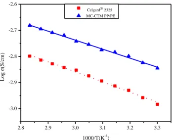
Figure 3.4 Arrhenius plots of ionic conductivity of MC-CTM PP/PE and Celgard® separator at
elevated temperatures (from 30 to 80 oC) ... 53
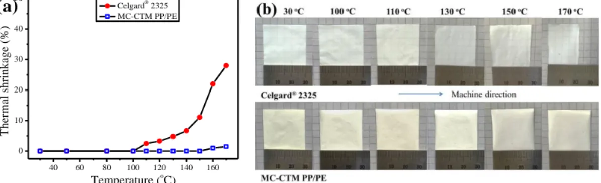
Figure 3.5 (a) Thermal shrinkage of MC-CTM PP/PE and Celgard® 2325 as a function of heat
treatment temperature; (b) photographs of MC-CTM PP/PE and Celgard® 2325 after heat
treatment at different temperature for 0.5 h ... 54 Figure 3.6 (a) Impedance vs. temperature curves for cells containing different separators,
commercial PE separator (SK Energy), commercial PP/PE/PP separator (Celgard® 2325),
and MC-CTM PP/PE; (b) DSC curve of MC-CTM PP/PE ... 55 Figure 3.7 Chronoamperometry profiles of Li/electrolyte soaked separator/Li cells assembled
with MC-CTM PP/PE and Celgard® separator by a step potential of 10 mV ... 56
Figure 3.8 Linear sweep voltammetry (LSV) curves of Li/electrolyte soaked separator/SS cells
assembled with MC-CTM PP/PE and Celgard® separator with a scanning rate of 5 mV s-1
over voltage range from 2 to 7 V ... 57
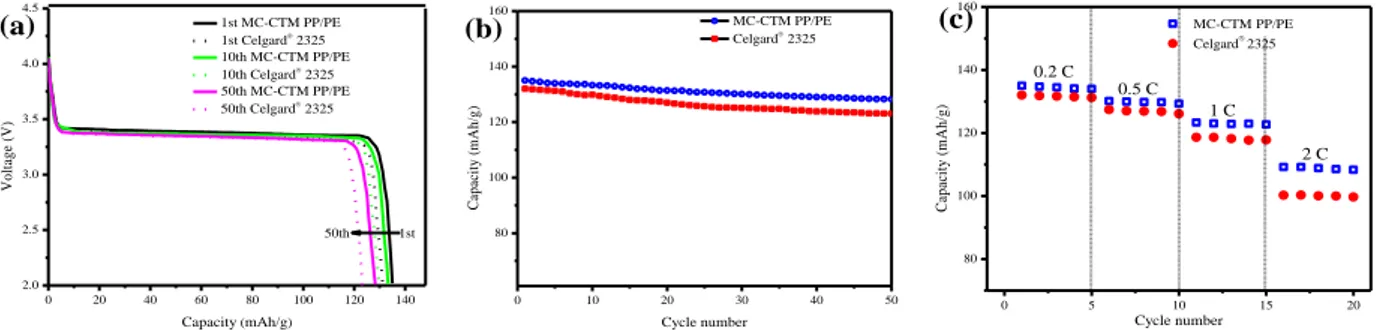
Figure 3.9 Electrochemical performances of MC-CTM PP/PE and Celgard® separator tested in
Li/separator/LiFePO4 configuration, (a) First discharge profiles at 0.2 C-rate, (b) Cycling
performance at 0.2 C-rate, (c) C-rate behavior where the current densities are varied from 0.2 C to 2 C ... 59 Figure 4.1 Schematic illustration showing the preparation process of MC-TIPS PP/PE via the
combination of multilayer coextrusion and thermal induced phase separation ... 62 Figure 4.2 (a) FESEM image and pore size distribution of the surface of MC-TIPS PP/PE; (b)
IX
by liquid nitrogen; (c) Optical microscope image of the cross-sectional multilayer structure of MC-TIPS PP/PE ... 65 Figure 4.3 Stress-strain curve of MC-TIPS PP/PE at room temperature ... 66
Figure 4.4 Temperature dependence of ionic conductivity of MC-TIPS PP/PE and Celgard®
separators ... 67
Figure 4.5 (a) Thermal shrinkage rate of MC-TIPS PP/PE and Celgard® 2325 as a function of
heat treatment temperature; (b) photographs of MC-TIPS PP/PE and Celgard® 2325 after
heat treatment at various temperatures for 0.5 h ... 68 Figure 4.6 (a) Impedance versus temperature curve for cells containing commercial PE
separator (SK Energy), commercial PP/PE/PP separator (Celgard® 2325), and MC-TIPS
PP/PE. (b) The DSC curve of MC-TIPS PP/PE ... 69 Figure 4.7 (a) Chronoamperometry profiles of LM/electrolyte soaked separator/LM cells
assembled with MC-TIPS PP/PE and Celgard® sepatator by a step potential of 10 mV. (b)
LSV curves of LM/electrolyte soaked separator/SS cells assembled with MC-TIPS PP/PE
and Celgard® separator with a scanning rate of 5 mV s-1 over voltage range from 2 to 6 V
... 70
Figure 4.8 Battery performances of MC-TIPS PP/PE and Celgard® separator tested in
Li/separator/LiFePO4 configuration. (a) Cycling performance at 0.2 C-rate and (b) C-rate
behavior where the current densities ranging from 0.2 C to 2 C ... 71 Figure 5.1 (a) Schematic representation of the two-component multilayer coextrusion system, (b)
Preparation of porous PS membranes via the combination of multilayer coextrusion and CaCO3 template method ... 74
Figure 5.2 Optical microscope images (reflection mode) of the cross-section of
LDPE/PS(CaCO3) coextrusion films with multilayer structure, (a) 16 layers, (b) 32 layers,
and (c) 64 layers ... 76
Figure 5.3 Optical microscope images (transmission mode) of PS(CaCO3) membranes (40 wt%
CaCO3), (a) blended by the twin-screw extruder followed by compression molding, (b)
prepared via multilayer coextrusion ... 76
Figure 5.4 Digital photographs of single layer PS(CaCO3) membranes (a) before and (b) after
etched in 15 wt% HCl solution for 48 h ... 77 Figure 5.5 SEM images of the frozen brittle fracture surface of porous PS membranes (40 wt%
CaCO3, etched for 48 h) with different thickness, (a) 20 µm, (b) 10 µm, (c) 5 µm. ... 78
Figure 5.6 SEM images of the surface of polystyrene membranes with different etching time (in 15 wt% HCl solution), (a) before etching, (b) etched for 24 h, (c) etched for 48 h ... 78
X
Figure 5.7 Etching (in 15 wt% HCl solution) kinetics of CaCO3 in the membranes (40 wt%
CaCO3 in the membranes, thickness 5 µm) ... 79
Figure 5.8 SEM images of the frozen brittle fracture surface of PS membranes with different
CaCO3 contents after etched in 15 wt% HCl solution for 48 h, (a) 20 wt% CaCO3, (b) 40
wt% CaCO3 ... 79
Figure 5.9 (a) Fluorescence spectra of pyrene in aqueous solution after adsorbed by porous PS membranes (6#) for 12 h; (b) effects of the amount of porous PS membranes (6#) on the residual concentration of pyrene solution, which can be calculated according to the fluorescence intensity of the solution at 370 nm; the initial concentration of pyrene solution is 130 ppb ... 81 Figure 5.10 Fluorescence spectra of pyrene in aqueous solution after adsorbed for different time
by (a) 1# membranes, (b) 2# membranes, (c) 3# membranes, (d) 4# membranes, (e) 5#
membranes, and (f) 6# membranes; (g) Adsorption kinetics of pyrene in aqueous solution
by membranes from 1# to 6# with 0.8 g L-1 membranes in the solution, which can be calculated according to the fluorescence intensity of the solution at 370 nm, the initial concentration of pyrene solution is 130 ppb ... 83 Figure 5.11 (a) First-order rates for the adsorption of pyrene by membrane 1# and 6#; (b)
Second-order rates for the adsorption of pyrene by membrane 1# and 6# PS membranes; the
initial concentration of pyrene is 0.13 mg L-1 ... 84
Figure 5.12 Adsorption isotherm for the adsorption of pyrene by porous PS membranes (6#); (b)
the values of lnQeq against lnCeq based on Freundlich isotherm model; (c) the linear
dependence of Ceq/Qeq on Ceq based on Langmuir isotherm model ... 85
Figure 6.1 Variation of deposition probability versus the number of injected particles for different Péclet numbers ... 91 Figure 6.2 Variation of Γ/ΓRSA versus the Péclet number ... 92
Figure 6.3 Visual illustration of adsorbed particles for two different Péclet numbers after the injection of 3000 particles (A) Pe=0.0015 and (B) Pe=150 ... 92 Figure 6.4 Variation of porosity values versus N at different Pe ... 93 Figure 6.5 Variation of permeability reduction versus N at various Pe (A); Hydrodynamic
thickness /2rp of the deposited layer versus Pe (B) [17] ... 94
Figure 7.1 Geometry and meshing of the two configurations considered: (a) tapered pipe; (b) venturi tube ... 99 Figure 7.2 Sketches of possible particle trajectories: (a) flow through; (b) approaching a
deposited particle (in blue) and bouncing back to the bulk flow (in red); (c) deposited on the wall ... 102
XI
Figure 7.3 Variation of deposition probability versus N at different Pe for the tapered pipe .... 104 Figure 7.4 (a) Spatial distribution of the density of deposited particles along the z coordinate at
different N for Pe=0.0019; (b) 3D sectional view of the tapered pipe at N=200; (c) 3D sectional view of the tapered pipe at N=30000 (the flow occurs from left to right)... 106 Figure 7.5 (a) Spatial distribution of the density of deposited particles along the z coordinate at
different N for Pe=190; (b) 3D sectional view of the tapered pipe at N=200; (c) 3D sectional view of the tapered pipe at N=15000 (Pe=190, the flow occurred from left to right) ... 106 Figure 7.6 Streamline profiles in the tapered pipe without (a) and with (b) deposited particles
(Pe=1.9) ... 106 Figure 7.7 Spatial distribution of the density of deposited particles along the z coordinate at
different N for Pe=0.0014 ... 107
Figure 7.8 Initial streamlines distribution in the venturi pipe at Pe=1.4 and Re=0.48×10⁻⁴ ... 108
Figure 7.9 Variation of dimensionless surface coverage Γ/ΓRSA versus N at different Pe ... 110
Figure 7.10 Variation of Γfinal/ΓRSA versus Péclet number: (a) venturi tube; (b) tapered pipe; (c)
capillary tube; (d) parallel planes of Lopez et al [17]; (e) experimental results of Veerapen et
al [274] ... 110 Figure 8.1 Surface heterogeneity is modeled as alternate bands (patches) of attractive and
repulsive regions on the capillary wall to facilitate systematic continuum type evaluation: (a): Crosswise strips patterned; (b): Chess board patterned. Bright bands (patches) represent positively charged regions, blue bands (patches) represent negatively charged regions, and the particles are positively charged ... 116 Figure 8.2 Sketches of possible particle trajectories: (a) flowing through the capillary; (b)
approaching a deposited particle (in grey line) and bouncing back to the bulk flow (in orange line); (c) approaching repulsive regions (positively charged) on the capillary wall (in grey line) and bouncing back to the bulk flow (in green line); (d) approaching attractive regions (negatively charged) and depositing on the wall ... 119 Figure 8.3 (a) Spatial density distribution of the deposited particles versus the z coordinate at
N=2000, Pe=0.0015 for both heterogeneous (λ=5 and θ=0.5) and homogeneous capillary; (b) schematic representation of particle behavior near the boundaries between the favorable
and unfavorable strips[280]. 3D sectional view of the heterogeneous (c) and homogeneous (d)
capillary (the red small geometries represent the deposited particles; the flow occurred from left to right) ... 120 Figure 8.4 Variation of deposition probability versus the number of injected particles (N) for
XII
Figure 8.5 (a) Determination of the calculation method of the dimensionless surface coverage for heterogeneous capillary, the dotted line stands for the homogeneous capillary. (Pe=0.0015); (b) Variation of the dimensionless surface coverage versus N for heterogeneous capillary with different λ. The inset plot represents the overall particle
deposition probability versus λ with N=5000 (Pe=0.0015) ... 123
Figure 8.6 Variation of dimensionless surface coverage Γ/ΓRSA. (a) Γ/ΓRSA versus N at different Pe; (b) ΓMax/ΓRSA as a function of Pe. (λ=5 and θ=0.5 for the heterogeneous capillary) ... 124
Figure 8.7 (a). 3D sectional view (left: crosswise strips patterned), (right: chess board patterned) of the heterogeneous capillary with deposited particles ; (b) variation of dimensionless surface coverage Γ/ΓRSA versus N for crosswise strips patterned and chess board patterned capillaries. For both cases, θ=0.5, pitch length=3 μm and Pe=0.0015 ... 126
Figure 8.8 (a) 3D sectional view of the heterogeneous capillary with deposited particles, λ=5, Pe=0.0015, θ is ranging from 20% to 100%; (b) variation of the number of deposited particles (n) versus the number of injected particles (N) with different θ; (c) the dependence of the effective collector efficiency (ηeffective/ηf) on θ. (λ=5, Pe=0.0015, N=10000) ... 127
List of Tables
Table 2.1 Existing models for particle deposition in porous media [138] ... 30Table 3.1 Physical properties of MC-CTM PP/PE and Celgard® 2325 ... 51
Table 4.1 Physical properties of MC-TIPS PP/PE and Celgard® 2325 ... 66
Table 5.1 Regulation and controlling of the porosity of PS membranes ... 80
Table 6.1 Detailed parameters of the simulation ... 90
Table 7.1 Parameters used for simulations ... 102
1
Chapter 1 General Introduction
1.1 Context and objectives of the present study
Materials can be divided into dense materials and porous materials according to their density. Figure 1.1 shows a summary of the classification of materials. The study of porous material is an important branch of material science, which plays a significant role in our scientific research and industrial production. Each porous medium is typically composed of a solid skeleton and a void space, which is usually filled with at least one type of fluid (liquid or gas) [1-3]. There are many examples of natural (hollow bamboo, honeycomb, and alveoli in the lungs) and man-made porous
materials (macroporous polymer, porous aluminum, and porous silica), as shown in Figure 1.2 [4, 5].
Polymeric porous medium is one of the most important components of organic porous materials, which is the main object of this thesis. Polymeric porous medium (porous polymer) has the combined advantages of porous media and polymer materials. It possesses high porosity, abundant microporous structure and low density. The various preparation methods, controllable pore structure and easily modified surface properties make the polymeric porous media promising materials in a wide range of application fields including adsorption, battery separator, filter, energy storage,
catalyst carrier, and biomedical science [5]. Therefore, it is quite interesting and worthy to study the
new function of polymeric porous media and to develop a novel preparation method for this widely-used material.
2
Figure 1.2 Illustration of representative natural and synthesized porous materials: (a) bamboo; (b) honeycomb; (c) alveolar tissue in mouse lung; (d) ordered macroporous polymer from direct templating; (e) porous aluminum; (f)
porous silica [5]
Prior to the preparation and realization, the functions and the structures of polymeric porous media should be designed. The foremost aspect to consider is the main functions that we would like to realize in the media, which lead to specific application properties. Secondly, we need to determine the key factors that are directly related to the desired function, such as the pore geometry, pore size and the matrix porosity of the materials. Thirdly, based on the above considerations, the experimental scheme needs to be designed to prepare the polymeric porous media. Although various preparation methods exist, such as template technique, emulsion method, phase separation method, foaming process, electrospinning, top-down lithographic techniques, breath figure method, etc., the large-scale preparation of polymeric porous media with controllable pore structures and specified functions is still a long-term goal in this field, which is one of the core objectives of this thesis. A new approach, forced assembly multilayer coextrusion, has been used to economically and efficiently produce polymers of multilayers with individual layer thickness varying from micron to nanoscale. This advanced polymer processing technique has many advantages including continuous process, economic pathway for large-scale fabrication, flexibility of the polymer species, and the capability to produce tunable layer structures. Therefore, in the part I of this thesis, polymeric porous media are designed based on the specific application requirements and prepared by the combination of multilayer coextrusion and traditional preparation methods (template technique, phase separation method). This approach combines the advantages of the multilayer coextrusion and the template/phase separation method (simple preparation process and tunable pore structure). Afterwards, the applications of the polymeric porous media in PAHs adsorption and lithium-ion battery separator have been investigated.
3
More importantly, the basic mechanism of the above application processes (PAHs adsorption process or lithium-ion transport through separator) is based on the particle transport and deposition in porous media. Thus it is essential to have a thorough understanding of particle transport and deposition processes in porous media as well as the dominant mechanisms involved. In addition, transport and deposition of colloidal particles in porous media is of vital importance to other
engineering and industrial applications [6], such as particle-facilitated contaminants transport [7],
water purification [8], wastewater treatment [9], or artificial recharge of the aquifers [10]. In order to comprehend colloidal particle transport mechanisms in porous media, computational fluid dynamics
(CFD) numerical simulations have been carried out to visualize and analyze the flow field [11].
Taking water filtration as an example, numerical techniques could be used to model the transport and
dispersion of contaminants within a fluid [12]. Basically, there are two fundamental theoretical basis
to study the transport of colloidal particles in porous media, classified as Eulerian and Lagrangian
methods [13, 14]. The Eulerian method describes what happens at a fixed point in space, while the
Lagrangian method implies a coordinate system moving along with the flow [15]. Pore geometries are
often simplified into one or two dimensions to reduce the time consumption of the numerical simulations. However, this simplification restricts the particle motion and reduces the accuracy of the results. Therefore, it is necessary to improve the simulation model to enable three-dimensional
simulations in more realistic geometries [16]. Moreover, particle transport and deposition in
heterogeneous porous media have been an area of intense investigation recently. So far, there are few reported works on the combined effects of hydrodynamics and surface heterogeneity on colloidal particle deposition in porous media. Hence, it is necessary to better understand the mechanisms reponsible for these phenomena, which is one of the objectives of the present work.
The objective of the part II of this thesis is the three-dimensional microscale simulation of colloidal particles transport and deposition in both homogeneous and heterogeneous porous media by means of CFD tools using the Lagrangian method in order to get the most relevant quantities by capturing the physics underlying the process. In order to perform the simulation, a novel colloid
particle tracking model, namely 3D-PTPO (Three-dimensional particle tracking model by Python®
and OpenFOAM®) code using Lagrangian method is developed in the present study. The major
content of the part II of this thesis could be summarized as: firstly, particle deposition behavior is
investigated on a homogeneous cylinder in order to revisit the previous work of Lopez et al. [17] by
considering a more realistic 3D geometry. Indeed their work was limited to a particular geometry restricted to a slot-like geometry unlikely to be encountered in real porous media. In addition, it is necessary to validate the fundamental transport properties during the simulation, since the initial
4
validation part of the model development (involving deposition onto homogeneous collectors) was important for the following simulations of particle transport and deposition in the subsequent more complex pore geometries. Secondly, the three-dimensional numerical modeling of the process of particle transport and deposition in a more complex pore geometry (tappered pipe of venturi tube) of a circular cross section is carried out to explore the influence of pore geometry on the flow field as well as on the particle transport and deposition properties. Thirdly, the 3D-PTPO model is improved by incorporating surface chemical heterogeneity. The combined effects of the surface heterogeneity and hydrodynamics on the particle deposition behavior are investigated.
1.2 Organization of the thesis
The content of this thesis has been subdivided into the following nine chapters:
In Chapter 1, the general overview of the current research topic, the objectives of the thesis, as well as the outline have been explained.
In Chapter 2, firstly, a thorough review of existing work on polymeric porous media has been presented, including the evolution, the detailed preparation methods, as well as the applications. Secondly, particle transport and deposition in porous media has been reviewed. The transport and deposition mechanisms, the research methods, as well as the previous work are all illustrated in details. Particularly, reviews of particle deposition onto homogeneousheterogeneous substrates have been summarized respectively.
In Chapter 3, a facile and continuous method to prepare porous multilayer polypropylene
(PP)/polyethylene (PE) membranes via multilayer coextrusion and CaCO3 template method is
proposed. The physical and electrochemical properties of the separators for lithium-ion batteries (LIBs) have been investigated and compared with the commercial separators.
In Chapter 4, multilayer PP/PE LIB separators with cellular-like submicron grade pore structure are efficiently fabricated by the combination of multilayer coextrusion and thermal induced phase separation (TIPS). The physical and electrochemical properties of the separators have been investigated and compared with the commercial separators.
In Chapter 5, a convenient and continuous method to prepare porous polystyrene (PS) membranes via multilayer coextrusion and template method is proposed. To investigate the
5
adsorption performance of porous PS membranes on PAHs, pyrene is used as the model compound for polycyclic aromatic hydrocarbon.
In Chapter 6, the particle transport and deposition onto a homogenous porous medium composed of a bundle of capillaries of a circular cross section has been carried out to validate the fundamental transport properties, which is important for the following simulations of particle transport and deposition in complex porous media.
In Chapter 7, the particle transport and deposition in homogenous porous media with converging/diverging geometries (tapered pipe and venturi tube) is investigated by the three-dimensional microscale simulation. The influence of the pore geometry and particle Péclet number (Pe) on the particle deposition iss explored.
In Chapter 8, the particle transport and deposition onto capillaries with periodically repeating chemical heterogeneous surfaces (crosswise strips patterned and chess board patterned) is investigated by the three-dimensional microscale simulation. The dependence of the deposition
probability, dimensionless surface coverage (Γ/ΓRSA) on the frequency of the pitches (λ), particle
Péclet number (Pe) and the favorable area fraction (θ), as well as the spatial density distribution of deposited particles have been studied.
In Chapter 9, major conclusions from each chapter are summarized and the perspectives for the future work are discussed.
6
Chapter 2 Literature Review
2.1 Design and fabrication of polymeric porous media
2.1.1
Polymeric porous media
Porous media are defined as solids containing pores. Normally, porous media have the porosity of 0.2-0.95. Pores are classified into two types: closed pores which are isolated from the outside and open pores which connect to the outside of the media. Especially, penetrating pores are a kind of open pores which possess at least two openings located on two sides of the porous media. The different morphology of pores are illustrates schematically in Figure 2.1. Open pores are required for most industrial applications such as filters, carriers for catalysts and bioreactors. This thesis mainly focuses on open pores. Introducing open pores in media, or to say producing open porous media, changes media properties. The decreased density and the increased specific surface area are the two essential changes, which can generate beneficial properties including permeability, filtration effects,
as well as the thermal/acoustic insulation capabilities [18].
Figure 2.1 Schematic illustration of different morphology of pores [18]
There are several significant structural characteristics of porous media including pore size, pore geometry, pore surface functionality, and framework structure such as topology, composition, and
7
employed to evaluate the pore structure; generally, pores with a smaller size contribute predominantly to the generation of materials with high surface area. Pore geometry includes tubular, spherical, and network-type morphologies that can be either assembled into ordered arrays or disorders. In addition to the physical structures, the functionalities of the pore surface and the
framework are also important [19], which can be engineered by post-modification processes or
through the use of functional monomers [20].
Figure 2.2 Illustration of pore surface, pore size, pore geometry, and framework structure of porous media [5]
Porous media can be classified by the above structural characteristics such as pore size, pore geometries and framework materials:
According to the International Union of Pure and Applied Chemistry (IUPAC) recommendation,
the classification of porous media by pore size is shown in Figure 2.3 [21]. Macroporous media are
defined as media with pore size larger than 50 nm in diameter, mesoporous media with pore size in
the range of 2-50 nm, and microporous media with pore size smaller than 2 nm [22].
8
Porous media can also be classified by the pore geometries. Figure 2.4 illustrates the different kinds of pore geometries. Most porous media are foams with the open porosity ranging from 0.7 to 0.95. This configuration can be produced by bubbling the ceramic slurry or by using a large amount of pore forming agent. (Figure 2.4a) An interconnected pore network can be observed in porous glasses produced by a leaching technique that results in the spinodal decomposition, pores are homogenous in both size and shape (Figure 2.4b). Powder compacts have the geometry of opening pores between particles and the pore shape is angular fundamentally. (Figure 2.4c) Porous media produced from a powder with plate-like particles possess the geometry of opening pores between plates (Figure 2.4d). Porous media built up by fiber-shaped particles have the geometry of opening pores between fibers. (Figure 2.4e) Sintered porous materials with pore forming agents possess the configuration of large pores connected by small pores (Figure 2.4f). Porous media consisting of porous particles have the configuration of both small pore networks and large pore networks (Figure 2.4g) [18].
Figure 2.4 Different pore configurations: (a) foams; (b) interconnected pore network; (c) powder compacts; (d) porous media produced from a powder with plate-like particles; (e) porous media consisting of fiber-shaped particles; (f) large pores connected by small pores; (g) both small pore networks and large pore networks [18]
9
More importantly, classification based on the framework materials is of vital important in the application of porous media. Depending on the desired properties such as mechanical strength, chemical stability and high-temperature resistance, materials are selected for porous solid including paper, polymer, metal, glass, and ceramic. Polymeric porous media especially have received an increased level of research interest due to their potential to merge the properties of both porous
materials and polymers [23]. Firstly, porous polymers have the advantages of high surface area and
well-defined porosity [24]. Secondly, the porous polymers possess good processability, which
generates obvious advantages in many applications fields [25]. Thirdly, the diversity of preparation
routes facilitates the construction and design of numerous porous polymers [26]. Finally, the
polymeric frameworks are composed of light elements due to their organic nature, which provides a
weight advantage in many applications [27].
Polymeric porous media have been synthesized [28] by incorporating monomers into well-known
step growth and chain-growth polymerization processes to provide cross-links between propagating polymer chains since the early 1960s, resulting in three-dimensional network materials. In the late 1980s, the copolymerization strategy and the use of discrete molecular porogens were combined to create molecularly imprinted polymers. These materials have been extensively investigated in sensing and catalysis applications [29]. Besides, it is often too fast and difficult to control the polymerization/cross-linking kinetics, yielding the macro-pores rather than the micro-pores. In the
late 1990s, attempts were made [29] to synthesize microporous organic polymer materials from
monomers. Slower bond-forming reactions were adapted promote the formation of pores that closely
match the potential guest molecules dimension [28, 29]. The ability to control the structure of pores and
incorporate desired functionalities into the material has benefited from the great strides being made in the preparation of polymeric porous media by various preparation methods, as summarized in the following chapter.
2.1.2
Preparation methods
The past several years have witnessed an expansion of various methods directed at preparing polymeric porous media, including direct templating, block copolymer self-assembly, and direct synthesis methodologies. These techniques have been developed mainly based on the properties of the raw materials and the targeted applications. Polymeric porous media prepared by different techniques possess different characteristics, such as average pore size, porosity, and mechanical
10 2.1.2.1 Direct templating method
Direct templating method is a simple and versatile approach for the direct replication of the
inverse structure of the preformed templates with stable morphology [5]. A large number of
polymeric porous media have been successfully prepared by direct templating method, including individual spherical porous polymers from solid spherical nanoparticle templates (Figure 2.5a), tubular porous polymers from tubular porous templates (Figure 2.5b), and ordered macroporous
polymers from colloidal crystal templates (Figure 2.5c) [5].
Figure 2.5 Schematic illustration of fabrication of (a) spherical porous polymers, (b) tubular porous polymers, (c) ordered macroporous polymers [5]
There are several requirements for the successful preparation of polymeric porous media by direct templating method. Firstly, in order to realize a faithful replication of the template, the surface properties of the templates should be compatible with the raw materials selected for the polymeric framework. Secondly, the templates should have well-defined structures. In this way, one can tune the predetermined porous structures of polymer replicas by a rational choice of templates. Thirdly, after templating the templates should be easily removed. Figure 2.6 outlines the template removal
conditions employed for various templates [5]. Finally, the polymeric walls should provide the ability
11
Figure 2.6 Summary of removal conditions of various templates [5]
Many researches have been carried out by this method. For example, Johnson et al. [31]
successfully prepared the ordered mesoporous polymers by replication of a matrix made from nanosized silica spheres by monomers such as divinylbenzene and ethyleneglycol dimethacrylate. 3D ordered porous cross-linked PDVB-b-PEDMA materials with tunable pore size in the range of 15-35
nm were obtained after copolymerization and dissolution of the silica template. Colvin et al. [32] used
monodisperse silica particles as a templates to prepared ordered macroporous PS, polyurethane, and
poly(methyl methacrylate) membranes. Nguyen et al. [33] demonstrated that hierarchically porous
organic polymers containing both micro- and meso-pores can be realized by cobalt-catalyzed
trimerization of 1,4-diethynylbenzene inside a mesoporous silica aerogel template. Caruso et al. [34]
prepared 3D ordered porous polyaniline lattice with excellently electrical properties, magnetic properties and optical properties.
2.1.2.2 Phase separation method
Phase separation method, also known as phase inversion or solution precipitation technique, is
one of the most promising strategies for the production of polymeric porous media [35]. Open or
closed pore morphologies with pore sizes between 0.1 nm and 100 μm can be produced depending
on the process conditions [36, 37]. In this method, a polymer dissolved solvent is induced to separate
12
solvent accumulated in isolated zones forming either two distinct phases or two bicontinuous phases. Finally, the removal of the solvent phase left the final porous structure [36]. The phase separation process is determined by the kinetic and thermodynamic parameters, such as the chemical potentials and diffusivities of the individual components. The key to understand the formation mechanism of pore structure is the identification and description of the phase separation process [38]. Normally, phase separation methods can be classified into four main methods: precipitation by cooling, called
thermally induced phase separation (TIPS) [39]; precipitation in a non-solvent (typically water), called
nonsolvent-induced phase separation (NIPS) [40]; precipitation by absorption of non-solvent (water)
from the vapor phase, called vapor induced phase separation (VIPS) [41]; and solvent
evaporation-induced phase separation (EIPS) [42].
Thermally induced phase separation (TIPS) technique is currently receiving much attention in industrial applications for the production of polymeric porous media. The TIPS process is applicable
to a wide range of polymers [43], allow greater flexibility, higher reproducibility, and effective control
of the final pore size of porous polymer [44]. In principle, TIPS is based on a rule that a polymer is
miscible with a diluent at high temperature, but demixes at low temperature. A typical TIPS process begins by dissolving a polymer in a diluent to form a homogeneous solution at an elevated temperature, which is cast or extruded into a desired shape. Then, a cooling bath is employed to induce a phase separation (e.g. liquid-liquid, solid-liquid, liquid-solid, or solid-solid demixing) [45] based on the changes in thermal energy, the de-mixing of a homogeneous polymer solution was
induced into a multi-phase system [46]. Figure 2.7 presented a typical temperature composition phase
diagram for a binary polymer-solvent system with an upper critical solution temperature. When the temperature of a solution is above the binodal curve, the polymer solution is homogeneous. A
polymer-rich phase and a solvent-reach phase coexist in a solution in the L-L demixing region [47].
The maximum point is the critical point of the system, at which both the binodal and the spinodal
curves merge [46]. The porous morphology of the resulting porous polymer can be controlled by the
balance of various parameters [43]: the cooling depth, cooling rate, polymer type, polymer
13
Figure 2.7 schematic representation of a binary phase diagram of a polymer solution [46]
Currently, the TIPS process has been applied to several polymers, including polypropylene (PP)
[49]
, polystyrene (PS) [50], and poly(vinylidene fluoride) (PVDF) [51]. Recently, hydrophilic materials
of cellulose acetate (CA) [45], cellulose acetate butyrate (CAB), and polyacrylonitrile (PAN) [52] were
used for the fabrication of polymeric porous media [53].
Many researches have been carried out by this method. For example, Cheng et al. [54] employed
TIPS to fabricate PVDF/polysulfone blend separators that showed the maximum electrolyte uptake of 129.76%. It is promising to develop new kinds of porous separators via TIPS for LIBs.
Matsuyama et al. [50] achieved the first hydrophilic CA hollow fiber membrane using TIPS by
liquid-liquid phase separation, and demonstrated that the membrane possess isotropic pore structure
without the formation of macrovoids. Fu et al. [55] studied the effect of preparation conditions on the
outer surface roughness of CAB hollow fiber membranes prepared via NIPS and TIPS. [53] Cui et al.
[56]
prepared porous PVDF via TIPS, the ionic conductivity of corresponding polymer electrolyte reached the standard of practical application for polymer electrolyte, which suggests that microporous PVDF prepared by the TIPS can be used as matrix of polymer electrolyte.
2.1.2.3 High internal phase emulsion polymerization
High internal phase emulsion (HIPE) polymerization approaches have been applied to the preparation of polymeric porous media. When the volume fraction of the internal phase in a conventional emulsion (Figure 2.8a) is above 74%, which is the maximum packing fraction of
14
uniform spherical droplets (Figure 2.8b), the droplets deform to create polyhedra, and the dispersed phase is surrounded by a thin film of the continuous phase, this conformation is called a HIPE (Figure 2.8c). Polymerization of the continuous phase containing monomers, such as styrene, and cross-linkers, such as DVB, will lock in the HIPE structure, leading to the formation of a porous
polymer, called polyHIPE [5].
Figure 2.8 Schematic representation for the change from conventional emulsion, through emulsion with the maximum packing fraction (74 vol%), to HIPE when increasing the volume fraction of internal phase [5]
2.1.2.4 Extrusion-stretching method
Extrusion-stretching method usually utilized to prepare porous polymeric membranes/fibers from either filled or unfilled semi-crystalline polymers. This process comprises two consecutive steps: firstly, an oriented film is produced by melt-extrusion process. After solidifying, the film is stretched in either parallel or perpendicular direction to the original orientation of the polymer crystallites. For filled systems, the second stretching results in partial removal of the solid fillers, yielding a porous structure [30]. For unfilled systems, the second stretching deforms the crystalline structure of the film and produces slit-like pores. Generally, porous membranes/fibers prepared by this technique have relatively poor tear strength along the orientation direction.
2.1.2.5 Block copolymer self-assembly method
Generally, the self-assembly process can occur either in a pure block copolymer (BCP) or in a composite of BCP. There are two distinguishable roles for BCPs in the preparation of polymeric porous media. One is that BCPs serve as the source of the framework for the porous polymers. The other is that BCPs serve as the pore template followed by removal of the BCP to generate the pores.
15
In this regard, there are several diverse mechanisms for pore formation. The pores can be derived from (1) removal of additional components from a self-assembled composite containing a BCP; (2) selective etching of constituent block from a pure self-assembled BCP; (3) physical reconstruction of the morphology of the self-assembled BCPs; and (4) selective cross-linking of dynamic
self-assembled BCP vesicles in solution to obtain hollow structured polymers [5, 57].
2.1.2.6 Breath figures method
Breath figures method (BFs) is commonly used to prepare honeycomb patterned porous polymeric media by casting a polymer solution from a volatile solvent under high humidity. Compared to other methods, BFs does not require high-tech equipment such as mask aligners and post-removal treatment. As a consequence, BFs has drawn increased attention for use as dust-free
coatings, sensors, biomaterials, and separation membranes [5]. Many researches have been carried out
by this method. For example, Barrow et al. [58] observed the process of droplets formation on the surface of polymer solution via high speed microphotographic apparatus. Size and number of water droplets on the solution surface increased with increasing exposure time to a humid atmosphere. Park et al. [59] reported the fabrication of PS film with hierarchically ordered porous structure by breath figures. The hierarchical ordering of aqueous droplets on polymer solution is realized by the imposition of physical confinement via various shaped gratings, ordered structure can be tuned by
dissolving a bit of surfactant in the polymer solution. Pitois and Francois [60] observed the formation
process of water droplets by lightscattering experiments, and they found that the evolution with time of the mean droplet radius by a power law with an exponent of 1/3.
In summary, the preparation of polymeric porous media has already become and will continue to become a thriving area of research. Despite significant progress have been achieved on the preparation of polymeric porous media, each methods have advantages and limitations. The common problem is that the production process of the above methods are relatively cumbersome, which clearly decreases the production efficiency and increase the cost. Thus A long-term goal for the preparation of porous polymers remains development of simple and scalable procedures for
construction of porous polymers [5]. It is essential to find new methods which can optimize the
excellent porous structure without sacrificing the high efficiency and low-cost. The multilayer coextrusion represents an advanced polymer processing technique, which is capable of economically and efficiently producing polymer materials of multilayers with individual layer thickness varying from micron to nanoscale. The multilayer coextrusion has many advantages including continuous process, economic pathway for large-scale fabrication, flexibility of the polymer species, and tunable
16
layer structures [61]. In the present study, a novel strategy is proposed to prepare polymeric porous media with tunable porous structure via multilayer coextrusion combined with the template method and the TIPS method, which is a highly efficient pathway for large-scale fabrication of polymeric porous media. Moreover, this method is applicable to any melt-processable polymer in principle.
2.1.3
Applications
Porous polymers can be used in a wide range of application fields such as adsorption materials, filtration/separation materials, gas storage and separation materials, battery separators, encapsulation
agents for controlled release of drugs, catalysts, sensors, and electrode materials for energy storage. [5]
In this thesis, we mainly focus on the application as adsorption materials and Li-ion battery separators.
2.1.3.1 Lithium-ion batteries separators
Lithium-ion batteries (LIBs) are the preferred power source for most portable electronics due to their higher energy density, longer cycle life, higher operational voltage and no memory effect as
compared to NiMH and NiCd systems [62]. A typical LIB consists of a positive electrode (composed
of a thin layer of powdered metal oxide mounted on aluminum foil), a negative electrode (formed from a thin layer of powdered graphite or certain other carbons mounted on a copper foil), a porous
membrane soaked in LiPF6 dissolved in a mixture of organic solvents [62]. The porous membrane is
often called as the separator, which is a crucial component for the LIBs. The essential function of LIB separator is to prevent electronic contact, while enabling ionic transport between the negative and positive electrodes. In addition, separator should improve the performance and ensure the safety of LIB application. An ideal separator used in LIBs should own the following features: (1) Electronic insulator to prevent an electric short circuit; (2) Excellent wettability to liquid electrolytes to obtain high lithium ion conductivity;(3) High thermal stability at increased temperature; (4) Mechanical and
chemical stability; (5) Other appropriate properties, like thickness, resistance, etc [63].
Many methods have been developed to improve separator's mechanical strength, thermal
stability, porosity and electrochemical performance. For example, Ye et al. [64] prepared
three-dimensional PANI/PI composites via electrospinning and in situ polymerization. Chen et al. [65]
fabricated (PVDF-HFP)/PI double-components nanofiber membrane via electrospinning, followed by thermal calendaring. The process enhances the mechanical property via fusing the PVDF-HFP
17
With the coming out and development of all kinds of electronics, the application range of LIBs expands gradually. The improvements in safety of LIBs are more important than any time, especially
in the newly growing application fields such as electric vehicles and aerospace systems [67]. Separator
‘shutdown’ function is a useful strategy for safety protection of LIBs by preventing thermal runaway reactions. Compared to the single layer separators, polypropylene (PP) /polyethylene (PE) multilayer separators are expected to provide wider shutdown window by combining the lower melting
temperature of PE with the high melting temperature strength of PP [68]. The traditional method of
preparing such multilayer separators is bonding the pre-stretched microporous monolayer membranes into the multilayer membranes by calendaring, adhesion or welding, and then stretched
to obtain the required thickness and porosity [69], which will enhance the mechanical strength but
decrease the production efficiency. Moreover, the separators will suffer significant shrinkage at high temperature due to the residual stresses induced during the stretching process, hereby a potential internal shorting of the cell could occur [70]. During the past decades, various modifications have been devoted to improve the dimensional thermos-stability of separator including the surface
dip-coating of organic polymers or inorganic oxides [71], and chemically surface grafting [72].
However, the coated layers were easily to fall off when the separator is bent or scratched during the battery assembly process. Besides, most of the above approaches focused on modifying or
reinforcing the existing separators [73], which makes the manufacturing process more complicated
and the separators more expensive. Thus it is essential to propose new solutions that can optimize the thermal stability, shutdown property and electrochemical performance without sacrificing the convenient and cost-effective preparation process. The multilayer coextrusion (MC) represents an advanced polymer processing technique that capable of economically and continuously producing
multilayer polymers [74]. Template method and thermal induced phase separation (TIPS) are widely
used manufacturing processes for polymeric porous media with well-controlled and uniform pore structure, high porosity, and good modifiability [Jun-li Shi_2013]. To the best of our knowledge, no studies have been reported on the combination of the above methods with multilayer coextrusion to prepare multilayer porous separators. Thus in the present study, a novel strategy is proposed to prepare the multilayer LIBs separators comprising alternated layers of microporous PP and PE layers via the above combination.
2.1.3.2 Adsorption materials
Nowadays, environmental problems have become a global concern because of their impact on public health [75]. Various toxic chemicals such as dyes, polluted oil, heavy metals and polycyclic aromatic hydrocarbons (PAHs),are continuously discharged into the environment as industrial waste,
18
causing water, and soil pollutants. These chemicals are recalcitrant and persistent in nature, have low solubility in water but highly lipophilic [76].
Dyes are widely used as coloring agents in many industries such as textile, cosmetics, paper, leather, plastics and coating industry. They occur in wastewater in substantial quantities and cause serious environmental problems due to the resistance to degradation. The removal of dyes from aqueous environment has been widely studied and numerous methods such as membrane filtration, adsorption, coagulation, chemical oxidation and electrochemical treatment have been developed. Among these methods, the adsorption technique is especially attractive because of its high efficiency, simplicity of design, and ease of operation [75]. Oil spill is a risk during the processes of oil being explored, transported, stored and used, which causes significant and serious environmental damage. The common cleanup methods include in situ burning, oil booms, bioremediation, oil dispersants, and oil sorbents. Among these methods, the application of oil sorbents has proven to be an effective and economical means of solving the problem. Researchers have developed a great deal of materials (inorganic mineral products, organic natural products, and synthetic organic products) as the
adsorbents to concentrate, transfer, and adsorb spilled oils[77].
Polycyclic aromatic hydrocarbons (PAHs) belong to a class of chemicals that contain two or more fused benzene rings, which are carcinogenic, teratogenic, mutagenic and difficult to be biodegraded. They are formed during the incomplete combustion of coal, oil, gas, wood, garbage, or
other organic substances, such as tobacco [78]. In recognition of their toxicity and high mobility, the
World Health Organization (WHO) has recommended a limit for PAH in drinking water. The European En vironmental Agency (EEA) has also included these compounds in its list of priority
pollutants to be monitored in industrial effluents [76]. In recent years, various techniques have been
employed for the removal of PAHs from wastewaters including biological method, advanced oxidation process and adsorption. Since PAHs have certain toxic effects on microbial and the period of biological treatment is relatively long, the application of biological method is limited. Although advanced oxidation process is fast, it is also limited by easy formation of more toxic products [79]. Adsorption is a physical separation process in which certain compounds of a fluid phase are
transferred to the surface of a solid adsorbent as a result of the influence of Van der Waals forces [76].
Adsorption method is nowadays considered effective for removing persistent organic pollutants and is regarded superior to other techniques, due to its low cost, simplicity of design, high efficiency, ease of operation and ability to treat a selection of PAHs in variety of concentrated forms. Moreover, it removes the complete PAH molecule unlike certain methods which destroy the molecule and leave harmful residues.
![Figure 2.2 Illustration of pore surface, pore size, pore geometry, and framework structure of porous media [5]](https://thumb-eu.123doks.com/thumbv2/123doknet/3035570.85475/21.892.107.781.159.578/figure-illustration-surface-geometry-framework-structure-porous-media.webp)
![Figure 2.7 schematic representation of a binary phase diagram of a polymer solution [46]](https://thumb-eu.123doks.com/thumbv2/123doknet/3035570.85475/27.892.229.710.111.466/figure-schematic-representation-binary-phase-diagram-polymer-solution.webp)
![Figure 2.8 Schematic representation for the change from conventional emulsion, through emulsion with the maximum packing fraction (74 vol%), to HIPE when increasing the volume fraction of internal phase [5]](https://thumb-eu.123doks.com/thumbv2/123doknet/3035570.85475/28.892.195.730.254.539/schematic-representation-conventional-emulsion-emulsion-fraction-increasing-internal.webp)
![Figure 2.10 Three filtration mechanisms of particle transport in porous media [132]](https://thumb-eu.123doks.com/thumbv2/123doknet/3035570.85475/41.892.165.768.647.959/figure-filtration-mechanisms-particle-transport-porous-media.webp)
![Figure 2.14 Schematic of a patterned microchannel geometry with Poiseuille flow profile [188]](https://thumb-eu.123doks.com/thumbv2/123doknet/3035570.85475/57.892.295.628.111.542/figure-schematic-patterned-microchannel-geometry-poiseuille-flow-profile.webp)