Science Arts & Métiers (SAM)
is an open access repository that collects the work of Arts et Métiers Institute of
Technology researchers and makes it freely available over the web where possible.
This is an author-deposited version published in: https://sam.ensam.eu Handle ID: .http://hdl.handle.net/10985/19557
To cite this version :
Abdelhak MEKAHLIA, Eric SEMAIL, Franck SCUILLER, Hussein ZAHR - Torque-Speed
Characteristic Improvement in Nineteen-phase Induction Machine with Special Phase Connection - In: ICEM, Suède, 2020-08-23 - ICEM 2020 Conference - 2020
Any correspondence concerning this service should be sent to the repository Administrator : [email protected]
Abstract - Multiphase induction machines are advantageous
regarding speed range extension in comparison with three-phase induction machines. This paper investigates how to choose the connection between stator phases for a multiphase induction machine allowing to extend the Torque-Speed characteristic of the machine, for traction application. A nineteen-phase induction machine with special phase connection is proposed. This topology is compared to a three-phase machine, with the same global volume, using a Finite-Element approach. The results show a significant extension of the Torque-Speed characteristic horizontally, by speed range extension, and vertically, by maximum torque enhancement, thanks to the pole-changing operation with the chosen phase connection.
Index Terms—Multiphase Induction Machine, Pole-changing,
Speed Range Extension, Stator Phase Connection, Torque Enhancement, Traction application.
I. NOMENCLATURE - N : Phase number.
- p : Number of pole-pairs under 1st stator supplying
sequence.
- I : Current in the inverter phase “k”.
- I : Amplitude of rated inverter output current. - S : Apparent power delivered by the inverter. - f : Frequency of inverter currents
- φ : Phase of inverter currents - I : Current in the stator phase “k”. - I : Amplitude of rated stator phase current. - V : Amplitude of rated stator phase voltage. - V : DC bus voltage.
- SH : shift between two connected phases. - u: stator sequence (injected current harmonic). - EGB : “Electrical Gearbox” ratio.
II. INTRODUCTION
ultiphase induction machines have shown great advantages regarding torque density which can be improved thanks to simultaneous injection of different harmonics of stator current (non-sinusoidal currents) [1]–[4], and speed range which can be extended thanks to the pole-changing technique (sequential injection of harmonics) [5]– [9]. Furthermore, multiphase machines are more adapted for
A. Mekahlia and E. Semail are with Univ. Lille, Arts et Metiers Institute of
Technology, Centrale Lille, HEI, L2EP - ULR2697, HESAM Université, F-59000 Lille, France (e-mail: [email protected] and [email protected]).
fault-tolerant operations and offer more degrees of freedom regarding winding configurations [10].
For the inverter, high phase numbers allow a better use of the DC-Bus voltage by injection of different harmonics [11], a reduction of the DC-link capacitor size [12] and of the inverter losses [13].
In multiphase induction machine, different stator sequences can be used to supply the machine, while only one sequence is possible for three-phase machines, thanks to the separation of space harmonics into several -planes when the number of phases is greater than three [14], [15]. A stator sequence corresponds to the order of supply of stator phases. For example, the sequence “1” corresponds to the order: ph1, ph2,
ph3 … and the sequence “2” to the order: ph1, ph3, ph5… Each
stator sequence “u” generates a set of rotor current harmonics and induces a particular number of magnetic pole-pairs “u.p1”
in the machine [6], [16].
With multiphase machines, this theoretical ability to electronic pole-changing by switching the stator supply sequences, can be used to enlarge the operating zone obtained classically by flux weakening in three-phase induction machines. The sequences inducing high polarities can be used for High-Torque-Low-Speed regions and the sequences inducing low polarities can be used for Low-Torque-High-Speed regions [17].
The challenge is to obtain practically the pole-changing with efficiency. For a given power of Voltage Source Inverter, the windings factors of the machine associated to the used stator sequences (different polarities) must be sufficiently high [16]. It is also necessary to choose the adequate winding connection which allows to use efficiently the different polarities with a given peak amplitude of the VSI current [18].
Switching between the supply sequences allows a better magnetic use of the machine iron. On the other hand, switching the supply sequences with phase-to-phase connections (like the Pentagon for five-phase machines) changes the amplitudes of stator currents and voltages for the same inverter power (as described in the section III of the paper). This aspect is the subject of “The Chorus Meshcon patent” [18], [19].
This paper aims to investigate how to choose a stator phase connection allowing to improve the torque-speed
F. Scuiller is with IRENAV – Research Institute of Naval Academy, BCRM Brest – EN/GEP, F-29240 Brest, France (e-mail: [email protected]).
A. Mekahlia and H. Zahr are with Institut Vedecom, F-78000 Versailles, France (e-mail: [email protected] and [email protected]).
Torque-Speed Characteristic Improvement in
Nineteen-phase Induction Machine with Special
Phase Connection
M
characteristic in a multiphase induction machine with pole-changing operation. Firstly, a mathematical representation of stator phase connection is provided with some examples of multiphase connections and their effects on stator current and voltage. Then, an application on nineteen-phase machine with special connection for traction application is presented, the torque-speed characteristic of this machine is obtained thanks to a Finite-Element approach and compared to a three-phase machine with the same global volume and the same inverter power.
III. MATHEMATICAL REPRESENTATION OF PHASE CONNECTION
A. Three-phase machine
The connection between stator phases impacts the amplitudes of stator current and voltage. In the case of three-phase machine, only two connections are possible: star and delta. For the star connection, the amplitude of the stator current I has the same value as the inverter current I and the amplitude of rated stator voltage V is equal to (if we assume a simple PWM control of the inverter). For the delta connection, I = √ and V = . √3.
The delta connection allows to obtain a higher voltage in stator phases and a lower current, it could be preferred for applications requiring high speed with a low torque. For example, the classical Delta/Star starting uses this property (using switches to change the connection).
B. Multiphase machine
In the case of multiphase machine, the number of possible connections is higher, a star connection is always possible, whatever the number of phases is. In the other hand different “phase-to-phase” or “polygonal” connections are possible, their number depends on the phase number.
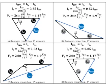
For example, in the case of five-phase machine, three different connections are possible [20]: star, pentagon and pentacle. As the case of three-phase machine, the star connection presents the same amplitudes of inverter and stator currents, and a maximum reachable peak stator voltage close to V = . With five phases, two “polygonal” connections are possible, pentagon by connecting each phase to the adjacent phase (1-to-2, 2-to-3, 3-to-4 …), and pentacle by shifting one phase to connect (1-to-3, 2-to-4, 3-to-5 …).
A five-phase machine can be supplied by different stator sequences (current harmonics), if the connection is “polygonal” (pentagon or pentacle), stator current amplitude depends on the connection and the sequence.
Fig. 1 shows how the stator current amplitude changes in function of the phase connection and the supply sequence. In the case of a five-phase machine, for example, if the current required under the 3rd sequence is more important than the one
under the 1st sequence at a fixed inverter current, the
“pentacle” connection should be chosen. On the other hand, with the pentacle connection, the rated stator voltage is higher under the 1st sequence (adapted to reach high speeds).
Fig. 1. Stator current amplitude for pentagon and pentacle connections under 1st and 3rd sequences.
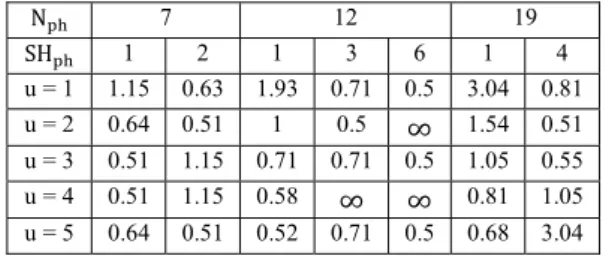
More generally, as described in the Chorus Meshcon patent [18], for a given number of phases N , the number of possible “polygonal” connections is floor . A polygonal connection can be obtained by connecting each stator phase to another phase. The shift between two connected phases, called “SH ”, can be defined as follows:
SH ϵ 1 ⋯ floor (1)
For example, the “pentagon” connection in a five-phase machine corresponds to “SH = 1”, the “pentacle” connection corresponds to “SH = 2”. SH = 2 is the maximum for a five-phase machine according to equation (1). In a multiphase machine with a “polygonal” connection and supplied by a sequence “u” (the stator current sequence), the rated stator current amplitude in function of the amplitude of rated inverter current can be expressed as follows:
I =
. . . (2)
Therefore, the rated stator phase voltage can be defined as follows:
V = 2. sin SH . u. (3)
According to equations (2) and (3), the choice of a “polygonal” connection (parameter “SH ”) and the use of different sequences (parameter “u”) in order to supply the stator of a multiphase machine have an effect of “electrical gearbox” whose ratio can be defined as follows:
EGB =
. . . (4)
If “EGB < 1” the stator current is lower than the inverter current, and the stator voltage is higher than , which is well adapted to the operating points at high speed and low torque (vice versa for “EGB > 1”).
C. Examples and validation using Simplorer
different multiphase connections under different stator sequences. The maximum “EGB ” that can be obtained raises with the phase number (1.15 for 7-phase, 1.93 for 12-phase and 3.04 for 19-12-phase). For high 12-phase numbers, the “electrical gearbox” effect is more important.
In some cases in Table I, “EGB ” is equal to ∞, like the 12-phase connection with “SH = 6” and under even-order stator sequences. In fact, for these cases, the stator voltage V is null, which is a kind of short-circuit induced by the connection under some sequences. Hence, the combinations with “SH . u = N ”, where all stator phases are short-circuited, must be avoided. Thus, for prime phase numbers, like 7 or 19, this kind of short-circuit situation is not possible.
TABLE I
VALUES OF “EGB ” FOR DIFFERENT PHASE CONNECTIONS UNDER
DIFFERENT SUPPLY SEQUENCES.
N 7 12 19 SH 1 2 1 3 6 1 4 u = 1 1.15 0.63 1.93 0.71 0.5 3.04 0.81 u = 2 0.64 0.51 1 0.5 ∞ 1.54 0.51 u = 3 0.51 1.15 0.71 0.71 0.5 1.05 0.55 u = 4 0.51 1.15 0.58 ∞ ∞ 0.81 1.05 u = 5 0.64 0.51 0.52 0.71 0.5 0.68 3.04
The values shown in the Table I are verified using “Simplorer software”. Fig. 2 shows an example of the modeling using this software (all the connections presented in Table I are modeled, only one example of 7-phase is shown).
Fig. 2. 7-phase connection with “SH = 1” modeled by Simplorer
The inverter is controlled by PWM. The sequence used to supply the inverter phases is “u”, so the current in a phase “k” can be expressed in equation (5):
I = I . sin 2π. f . t − k − 1 . u. + φ
(5) As explained above, when the connection is “polygonal”, switching the sequence “u” allows to change the amplitude of stator current and voltage, for the same amplitude of inverter current.
The inverter current, stator current and stator voltage are measured as illustrated in Fig. 2 (Amperemeters for Is and Iinv,
Voltmeter for Vs). The “EGB ” can be obtained by dividing
the value of on the measured fundamental component of stator voltage V , or by dividing the measured fundamental of
stator current I on the fundamental of inverter current I (according to equations (2) and (3)). The calculated values thanks to Simplorer simulations are the same as presented in the Table I.
IV. SPEED RANGE EXTENSION IN NINETEEN-PHASE INDUCTION MACHINE
A nineteen-phase induction machine, for traction application, is sized to operate under three different stator sequences. The connection chosen for this machine is “polygonal” with “SH = 4” (the last column of the Table I), as shown in Fig. 3.
Fig. 3. Polygonal connection with “SHph=4” for the nineteen phase
machine.
In a multiphase machine, operating under different sequences, hence different magnetic pole-pairs numbers [16], the sequences inducing high polarities are usually used for operating region with low speed and high torque. In fact, the high sequences (high polarities) allow a better use of the stator and rotor iron (yokes) which favors the torque density but with an important back-EMF, hence the maximum stator voltage is reached at low speed. Therefore, the low sequences (low polarities) are used for operating region with high speed and low torque.
The “polygonal” connection with “SH = 4” is chosen in order to use the sequences “u=3,4 and 5” in an optimal way. The 5th sequence, naturally favoring high torque with low
speed, has an “EGB ” of 3.04, so the stator current is approximately three times the inverter current, but the maximum stator voltage is low ( ∗ . ), this “EGB ” is well adapted to deliver important torque. The 4th sequence has an
“EGB ” of 1.05, so lower stator current and higher stator voltage than the 5th sequence. The 3rd sequence is used to reach
important speed levels with low torque, thanks to its low polarity and its “EGB ” of 0.55.
This nineteen-phase induction machine with this special phase connection is compared to a three-phase induction machine, regarding operating Torque-Speed characteristic using F-E simulations (Maxwell Software).
A. Three-phase machine
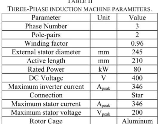
The parameters of the three-phase induction machine, considered as reference for comparison, are listed in the Table II.
TABLE II
THREE-PHASE INDUCTION MACHINE PARAMETERS.
Parameter Unit Value
Phase Number 3
Pole-pairs 2
Winding factor 0.96 External stator diameter mm 245 Active length mm 210 Rated Power kW 80
DC Voltage V 400 Maximum inverter current Apeak 346
Connection Star
Maximum stator current Apeak 346
Maximum stator voltage Vpeak 200
Rotor Cage Aluminum
This machine is simulated by F-E software (Maxwell), by imposing stator current and mechanical speed. The machine geometry with the poles distribution is illustrated in Fig. 4.
Fig. 4. Poles distribution for the three-phase machine
Firstly, the maximum torque developed under the rated stator current (346 Apeak) is determined by sweeping the slip
(difference between the synchronous speed and mechanical speed).
In this kind of simulations, the stator current (amplitude, sequence and frequency) and the mechanical speed (slip) are imposed, so the stator EMF is determined by Maxwell (after achieving the numerical steady state). By increasing the imposed speed, the stator EMF raises. This EMF is limited to the maximum stator voltage (200 Vpeak for this machine), and
this limit corresponds to the base speed. Therefore, to determine the base speed, simulations on different mechanical speed values are done. For each speed value, the stator voltage is determined by Maxwell, and the speed corresponding to the maximum stator voltage of 200 Vpeak is determined by
extrapolation.
TABLE III
BASE SPEED DETERMINATION FOR THE THREE-PHASE INDUCTION MACHINE. Parameter Unit Simulation
1 Simulation 2 Simulation 3 Pole-pairs 2 2 2 Synchronous speed rpm 3000 7000 8000 Mechanical speed rpm 2972 6972 7972 Stator frequency Hz 100 233.33 266.66 Rotor frequency Hz 0.93 0.93 0.93
Inverter current Apeak 346 346 346
Stator current Apeak 346 346 346
Torque N.m 96 96 96
Stator phase voltage
Vpeak 67.4 167.6 193.3
Maximum
stator voltage Vpeak 200
Base speed (extrapolation)
rpm 8230
Fig. 5. Stator phase voltage for the three-phase IM for three different synchronous speeds.
For a given synchronous speed, the slip (so the rotor frequency) that maximizes the torque is found by parametric variation on Maxwell. Then, three simulations are done, to determine the base speed by extrapolation, as shown in Table III. Fig. 5 illustrates the voltage signals for the three operating points (maximum torque with different synchronous speeds).
B. Nineteen-phase machine
The parameters of the nineteen-phase induction machine are listed in the Table IV.
TABLE IV
NINETEEN-PHASE INDUCTION MACHINE PARAMETERS.
Parameter Unit Value
Phase Number 19
Pole-pairs [3, 4, 5] Winding factors under the
used polarities
[0.95 0.99 0.88] External stator diameter mm 255
Active length mm 194 Rated Power kW 80
DC Voltage V 400 Maximum inverter current Apeak 55
Connection Polygonal
(SH = 4) Maximum stator current Apeak [30, 58, 167]
Maximum stator voltage Vpeak [366, 190, 66]
Rotor Cage Aluminum
This machine has the same global volume as the three-phase machine (considering the external stator diameter and active length).
The 19-phase inverter delivers approximately the same apparent power as the three-phase inverter, where:
S = . . I = 103.8 kVA (6)
S = . . I = 104.5 kVA (7)
The chosen winding distribution allows to have important even order space harmonics, so the sequence 4 can be used to supply the machine and with a high winding factor of 0.99. In fact, unlike the three-phase machine, with 19 stator phases the space harmonics are separated into 9 different -planes, so the presence of even order harmonics has a positive effect. In fact, a pole-changing operation with even polarities, like this case of 3-4-5 pole-pairs, is smoother than the case without even sequences. On the other hand, under a given stator sequence the resulting magnetomotive force does not contain
Stator ph
ase vol
harmonics with important amplitudes, for example under the third sequences, the generated space harmonics are 3, 16, 22 … under this sequence the fundamental corresponds to the third space harmonic, and the other harmonics (16, 22 …) have a high order, hence their amplitudes are not important. Fig. 6 shows the machine geometry with poles distribution under the three imposed polarities.
Fig. 6. Poles distribution for the nineteen-phase IM under three polarities (stator sequences)
As seen in the Table IV all of the used sequences (3, 4 and 5) to supply the stator are characterized by important harmonic winding factors, which allow a good torque capability.
This machine is simulated by F-E software (Maxwell), by imposing stator current and mechanical speed, for the three stator sequences “u=3, 4 and 5”.
Firstly, the maximum torques developed under the rated inverter current are determined by sweeping the slip (rotor frequency), for the three supply sequences (thanks to the chosen winding connection, stator current amplitudes are different from a sequence to another, for the same inverter current). Fig. 7 illustrates the maximum torque (with the optimal rotor frequencies) for the nineteen-phase induction machine under the three different polarities (sequences) compared to the three-phase machine maximum torque.
Fig. 7. Comparison of torque between three-phase IM with one polarity, and nineteen-phase IM with three polarities (the winding connection allows different stator current amplitudes for the same maximum inverter current).
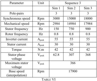
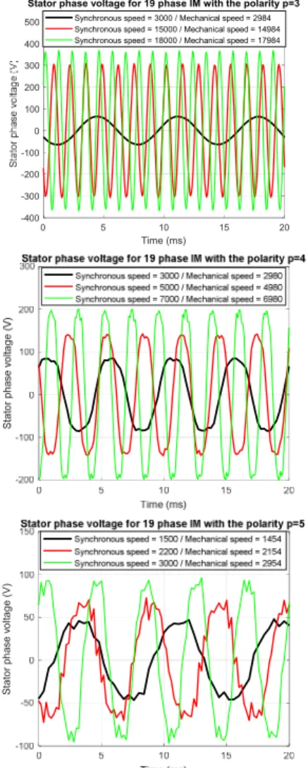
Three simulations were done under each sequence, to determine the base speeds by interpolation, as shown in Table V for the stator sequence “3”, Table VI for the stator sequence “4” and Table VII for the stator sequence “5”. Fig. 8 illustrates the voltage signals under the three polarities, for the three simulations points (synchronous speeds).
Comparing to the three-phase machine, the nineteen-phase machine with its special connection of phases allows to extend the speed range thanks to the use of the third stator supply sequence whose base speed is 18000 rpm, more than two times
the base speed obtained with the three-phase machine. On the other hand, the use of the fifth sequence, where the stator current is amplified thanks to the connection, allows to obtain higher torque at low speed for the same inverter current.
TABLE V
BASE SPEED DETERMINATION FOR THE NINETEEN-PHASE INDUCTION MACHINE –STATOR SEQUENCE 3
Parameter Unit Sequence 3 Sim 1 Sim 2 Sim 3
Pole-pairs 3 3 3
Synchronous speed Rpm 3000 15000 18000 Mechanical speed Rpm 2984 14984 17984
Stator frequency Hz 150 750 900 Rotor frequency Hz 0.8 0.8 0.8
Inverter current Apeak 55 55 55
Stator current Apeak 30 30 30
Torque N.m 42 42 42 Stator phase voltage Vpeak 62.8 307 368 Maximum stator voltage Vpeak 366 Base speed (interpolation) Rpm 17900 TABLE VI
BASE SPEED DETERMINATION FOR THE NINETEEN-PHASE INDUCTION MACHINE –STATOR SEQUENCE 4
Parameter Unit Sequence 4 Sim 1 Sim 2 Sim 3
Pole-pairs 4 4 4
Synchronous speed Rpm 3000 5000 7000 Mechanical speed Rpm 2980 4980 6980
Stator frequency Hz 200 333.33 466.66 Rotor frequency Hz 1.33 1.33 1.33
Inverter current Apeak 55 55 55
Stator current Apeak 58 58 58
Torque N.m 112.5 112.5 112.5 Stator phase voltage Vpeak 79.4 136.5 192.8
Maximum stator voltage Vpeak 190 Base speed (interpolation) Rpm 6895 TABLE VII
BASE SPEED DETERMINATION FOR THE NINETEEN-PHASE INDUCTION MACHINE –STATOR SEQUENCE 5
Parameter Unit Sequence 5 Sim 1 Sim 2 Sim 3 Pole-pairs 5 5 5 Synchronous speed Rpm 3000 2200 1500 Mechanical speed Rpm 2954 2154 1454 Stator frequency Hz 250 183.33 125 Rotor frequency Hz 3.83 3.83 3.83
Inverter current Apeak 55 55 55
Stator current Apeak 167 167 167
Torque N.m 300 300 300 Stator phase voltage Vpeak 89.7 69.2 46.6 Maximum stator voltage Vpeak 66 Base speed (interpolation) Rpm 2049 0 10 20 30 40 50 Time (ms) 0 100 200 300 T orq ue (N. m )
3 phase - p=2 - Stator phase current = 346 Apeak 19 phase - p=3 - Stator phase current = 30 Apeak 19 phase - p=4 - Stator phase current = 58 Apeak 19 phase - p=5 - Stator phase current = 167 Apeak
Fig. 8. Stator phase voltage for the nineteen-phase IM, under the three polarities (three synchronous speeds for each polarity).
The torque-speed characteristics (considering only the constant maximum torque region below the base speed) for both machines (3-phase and 19-phase with the three polarities) are illustrated in Fig. 9. On this figure, the nineteen-phase induction machine with its special connection, and the use of three different stator sequences, presents clearly a very important extension of the torque-speed characteristic comparing to the three-phase machine. The simulated operating points (shown in Table III, Table V, Table VI and Table VII) by Maxwell are marked with red crosses in Fig. 9. The torque and mechanical speed are specified in “p.u” in the figure considering the maximum torque and base speed of the three-phase machine (Table III) as reference.
The torque-speed characteristic, is extended vertically thanks to the use of the fifth stator supplying sequence where the torque can reach 300 N.m (maximum of 96 N.m for the three-phase machine), the values of stator current density (per conductor) are shown in the legend of Fig. 9, with the fifth sequence an important stator current supplies the winding, hence the current density is more important than the other sequences, which requires more sophisticated cooling system. The torque-speed characteristic is also extended horizontally thanks to pole-changing operation. The nineteen-phase machine with its lowest polarity reaches a base speed of 2.2 p.u (considering the base speed of the three-phase IM as a
reference 1 p.u) which represents a very significant enhancement. It must be mentioned that this extension is obtained with almost the same inverter power as the three-phase drive (as shown in the figure 103.8 kVA for the 3-three-phase inverter and 104.5 kVA for the 19-phase inverter).
Fig. 9. Torque-Speed Characteristics comparison between 3-phase induction machine, and 19-phase induction machine supplied by 3 sequences. It should be noted that Fig. 9 does not consider the flux weakening regions (for the 4 characteristics) because the F-E simulations were done only for operating points at maximum torque. Of course, with flux weakening the three-phase induction machine can reach 2 to 3 times the base speed [21]. However, the flux weakening can also be operated for the three polarities in the nineteen-phase machine, which can allow to provide constant power curves between the maximum power points for each polarity. Under the lowest polarity of the 19-phase IM (p = 3), which have an important base speed, the flux weakening operation can be operated to reach very high speeds (unreachable with the three-phase machine).
V. CONCLUSION
In this paper, the effect of stator sequence switching with specific phase connections on the stator current and voltage has been investigated. A mathematical representation of the stator connection has been provided and it allows to determine the amplitudes of stator current and voltage for a given inverter current and DC voltage.
An application on a nineteen-phase induction machine with a special stator phase connection allowing to extend the torque-speed characteristic has been presented. Thanks to Finite-Element approach, the torque-speed characteristic of this machine with pole-changing operation has been estimated and compared with a three-phase induction machine with the same global volume and the same inverter power.
The results show a very significant extension of the torque-speed characteristic vertically (improvement of torque density) and horizontally (improvement of speed range), thanks to the pole-changing operation and the chosen phase connection for the nineteen-phase induction machine.
This extension is obtained with the same machine volume as the three-phase machine, thanks to a better use of the machine iron with the multipolarity operation, and with the same inverter power thanks to the “electrical gearbox” effect presented in this paper, so there is no need to oversize the inverter components in order to reach more important torque (obtained here with the sequence “5”). Of course, even if this high torque is obtained with the same inverter current, the
0 5 10 15 20 Time (ms) -400 -300 -200 -100 0 100 200 300 400 500
Stator phase voltage for 19 phase IM with the polarity p=3
Synchronous speed = 3000 / Mechanical speed = 2984 Synchronous speed = 15000 / Mechanical speed = 14984 Synchronous speed = 18000 / Mechanical speed = 17984
S tat or pha se v o ltage (V )
stator current density is higher than the other sequences, so the cooling system must be adapted.
This torque speed-characteristic improvement is obtained with a fixed stator phase connection, so without dedicated switches to change physically the machine coupling and which increase the complexity of the drive.
VI. REFERENCES
[1] A. S. Abdel-khalik, S. M. Gadoue, M. I. Masoud, and B. W. Wiliams, “Optimum Flux Distribution With Harmonic Injection for a Multiphase Induction Machine Using Genetic Algorithms,”
IEEE Trans. Energy Convers., vol. 26, no. 2, pp. 501–512, 2011,
doi: 10.1109/TEC.2010.2093139.
[2] M. Mengoni, L. Zarri, A. Tani, L. Parsa, G. Serra, and D. Casadei, “High-torque-density control of multiphase induction motor drives operating over a wide speed range,” IEEE Trans. Ind. Electron., vol. 62, no. 2, pp. 814–825, 2015, doi:
10.1109/TIE.2014.2334662.
[3] L. A. Pereira, Sérgio Haffner, L. F. A. Pereira, and R. S. da Rosa, “Torque Capability of High Phase Induction Machines with Sinusoidal and Trapezoidal Airgap Field under Steady State,” in
IECON, 2013, pp. 3183–3188, doi:
10.1109/IECON.2013.6699637.
[4] W. Kong, J. Huang, R. Qu, M. Kang, and J. Yang, “Nonsinusoidal Power Supply Analysis for Concentrated-Full-Pitch-Winding Multiphase Induction Motor,” IEEE Trans. Ind. Electron., vol. 63, no. 1, pp. 574–582, 2016.
[5] A. Patzak, F. Bachheibl, A. Baumgardt, G. Dajaku, O. Moros, and D. Gerling, “ISCAD - Electric High Performance Drive for Individual Mobility at Extra-Low Voltages,” SAE Int. J. Altern.
Powertrains, vol. 5, no. 1, pp. 2016-01–1179, 2016, doi:
10.4271/2016-01-1179.
[6] Y. Jia-qiang, H. Hao-feng, and H. Jin, “Electronic pole changing technique of multiphase induction motor based on vector control,”
Eur. Trans. Electr. POWER Euro., vol. 23, no. 7, pp. 901–913,
2012, doi: 10.1002/etep.
[7] E. Libbos, B. Ku, S. Agrawal, S. Tungare, A. Banerjee, and P. T. Krein, “Variable-Pole Induction Machine Drive for Electric Vehicles,” in IEEE International Electric Machines & Drives
Conference (IEMDC), 2019, pp. 515–522.
[8] B. Ge, D. Sun, W. Wu, and F. Z. Peng, “Winding Design, Modeling, and Control for Pole-Phase Modulation Induction Motors,” IEEE Trans. Magn., vol. 49, no. 2, pp. 898–911, 2013. [9] B. P. Reddy, B. S. Umesh, A. M. Rao, B. V. R. Kumar, and K. S.
Kumar, “A five speed 45-phase induction motor drive with pole phase modulation for electric vehicles,” in 2017 IEEE
International Conference on Industrial Technology (ICIT), Toronto, ON, 2017, pp. 258–263, doi:
10.1109/ICIT.2017.7913093.
[10] G. Dajaku and D. Gerling, “Opportunities of advanced multi-phase concentrated windings,” Proc. - 2018 23rd Int. Conf. Electr.
Mach. ICEM 2018, vol. 1, no. 1, pp. 325–331, 2018, doi:
10.1109/ICELMACH.2018.8506932.
[11] E. Levi, D. Dujic, M. Jones, and G. Grandi, “Analytical determination of DC-bus utilization limits in multiphase VSI supplied AC drives,” IEEE Trans. Energy Convers., vol. 23, no. 2, pp. 433–443, 2008, doi: 10.1109/TEC.2008.921557.
[12] M. Vujacic, O. Dordevic, and G. Grandi, “Evaluation of DC-Link Voltage Switching Ripple in Multiphase PWM Voltage Source Inverters,” IEEE Trans. Power Electron., vol. 35, no. 4, pp. 3478– 3490, 2020, doi: 10.1109/TPEL.2019.2936429.
[13] N. Kesbia, J. L. Schanen, L. Garbuio, and M. Ameziani, “Impact of the number of phases on losses of a multiphase inverter for electric vehicle drive,” 2019 10th Int. Power Electron. Drive Syst.
Technol. Conf. PEDSTC 2019, no. 1, pp. 589–594, 2019, doi:
10.1109/PEDSTC.2019.8697524.
[14] H. R. Fudeh and C. M. Ong, “Modeling and analysis of induction machines containing space harmonics: Part I: Modeling and
Transformation,” IEEE Trans. Power Appar. Syst., vol. PAS-102, no. 8, pp. 2608–2615, 1983, doi: 10.1109/TPAS.1983.317781. [15] A. Mekahlia, E. Semail, F. Scuiller, and H. Zahr, “Reduced-Order
Model of Rotor Cage in Multiphase Induction Machines : Application on the Prediction of Torque Pulsations,” Math.
Comput. Appl., vol. 25, no. 11, 2020.
[16] A. Mekahlia, E. Semail, F. Scuiller, and H. Zahr, “Impact of Winding Parameters on Torque Level under Harmonic Injection in Multiphase Induction Machine,” in IECON 2019 - 45th Annual
Conference of the IEEE Industrial Electronics Society, 2019, pp.
6217–6222, doi: 10.1109/iecon.2019.8927108.
[17] M. Osama and T. A. Lipo, “A new inverter control scheme for induction motor drives requiring wide speed range,” IEEE Trans.
Ind. Appl., vol. 32, no. 4, pp. 938–944, 1996, doi:
10.1109/28.511652.
[18] J. S. Edelson, “High phase order ac machine with short pitch winding,” UK Patent 2 430 086, Jan.30, 2008.
[19] J. S. Edelson, I. W. Cox, and J. S. Magdych, “The Chorus Meshcon solution for starter-generators,” in IEEE International
Conference on Electric Machines and Drives, 2005, pp. 1720–
1724, doi: 10.1109/iemdc.2005.195952.
[20] S. Sadeghi, L. Guo, H. A. Toliyat, and L. Parsa, “Wide operational speed range of five-phase permanent magnet machines by using different stator winding configurations,” IEEE Trans. Ind.
Electron., vol. 59, no. 6, pp. 2621–2631, 2012, doi:
10.1109/TIE.2011.2164771.
[21] E. F. Fuchs, J. Schraud, and F. S. Fuchs, “Analysis of critical-speed increase of induction machines via winding reconfiguration with solid-state switches,” IEEE Trans. Energy Convers., vol. 23, no. 3, pp. 774–780, 2008, doi: 10.1109/TEC.2008.921478.
VII. BIOGRAPHIES
Abdelhak Mekahlia was born in Annaba, Algeria, on April 19, 1991. He
obtained his engineer degree from the ENP “Ecole Nationale Polytechnique”, Algiers, and a Master degree from ParisTech, France. His employment experience included Akka Technologies Company and Vedecom institute in France. His special fields of interest included electrical machines and control strategies. Actually he is preparing his Ph.D degree at ENSAM School “Arts et Metiers ParisTech”, L2EP Laboratory “Laboratoire d’Electrotechnique et d’Electronique de Puissance” and Vedecom institute, France.
Eric Semailgraduated in 1986 from the Ecole Normale Supérieure, in France. He received Ph.D. degree in 2000. He became full Professor in 2010 at Engineering school of ARTS et METIERS Institute of Technology. In Laboratory of Electrical Engineering of Lille (L2EP) in France, his fields of interest include design, modeling and control of multi-phase electrical drives (converters and AC Drives). More generally, he studies, Multi-machine and Multi-converter systems. Fault Tolerance for electromechanical conversion at variable speed is one of the applications of the research with industrial partners in fields such as automotive, marine and aerospace.
Franck Scuiller received the Electrical Engineering degree (M.Sc. degree) from
ENSIEG, INPG (Grenoble National Polytechnic Institute) in 2001 and the Ph.D. Degree from “Arts et Métiers ParisTech” in 2006. In 2007, he was a lecturer in French Naval Academy. From 2008 to 2011, he was a technical project manager in warship electric power systems for DCNS Company (Lorient, France). Since September 2011, he is an Associate Professor in Electrical Engineering in the French Naval Academy. His research interest is multi-phase machines for marine applications (ship propulsion, marine current turbine).
Hussein Zahr received the B.S. and M.S. degrees from the Faculty of
engineering, Lebanese university and Ecole Polytechnique de Nantes in 2013, and the Ph.D. degree from the École Nationale Supérieure des Arts et Metiers in 2016. He is currently researcher in Vedecom Institute. His main research interests include design, modeling, and control of multiphase machines for variable speed applications.