Application of a bi-level scheme including topology
optimization to the design of an aircraft pylon
1A. Remouchamps1, M. Bruyneel1, C. Fleury2, S. Grihon3
1SAMTECH, Liège Science Park, Rue des Chasseurs-ardennais 8, Angleur, B-4031, Belgium
2Aerospace & Mechanical Deparetment , University of Liège, Chemin des Chevreuils 1,Liège, B-4200, Belgium
3Airbus, Route de Bayonne 316, 31060 Toulouse, France
Abstract
In this paper, topology optimization is used to design aircraft pylons. Original results for two Airbus pylons are first presented. An innovative bi-level optimization scheme is then proposed, which combines topology and geometric optimizations. At the first level, the dimension of the design domain, that is the envelope of the structure, and the location of the fixations are variables. At the second level, topology optimization is used to determine the optimal lay-out for given geometric parameters. This bi-level scheme is used to solve the aero-structural optimization of a pylon.
Keywords: topology optimization, multidisciplinary optimization, bi-level optimization, industrial application
1. Introduction
Since the pioneering work of Bendsoe and Kikuchi (1988), and Bendsoe (1989), topology optimization has been the subject of much research (Bendsoe and Sigmund, 2003). It is now a mature design methodology used at industrial levels, for instance in aeronautical applications (see e.g. Krog et al., 2004; Bendsoe and Stolpe, 2008; Saleem et al., 2008; Saleem and Yuqing, 2010).
When considering an aircraft component such as the pylon, both structural requirements (stiffness and weight) and aerodynamic concerns (drag) should be taken into account in the design phase. The use of multidisciplinary optimization is recommended in these situations. Multidisciplinary optimization has been studied for a long time. It has found many applications in aeronautics, where aerodynamic and structural requirements are essential (Sobieszczanski and Haftka, 1997). Amongst many others, Gundlach et al. (2000) proposed a multidisciplinary optimization scheme for the design of a strut-braced wing, where not only the shape of the wing is optimized, but also the geometry of the strut with respect to stiffness, weight and drag requirements; in Zhang et al. (2008), the wing geometry and its internal arrangement (location of the spars) are optimized in order to maximize the lift-to-drag ratio while limiting the maximum stress and deformation; in Santer and Pelligrino (2009), topology optimization is
wing leading edge, which deforms in a way prescribed by aerodynamic constraints, while sustaining the corresponding pressure.
In this paper, topology optimization is used in a bi-level scheme in order to design a pylon with respect to structural and aerodynamic requirements.
Initially, original results obtained in the conceptual design phase of Airbus engine pylons are presented. Topology optimization is used to determine the optimal layout of these structures, which are submitted to several static load cases. In the optimization problem, the structural stiffness is maximized and constraints on the volume and on some displacements are taken into account. The SIMP formulation is used, and the continuous design variables are the pseudo-densities defined in each finite element (Bendsoe and Sigmund, 2003). These variables take values that vary continuously between 0 and 1 to represent void and solid at the solution. Two different initial design concepts of the pylon are studied. The influence of some optimization parameters on the results obtained is illustrated. Then, a bi-level optimization scheme is proposed. Since the boundary conditions and the surrounding envelope, i.e. the dimensions of the design domain, may strongly influence the resulting optimal topology, a strategy is developed to parameterize the problem with respect to these parameters, which are referred to as the global geometric design variables. Two distinct sets of design variables are then defined: the first level includes the global geometric parameters, and the second level variables are the pseudo-densities used for the topology optimization problems. The principle of this bi-level optimization scheme is described using a simple application including only structural requirements. Bi-level optimization schemes have already been developed and used in the literature (see for example BLISS developed by Sobieszczanski-Sobieski et al., 1998, and Sobieszczanski-Sobieski and Kodiyalam, 2001). In contrast to that scheme, the bi-level method developed in this paper does not carry out local optimizations on substructures of an entire structure (i.e. the concept of decomposition), neither does it rely on derivatives to relate both global and local optimizations.
Finally, the bi-level optimization scheme is used to design a pylon with respect to structural (weight and stiffness) and aerodynamic (drag) requirements. Topology optimization is used to identify structures of minimum weight which satisfy some constraints on displacements, for different values of the global geometric design variables. Drag is calculated based on the same values of the geometric design variables. These aerodynamic and structural responses feed a cost function, which is minimized using a surrogate-based optimization method that ultimately provides the optimal values of the geometric design variables and identifies the best structural lay-out of the pylon.
In the present study, there is no special attention paid to the design of the fasteners themselves. It is clear (see for instance Chickermane et al., 1999) that for practical applications stress-based criteria and possibly fracture mechanics considerations should be taken into account for the design of these important connections.
2. Topology optimization with the TOPOL software
Topology optimization is a very general tool available from structural optimization techniques (Bendsoe and Sigmund, 2003) available in the SAMCEF environment (Remouchamps et al., 2007). It is used to determine the optimal layout of the structure, that is the optimal distribution of the mechanical properties in a prescribed design domain for a given amount of material. The classical formulation of a topology optimization problem (1) consists in maximizing thestiffness of the structure for a given volume fraction of the material required at the solution. In the static case, the compliance C is minimized over the nc load cases, while for the dynamic case the nf first natural frequencies computed with a modal analysis are maximized. Constraints on nodal displacements can also be taken into account via virtual load cases (vlc). In this problem, the n design variables are the pseudo-densities attached to each finite element of the model.
l T l l nc l C g q μ ,1 max
min nc load cases (linear static analysis)
subject to: Kql gl
m T
m
m u
u b q m = 1,…,vlc (virtual load cases)
k nf k 1, min max μ
nf eigen-frequencies (modal analysis) subject to:
Kk2M
qk 0 with V V i i i 1 0 i i
i,i1,...,n
μ (1)In the set of equations (1), glare the vectors of nodal loads for each load case l, K is the stiffness matrix of the finite element model and ql are the corresponding
nodal displacements; M is the mass matrix, k the natural frequencies and qk the
related vibration modes; b is a vector used for the localization of the degrees of freedom in the displacement vector q (Arora and Haug, 1979) ;u is the upper bound on the displacement ; V is the available amount of material to be distributed in the design domain and Vi is the volume of element i. u is a flexibility constraint: it is a combination of some degrees of freedom used for the definition of constraints on nodal displacements. These constraints are treated as virtual load cases (vlc). In TOPOL, the SIMP material law is used (Bendsoe and Sigmund, 2003), and the material parameterization is given in (2), where 0 and EOare the base material properties, andivaries continuously in ]0,1].
0 i i 0 E Ei ip (2)
The exponent p in (2) is larger than 1 to penalize the intermediate densities at the solution. In topology optimization, a design variable may be attached to each finite element of the model and the solution is obtained for a fixed mesh. At the element stiffness level, applying the parameterization (2) leads to the relation (3). It is the case that the element stiffness Ki, independent of the design variable i,
is computed only once (i.e. at iteration 0) and may be re-used for the following iterations of the optimization process. The elements are then generated only once,
In TOPOL, the body loads can be included in the optimization problem. These loads vary with the values of the design variables, as expressed by equation (4), where g is independent of the design variable.i
i i
i g
g (4)
For the sake of brevity, the details of the sensitivity analysis are not provided, but it is noted that the adjoint method is used (Remouchamps et al., 2007). In order to avoid the numerical instabilities that may appear during the solution procedure (checkerboard patterns, dependency of the solution with the mesh size), a filtering technique is used (Sigmund and Peterson, 1998).
Depending on the functions defined by the user, different problem statements are considered in TOPOL. When only the compliances are taken into account in the design problem, these functions are minimized in a multi-objective formulation with respect to a constraint on the target volume fraction. When constraints on the displacements are the only stiffness functions of the problem, the weight is minimized with respect to these constraints. When both compliances and displacements are considered, the displacements and the target volume fraction become the constraints of the problem and the compliances are minimized.
Topology optimization is a large scale problem in terms of design variables. However, the formulation includes few design functions, the number of which depends on the number of load cases considered in the static analysis (compliances), the number of vibration frequencies to maximize and the number of constrained nodal displacements in (1). Specific gradient-based optimization methods relying on the sequential convex programming and on the dual approach proved to be reliable (from a CPU point of view) for the solution of optimization problems involving several millions of design variables and a small number of functions, say around 100 functions (Fleury, 2009). Here the Conlin approximation (Fleury and Braibant, 1986) is used in conjunction with efficient dual solvers (Fleury, 1993) in a multi-objective formulation. The GCM approximation (Bruyneel et al., 2002) is also available in TOPOL for problems including body forces and presenting non-monotonous behaviors (Bruyneel and Duysinx, 2005; Bruyneel, 2006).
3. Optimal topologies of Airbus pylons
In this section, topology optimization is applied to the design of Airbus pylons (Figure 1). Two different pylon design concepts are studied. The models are meshed with first order tetrahedral elements. The SAMCEF finite element code is used to solve the linear static analyses. Even if the tetrahedral mesh is non symmetric with respect to the main pylon direction, symmetry is taken into account in the optimization problem due to a specific means of linking of the design variables.
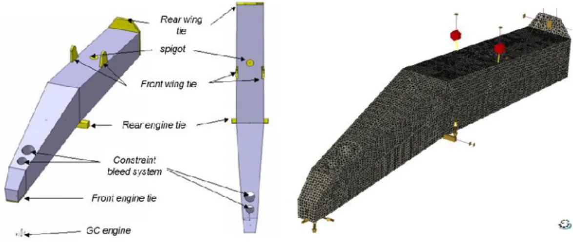
Fig 1. The aircraft pylon to be designed with topology optimization
3.1 Initial concept
The geometry of the first design domain is illustrated in Figure 2, together with the devices for the pylon/engine and pylon/wing attachments. The gravity center of the engine is also located. The mesh includes 244021 first order tetrahedral elements. One pseudo-density design variable is associated with each volume element. The pylon is submitted to 8 static load cases (lc = 8), corresponding to maneuvers, gust, fan blade off and "landing on the engine" scenarios. The displacements of the gravity center of the engine are also restricted in two directions (vlc = 2). The volume constraint is set to 10% of the initial volume of Figure 2. Several problem statements given in (1) are tested, for the linear static analysis: minimization of the compliance with a constraint on the volume, minimization of the volume with constraints on the displacements, and minimization of the compliances with constraints on the volume and on the displacements. Figures 3 to 4 provide the results obtained after 20 iterations, for two values of the penalty factor in the SIMP law (2). Only the elements with a pseudo-density larger than 0.5 are shown. It is observed that when the constraints on the displacements are taken into account, more complex topologies are obtained. The iteration history is illustrated in Figure 5.
Fig 3. a) Result for the 8 load cases (lc = 8), with p = 2; b) Result for the constraints on the displacements (vlc = 2) with p = 2
Fig 4. a) Result for all the load cases and all the constraints (volume and displacements) with p = 2 (lc = 8 and vlc = 2);
b) Result for all the load cases and all the constraints (volume and displacements) with p = 4 (lc = 8 and vlc = 2)
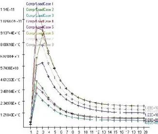
Fig 5. Iteration history for the first design
3.2 Alternative design concept
The geometry of the alternative design domain is illustrated in Figure 6, together with the devices for the pylon/engine and pylon/wing attachments. The model includes 420839 first order tetrahedral elements. One pseudo-density design
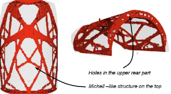
variable is associated with each volume element. As was the case with the first design, the pylon is submitted to 8 static load cases (lc = 8), corresponding to maneuvers, gust, fan blade off and "landing on the engine" scenarios. The displacements of the gravity center of the engine are also restricted in two directions (vlc = 2). The volume constraint is set to 10% of the initial volume. Several problem statements given in (1) are tested, for the linear static analysis: minimization of the compliance with a constraint on the volume, minimization of the volume with constraints on the displacements, and minimization of the compliances with constraints on the volume and on the displacements. The results are provided in Figures 7 and 8, for two values of the penalty factor in the SIMP law (2). In these results, only the elements with a pseudo-density larger than 0.4 are shown. The solutions shown in Figures 7 and 8 are obtained in about 40 iterations. In Figure 9, two details of the solution are highlighted. It is clearly observed that a usual optimal topology for a Michell-like structure (Michell 1904, Bendsoe and Sigmund 2003) appears on the top of the optimal design, and that holes are created in the upper rear part.
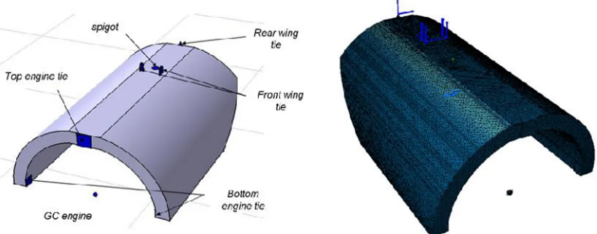
Fig 6. Geometry of the alternative design concept and finite element mesh
Fig 7. a) Result for the 8 load cases (lc = 8) with p = 3;
Fig 8. a) Result for all the load cases and all the constraints (volume and displacements) with p = 3 (lc = 8 and vlc = 2);
b) Result for all the load cases and all the constraints (volume and displacements) with p = 4 (lc = 8 and vlc = 2)
Fig 9. Details of the solution presented in Figure 8b
4. The bi-level optimization scheme
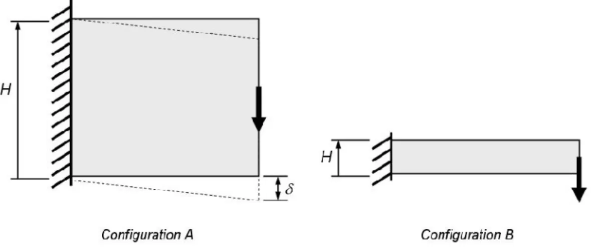
Based on the previous application, it is evident that the optimal topology and, consequent mechanical performances (stiffness and weight) will depend strongly on the size and dimensions of the design domain where the material must be distributed. Moreover, the definition of the boundary conditions and the location of the loads can also have an impact on the resulting optimal topology. This is discussed in the simple application shown in Figure 10, in the case of a modification in the dimensions of the design domain. The goal here is to determine the optimal topology of a structure that is clamped on one edge and submitted to a given load in the middle of the opposite edge. The weight is minimized with a constraint on the vertical displacement of the emerging structure along the load direction. Depending on the value prescribed to the maximum allowable displacement, different solutions of minimum weight can be identified. When the maximum allowable displacement is small, the structure must be very
stiff, and the height H of the design domain must therefore be large. The optimal topology for minimum weight, for this large design domain, may present a large weight (configuration A of Figure 10). On the contrary, when the maximum allowable displacement is larger, the final weight can be decreased by working with a smaller value of H (configuration B of Figure 10). In practice, for a given value of the maximum allowable displacement, an intermediate value of H must be determined in order to provide the lightest structure satisfying the constraint on the displacement.
Fig 10. Test case for the demonstration of the bi-level scheme
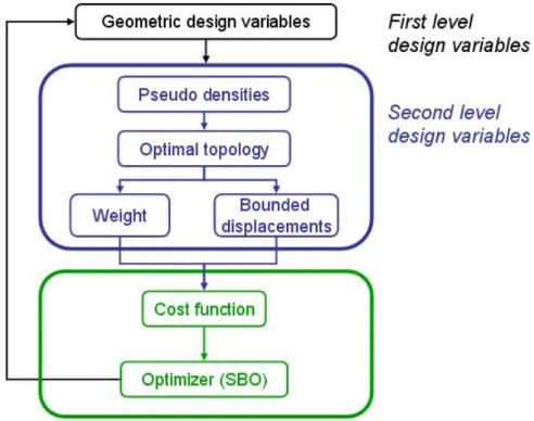
As a consequence, in order to identify a solution to the problem shown in Figure 10, for a given maximum allowable displacement, both topology and geometric optimizations must be considered, the first one working with pseudo-densities design variables, and the second one relying on geometric parameters (H in this case). A simple way to take these two distinct sets of design variables into account is presented in Figure 11. In the bi-level optimization scheme proposed in this paper, the two sets of design variables are separated. At the first level, the geometric design variables take different values providing different sizes of the design domain. At the second level, topology optimization is used to identify the optimal structures of minimum weight W, that best satisfy the constraint on the displacement
H , for the given design domain. Some of these optimal topologies may provide unfeasible solutions. These can be penalized in the definition of the cost function (5), which is minimized with respect to the geometric design variables with a surrogate-based method (for example).Fig 11. Principle of the bi-level optimization scheme
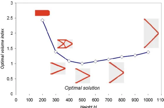
W(H) 1000 max0; (H) Cost (5)The principle of the bi-level scheme presented in Figure 11 is now demonstrated on the application shown in Figure 10. Here, a parametric study is conducted on the value of the geometric parameter H, and the resulting optimal topologies are reported in Figure 12, for a given value of the maximum allowable displacement. It is seen that a specific value of the height H provides the lightest optimal structure. A change of topology is observed when the size of this domain changes. Similar conclusions can be drawn when the location of the fixations are changed in the model.
Fig 12. Principle of the bi-level scheme explained with the test problem
5. The multidisciplinary bi-level optimization
scheme
5.1 Principle of the bi-level multidisciplinary optimization scheme
The bi-level scheme with its two sets of design variables, is now applied to the multidisciplinary optimization of the pylon of Figure 2, with aerodynamic and structural requirements. The drag depends on the dimensions of the pylon’s envelope and is independent of the internal topology, which is a structural concern involving mass and stiffness. However, as explained earlier on a simple example, the resulting mass and stiffness depend on the global geometric design variables, i.e. the dimensions of the design domain and the location of the fixations.
Two optimization problems are identified. The first one concerns the identification of the optimal topology of the pylon, for fixed geometry and boundary conditions, leading to a structure of minimum weight and requested stiffness, with local pseudo-density design variables (Figure 13). The second problem impacts the global geometric design variables associated with the dimensions and the boundary conditions. It consists in the minimization of the drag and the structural weight with respect to these variables (Figure 14). The requirements are conflicting: the design domain needs to be sufficiently large in order to provide a structure with a correct stiffness, while the drag is penalized by a design envelope that is too large. The successive values of the global geometric design variables are managed by a surrogate-based optimization method, which
Fig 13. For a given geometry, what is the optimal topology with minimal weight?
Figure 14. What is the optimal surrounding geometry, with respect to aerodynamics and weight requirements ?
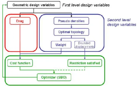
The resulting bi-level multidisciplinary optimization scheme is illustrated in Figure 15. The first level design variables impact the drag and the resulting optimal topology, since this last depends on the dimension of the design domain and the location of the fixations. The second level design variables determine the optimal lay-out for given values of the global design variables. The cost function is fed with the weight and drag responses. A surrogate-based method manages the successive values of the global geometric design variables towards their optimum.
Fig 15. Principle of the bi-level multidisciplinary optimization scheme
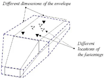
5.2 Global geometric design variables and aerodynamics calculation
CFD (Computational Fluid Dynamics), which has a significant effect on the computational time, is not used in this paper. A simpler approach is preferred, since it is sufficient to demonstrate the applicability of the bi-level optimization scheme. The drag D is calculated with the following basic equations, involving the global geometric design variables illustrated in Figure 16:
S C v D x 2 2 (5) with mid w mid h front w front h Cx _ _ _ _ 1 . 0 6 10 _ _ h back w back S 220 v
These global design variables define the position of the fixations between the pylon and the wing, and the pylon and the engine, as well as the overall dimensions of the pylon envelope.
5.3 Application to the aero-structural design of the pylon
The model of Figure 16 includes 17848 finite elements. This mesh density is sufficient to interpret the resulting topologies. For topology optimization, the SIMP law is used with a penalty of 3.5. Considering the imposed symmetry of the solution and the elements with a density prescribed to 1, the problem involves 8568 pseudo-density design variables. The bi-level optimization problem is defined in the BOSS Quattro environment (Radovcic and Remouchamps, 2002), as illustrated in Figure 17. For the global optimization process acting on the global geometric design variables, a surrogate based method is used (Colson et al., 2010). A data base is constructed based on the values of the computed drag and on the structural weight obtained with topology optimization. A cost function is built, and a global response surface is generated with a neural network. A genetic algorithm is then used to obtain the minimum of the global approximation. New analyses are conducted around the identified optimum, and a new response surface is built. The process continues and modifies the values of the global geometric design variables until the desired convergence criterion is satisfied. For the topology optimization, the procedure described in the previous sections is applied. For each set of global geometric parameters, the optimal topology for minimum weight is identified with satisfied constraints on some displacements. This provides the structural mass feeding the cost function.
The bi-level optimization problem can be summarized as follows: ) ( ) ( min x x x W D s.t. W V μ min , for given x m m u u (μ) , m1,2 (6)
where x is the set of global geometric design variables, D is the drag, W is the minimum structural weight for given values of x, and u are the displacements of
the engine’s gravity center. and are two scaling factors. The information on
the cost function is collected in an EXCEL sheet, which is used by the surrogate-based optimization method. The results are provided in Figures 18 to 20, and the optimal values of the geometric design variables can be found in Table 1. The optimal design is presumed to be obtained when the relative variation of the global geometric design variables becomes less than 0.01%. It is observed in Table 1 that most of the design variables reach either their minimum or their maximum bound value. Using more realistic bounds on the design variables would certainly provide another result. The reader will appreciate that for confidentiality reasons, these more realistic results are not revealed here. In the surrogate-based method method (Colson et al., 2010), a response surface relying on neural networks is first determined, based on a set of available (computed) function values. The optimization is then carried out on these approximated functions, with a genetic algorithm. The intermediate optimal solution, and some other candidate points, are used to enrich the data base, and a new response surface is built. This process goes on until final convergence. The iteration history observed in Figures 18 and 19 is typical of a surrogate-based method, with a large period of oscillations corresponding to the selection of new points for the data base used for the response surface. A damping of these oscillations is observed here after 110 iterations, and the solution is obtained after 133 cycles, that is 133
runs of the topology optimization tool. This represent 2660 finite element analyses since a fixed number of 20 iterations are used for each topology optimization run. Figure 20 illustrates the initial and optimal topologies, and the corresponding modifications observed in the overall geometry of the pylon, due to structural and aerodynamic requirements. A gain of 57% in the drag is observed, for an increase of 3% in the structural weight.
Fig 17. Definition of the bi-level optimization problem in BOSS Quattro
Fig 18. Evolution of the cost function and of the engine GC in the Z direction, during the surrogate-based optimization
Fig 19. Evolution of four design variables during the iterative process
Fig 20. Initial and optimal topologies
Name Minimum value Initial value Optimal value Maximum value
H_Front 100 100 100 150 W_Front 200 200 200 300 H_Mid 400 700 700 700 W_Mid 500 750 669.5 750 H_Back 400 700 400 700 W_Back 500 800 500 800 L_Mid2Frontfix 500 1100 1200 1200 L_Mid2Spigot 1247 1500 1247 2000
6. Conclusions
In this paper, original results obtained in the topology optimization of two Airbus pylons have been presented. An innovative bi-level optimization scheme was then proposed to design a pylon with respect to aerodynamics (drag) and structural (mass, stiffness) requirements. At the first optimization level, a surrogate based optimization method is used to minimize the drag and the weight. The design variables impacted at that level are global geometric parameters (position of the fixations and dimensions of the design domain). At the second level, a topology optimization problem is solved, in order to obtain the optimal weight, used in the first level, with constraints on some displacements. The developed strategy is demonstrated in the aero-structural design of an Airbus pylon.
Acknowledgements
A part of the development of the bi-level optimization approach has been performed within the CRESCENDO project, funded by the European Community’s Seventh Framework Program (FP7/2007-2013) under grant agreement n◦ 234344 (www.crescendofp7.eu/).
References
1. Arora J.S. and Haug E.J. (1979). Methods of design sensitivity analysis in structural optimization. AIAA Journal, 17(9): 970-974.
2. Bendsoe M.P. and Kikuchi N. (1988). Generating optimal topologies in structural design using a homogenization method. Computational Methods in Applied Mechanics and Engineering, 71: 197–224.
3. Bendsoe M.P. (1989). Optimal shape design as a material distribution problem. Structural Optimization, 1: 193-202.
4. Bendsoe M.P. and Sigmund O. (2003). Topology optimization: theory, methods and applications, Springer, Berlin Heidelberg New York.
5. Bendsoe M.P. and Stolpe M. (2008). PLATO-N: developing specialized methods for aeronautics structural design applications. International Conference on Engineering Optimization, 1-5 June 2008, Rio de Janeiro, Brazil.
6. BOSS Quattro. www.samtech.com
7. Bruyneel M. and Duysinx P. (2005). Note on topology optimization of continuum structures including self-weight, Structural & Multidisciplinary Optimization, 29: 245-256.
8. Bruyneel M., Duysinx P. and Fleury C. (2002). A family of MMA approximations for structural optimization, Structural & Multidisciplinary Optimization, 24: 263-276.
9. Bruyneel M. (2006). A general and effective approach for the optimal design of fiber reinforced composite structures, Composites Science & Technology, 66: 1303-1314.
10. Chickermane H., Gea H.C., Yang R.J. and Chuang C.H. (1999). Optimal fastener pattern design considering bearing loads. Structural Optimization, 17, pp. 140-146.
11. Colson B., Bruyneel M., Grihon S., Raick C. and Remouchamps A. (2010). Optimization methods for advanced design of aircraft panels: a comparison, Optimization & Engineering, 11(4), pp. 583-596.
12. Fleury C. (1993). Sequential convex programming for structural optimization problems, in: Optimization of large Structural Systems: Proceedings NATO/DFG Advanced Study Institute, 1:
15. Gundlach J.F., Tétrault P.A., Gern F., Nagshineh A., Ko A., Schetz J.A., Mason W.H., Kapania R., Grossman B., Haftka R.T. (2000). Multidisciplinary design optimization of a strut-braced wing transonic transport, 38th Aerospace Sciences Meeting and Exhibit, 10-13 January
2000, Reno, Nevada. AIAA 2000-0420.
16. Krog L., Tucker A., Kemp M. and Boyd R. Topology optimization of aircraft wing box ribs. Proc. of the 10th AIAA/ISSMO MAO Conference, 2004, Albany
17. Michell A.G.M. (1904). The limits of economy of material in frame structures. Philosophical Magazine, s.6., 8(47): 589-597.
18. Radovcic Y. and Remouchamps A. (2002). BOSS Quattro: an open system for parametric design, Structural & Multidisciplinary Optimization, 23: 140-152.
19. Remouchamps A., Grihon S., Colson B., Raick C. and Bruyneel M. (2007). Numerical optimization: a design space odyssey, 1st International Conference on Advancements in Design Optimization of Materials, Structures and Mechanical Systems, December 17-20, 2007, Xi’an, China.
20. Saleem W., Yuqing F. and Yunqiao W. (2008). Application of topology optimization and manufacturing simulations – A new trend in design of aircraft components. International MultiConference of Engineers and Computers Scientists, 19-21 March 2008, Hong Kong.
21. Saleem W. and Yuqing F. (2010). Stragegy for optimal configuration design of existing structures by topology and shape optimization tools. International Journal of Aerospace and Mechanical Engineering, 4, pp. 226-234.
22. SAMCEF. www.samtech.com
23. Santer M. and Pelligrino S. (2009). Topological optimization of compliant adaptive wing structure. AIAA Journal, 47(3), pp. 523-534.
24. Sigmund O. and Peterson J. (1998). Numerical instabilities in topology optimization: a survey on procedures dealing with checkerboards, mesh-dependencies and local minima, Structural Optimization, 16: 68-75.
25. Sobieszczanski J. and Haftka R.T. (1997). Multidisciplinary aerospace design optimization: survey of recent developments, Structural Optimization, 14: 1-23.
26. Sobieszczanski-Sobieski J., Agte J., Sandusky J.R. (1998). Bi-level integrated system synthesis (BLISS). Proc. 7th AIAA/USAF/NASA/ISSMO Symp. On Multidisciplinary Analysis and
Optimization, St Louis, MO, September. AIAA 98-4916.
27. Sobieszczanski-Sobieski J. and Kodiyalam S. (2001). BLISS/S: a new method for two-level structural optimization. Structural & Multidisciplinary Optimization, 21, pp. 1-13.
28. Zhang K.S., Han Z.H., Li W.J. and Song W.P. (2008). Coupled aerodynamics/structural optimization of a subsonic transport wing using a surrogate model. Journal of Aircraft, 45(6), pp. 2167-2170.