HAL Id: hal-02160599
https://hal.laas.fr/hal-02160599
Submitted on 19 Jun 2019HAL is a multi-disciplinary open access archive for the deposit and dissemination of sci-entific research documents, whether they are pub-lished or not. The documents may come from teaching and research institutions in France or abroad, or from public or private research centers.
L’archive ouverte pluridisciplinaire HAL, est destinée au dépôt et à la diffusion de documents scientifiques de niveau recherche, publiés ou non, émanant des établissements d’enseignement et de recherche français ou étrangers, des laboratoires publics ou privés.
DESIGN OF A POWER CONTROL UNIT
DEDICATED TO GAS SENSORS BASED ON
MICROHOTPLATE PLATFORM
F. Parret, Philippe Menini, M. Guerrero, A. Martinez
To cite this version:
F. Parret, Philippe Menini, M. Guerrero, A. Martinez. DESIGN OF A POWER CONTROL UNIT DEDICATED TO GAS SENSORS BASED ON MICROHOTPLATE PLATFORM. 10th International Conference on Mixed Design of Integrated Circuits and Systems (MIXDES’03), Jun 2003, Lodz, Poland. pp.198. �hal-02160599�
DESIGN OF A POWER CONTROL UNIT DEDICATED TO GAS
SENSORS BASED ON MICROHOTPLATE PLATFORM
F.P
ARRET1,
P.M
ENINI1,2,
M.G
UERRERO1,
A.
M
ARTINEZ1,3Laboratoire d’Analyse et d’Architecture des Systèmes, Toulouse, France.
KEYWORDS: Gas sensor, Power Control Circuit, Polysilicon Heater
ABSTRACT: This paper deals with time drift problems of polysilicon resistors used as heater in gas sensors. Actually,
this polysilicon heater is applied by a constant voltage, so its time drift about 20% of nominal value implies an equivalent variation of operating temperature. Then, this study presents a new design of power-control unit dedicated to force the same power on the heater resistor independently of its value and its time drift. Elaborated with two current mirrors, a multiplier and a proportional regulation system, this non optimized prototype allows good temperature stabilization with an error which doesn’t exceed 3°C in the worst case.
INTRODUCTION
The metal-oxide used in this sensor is a crystalline SnO2 material synthesized by the decomposition and oxidation of a tin based organometallic precursor ([Sn(Nme2)2]2), the mean material grain size obtained is 15 nm of diameter [2]. This material is deposited by a drop deposition technique over the two electrodes placed in the homogeneous temperature region of the heater (Fig.2).
Thanks to the technological projections in the field of manufacturing processes, the concept of the Microsystems and more particularly that of the “smart” sensor is to date a reality.
At present time, most of the gas sensors are either electrochemical or metal-oxide semiconductors in thick-film technology. Even if lots of them are commercialized, they still display problems of selectivity.
In this paper, it is first presented the influence of the working temperature on the CO sensitivity, then the problem of temporal drift of the polysilicon heater resistor in a microhotplate silicon platform. So, one of solution consists in controlling the power applied at the boundaries of the heater resistor. This power must identical independently of the resistance. A prototype has been design with an analogical technology but it has to be integrable on ASIC to make part of the signal treatment integrated circuit of the “smart” gas sensor.
Fig. 2: Top view of the complete SnO2 gas sensor.
QUESTIONABLE
At the time of characterisations carries out on the heater resistor (Rh), we observe two physical phenomena. First of all, a linear development of the resistance value according to the ambient temperature (Tamb) (Fig.3); then of a time drift under polarisation. For this second behaviour, ageing tests show that for a nominal resistance of 51Ω, the drift can reach 4Ω after 2000 working hours (Fig.4).
DESCRIPTION OF THE SENSOR
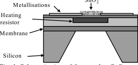
The sensor used consists of a microhotplate platform and a nanoparticular SnO2 sensing layer (Fig.1). A microhotplate architecture has been developed for Motorola and actually exploited by Microchemical
Sensors S.A. A SiOxNy membrane of 1.5 µm of
thickness supports a polysilicon heater of 600 µm x 430 µm. Dimensions have been optimized to achieve good thermo-mechanical reliability [1]. The heater can reach temperatures of 450°C with a power consumption of 83 mW. y = 0.0437x + 47.824 45 50 55 60 65 70 0 200 400 600
T em perat ure ( Celcius degree )
Rh ( ohm ) Silicon Membrane Heating resistor Metallisations SnO 2
Fig. 3: Evolution of heater resistor with the ambient temperature.
Fig. 1: Schematic view of the complete SnO2 gas
SCHEDULE OF CONDITIONS
5 0 5 1 5 2 5 3 5 4 5 5 5 6 5 7 5 8 0 5 00 1 000 1 500 2 000 2 500 T im e ( h ) Rh ( Ω )The design will be done according to the best compromise between sizes, the power consumed, the response time...
Moreover, this system will have to be adaptable on different resistance values and independent of their drift. This prototype must have a low simple supply and will have to consume as least as possible to allow transportability application.
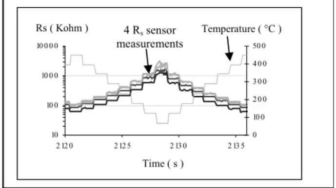
A previous study shows the interest to make the sensor functioning at various temperature values in order to improve the sensitivity and to limit the influence of the relative humidity [3],[4]. We take in reference the following profile (Fig. 6) adapted to the ethylene gas detection in humid atmosphere.
Fig. 4: Temporal drift of heating resistance.
As it is well known, the gas sensitivity of the sensor is tightly dependant with the temperature.
In figure 5, we can see an example of our sensor CO-sensitivity behavior versus applied voltage on heating resistor. The sensitivity is here determined by S = (Rgas-R0)/R0 where R0 is the sensitive layer resistance without gas and Rgas the resistance measured under gas. Time ( s ) R H 0 % 10 10 0 10 0 0 10 0 0 0 2 12 0 2 12 5 2 13 0 2 13 5 Te mp s 0 10 0 2 0 0 3 0 0 4 0 0 50 0 Te mp e ra t ure o C R s Ko hm Time ( s ) Rs ( Kohm ) Temperature ( °C )
Fig. 6: Profile of operating temperature.
4 Rs sensor measurements 0 10 2 0 3 0 4 0 50 1.6 2 2 .4 2.8 3.2 3.6
Applied volt age on heat er resist or ( Volt )
Sensitivity ( % )
We point out the performances of the sensor in Table 1 and we deduce the characteristics following ones in Table 2.
Fig. 5: Example of CO-sensitivity of SnO2 gas sensor
versus heater voltage supply. Table 1: Sensor performances
Range of operating temperature Tamb-450ºC
Power range 0 – 83mW
Response time in temperature < 30ms
Rh range 55 – 70 Ω
Rh temporal drift 10 Ω
We can point out that sensitivity becomes maximum to for a voltage value near 2.8V corresponding to a temperature of 450°C. In consequence, the homogeneity and the good control of the sensitive layer temperature is absolutely necessary. So, the variation or the temporal drift implied by heating resistance will involve a strong reduction of the SnO2 layer sensitivity.
Table 2: Electric characteristics of the module
Range of controlled power 18.5-83 mW
Minimal power variation 5.4mW (25ºC)
Permissive power error 0.54 mW (10%)
In order to counter this problem, various approaches are possible. The first solution would be to place a serial resistance with equivalent value. It may limit this drift and improve sensor lifespan but this solution was not adopted because of its double consumption. The second approach would be to replace polysilicon by a metal. This solution would, in the same time, minimise the time drift and integrate a temperature sensor. However, in order to obtain the same electrothermic performances, active layer dimensions would be greatly increased and technologically, the metal induces mechanical constraints on the membrane. The last solution is to control the power applied on the heating resistor (i.e. to control temperature) because of linear relation between these two parameters.
DESIGN OF THE PROTOTYPE
We must carry out a circuit which has to be realizable firstly in traditional components (demonstrator) and secondly completely integrated on chip (smart sensor). Not being able to avoid power calculation by a numerical solution, the regulation system can be elaborated in both technologies. Accordingly, the first prototype has been developed in an analogue version.
Power Measurement method
In this paper, this last solution has been investigated to develop a “smart” gas sensor integrating the microhotplate with the sensitive layer, the power control unit and the signal treatment.
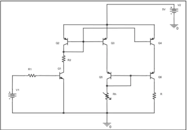
The first module has to realize the power measurement. This analogue module must be completely integrated on chip. That’s why we have used bipolar transistor architecture. This system is based on two current
mirrors ordered in voltage (Fig.7). The interest to use this structure is to be able to impose at the same time, two identical currents to the heating resistor ( Rh ) and to a fix resistor ( R ). These currents are proportional to the wished power. This function is fulfilled by the transistors Q2, Q3 and Q4. Using PNP bipolar transistors permits to avoid calculation of differential voltage at the boundaries of Rh and R. Obviously, this structure has to be realized with paired transistors. This system is ordered by the Q1 transistor and the V1 voltage.
It is noted that the term ε depends on the early voltage,
Rh and R. As shown in figure 8, with PSPICE
simulation, the lower Va is, the more the two collector currents difference increases.
VAF
10V 20V 30V 40V 50V 60V 70V 80V 90V 100V
I(Rmiro ir)- I(R1) -800uA -400uA 0A 400uA ∆ I ( µ A) Va (V)
Fig. 8: Current error versus Va for V1={2;2.5;3;3.25V}.
Q3 Q6 R1 R2 Q1 Q5 0 V1 R V2 5V 0 Rh Q4 Q2
By experimental tests carried out on the transistors used, we have measured an early voltage about 25V. From the curve above, it can be seen current error until 300µA. In order to counter this problem, one adds a second current mirror fulfilled by the transistors Q5 and Q6. Any Rh variation or drift makes the current imposed in this branch varying. The addition of this current mirror reflects the same current fluctuation on R. Before assembling this function, we tested its performances on PSPICE software. Simulations predict us a maximum error of 330 µA with a heating resistance of 51Ω to obtain a maximum power of 83mW.
Fig. 7: Basic circuit for power measurement.
Using an analogical multiplier, its output Vp appears as an image of the power PRH which can be calculated by the following equation:
PRh = Vp/α.R (1)
Where
Power Control Unit
Vp = α Rh.IRh.R.IR (2)The loop of control is based on a proportional regulator type. From the module here-named “power measurement” explained above associated with an analogical multiplier to calculate an image of power on Rh, the power control unit consists of : a first converter to convert the output voltage of the multiplier into a comparable voltage with the input of the system, of a differential amplifier to compare the desired power and the real power on Rh, of a variable gain and a second converter to be well adapted with the “power measurement” module input ordered in voltage (fig .9).
α the attenuation coefficient of the analogical
multiplier, IRh and IR the currents crossed in the two resistors.
From the collector current relation given by equation (3), it can be deduced the relative current error between ICQ4 and ICQ3 (equation (4)). + = T eb a ec s c U V V V I I 1 exp (3) Where Ic the collector current, Is the reverse saturation current, Vec the emitter-collector voltage, Veb the emitter-base voltage, Va the Early Voltage and UT the thermodynamic voltage.
Simulations on PSPICE predict to us that the error in open loop can reach 27mW for a unit gain, an Rh drift of 10Ω and an initial power of 83mW. In closed loop, this error decreases to 7mW. In order to obtain an error lower than or equal to 0.5mW under the same conditions, it is necessary to introduce a gain about 19.5. Va Vec Va Vec Ic Ic Q Q Q Q + + = = 3 4 3 4 ε (4) ε represents this current error.
Vs V Rmiroir VRh Uc Vc E G E Ve Power measurement method Conversion Power-Power Conversion Power-Voltage Vr Fig. 9: Functional description of the power control unit.
EXPERIMENTAL RESULTS
As PSPICE simulations displayed quite good results, we have assembled the complete circuit on a pre-galvanised plate (Fig.10) to show the feasibility. Before proceeding to experimental measurements, the system has to be well calibrated in term of R1, R and G.
Fig. 10: Top view of the prototype.
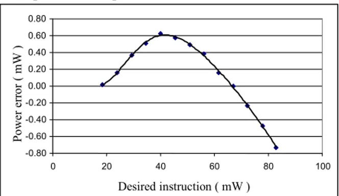
In figure 11a, we can see an example of the power error in all the range of power. We note that this error can reach 0.6mW that correspond to a temperature of 3˚C. After an adequate calibration, the power error according to the Rh drift can be lower than 0.5mW during working power profiles between 18.5 and 83mW (Fig.11b). This profile, shown in Fig.6, corresponds to temperatures from 100 to 450˚C.
-0.80 -0.60 -0.40 -0.20 0.00 0.20 0.40 0.60 0.80 0 20 40 60 80 100 Desired instruction ( mW ) Po we r e rr or ( mW )
Fig. 11a: Example of power error obtained in the power full range.
-0.5 -0.4 -0.3 -0.2 -0.1 0 0.1 0.2 0.3 0.4 0.5 0 5 10 15 20 25 Rh drift ( ohm ) Po we r er ro r (m W ) Pemax = 83 Pemin = 18.47
Fig. 11b: Example of power error obtained at the time of the Rh drift.
We also tested our system at a level of voltage. In figure 12, we can see the influence of the open-loop gain from 1 to 13 over the response time. It is noted that by increasing the gain, we first decrease the static
current error as it has already be shown and we also reduce the temperature response time from 33ms to 10ms. On the over hand, the system becomes divergent with a closed-loop gain higher than 14.
0 5 10 15 20 25 30 35 0 2 4 6 8 10 12 14 Gain ( no unit ) R es po nse ti me ( ms )
Fig. 12: Evolution of the response time according to the closed-loop gain.
The system thus becomes faster while improving the accuracy with a gain equal to 13.
DISCUSSION
At the time of the realization of this system, we ran up against the problem of the Early voltage. We succeeded in countering this problem by obtaining suitable results. But, as this system will be integrated on a chip, its performances would be improved just by using paired integrated transistors with the desired features. About the control part of power, by using CAN and CNA, this system could be all transferred in digital technology. We will then obtain on the same chip, the analogue "power measurement circuit" and the numeric "power control" unit.
CONCLUSION
A new generation of gas sensors based on nanoparticular SnO2 sensitive layer has been elaborated and tested. Its platform is maked up of a membrane and a polysilicon heating resistor. Two phenomena have been observed on the heating resistor behavior : a linear development of the resistance according to the ambiant temperature and a time drift under apply. So, to counter this problems, we have elaborated a power control unit based on two current mirrors and a proportional-type regulation. We have designed a first analog prototype using a very simple structure and which can be integrated on a chip. It yields power error less than 0.6mW corresponding to 3°C temperature error. With this system, we also reduce the response time from 35ms to 10ms. By this improvement, we can make the sensor working with a temperature profile to improve the sensitivity and to limit the influence of the relative humidity. Lastly, this system can be adapted to different resistance values, so to different type of micro-heater.
ACKNOWLEDGMENTS
Authors would like to thank Microchemical Systems S.A which have provided us the micromachined
platforms and the Coordination Chemistry Laboratory for the deposition of SnO2 layer on the micromachined platforms.
AUTHOR AFFILIATIONS
1 Laboratoire d’Analyse et d’Architecture des
Systèmes, Toulouse, France.
2 Université Paul Sabatier Toulouse III, France. 3 Institut National Des Sciences Appliquées, Toulouse, France.
REFERENCES
[1] S. Astie, ”Thermal simulation of an integrated gas sensor using SESES”, LAAS REPORT N° 96504, 1996
[2] C. Nayral, “Synthesis and use of a novel SnO2 nanomaterial for gas sensing”, Applied Surface Science, 2000
[3] T-A. Kunt, T J. McAvoy, R E. Cavicchi, S. Semancik, “Optimization of temperature programmed sensing for gas identification using microhotplate sensors”, Sensors and Actuactors. B, Vol.53,1998, pp.24-43
[4] M. Guerrero, P. Menini, A. Martinez, L. Erades, “Method of C2H4 detection in humid atmospheres
using a nanoparticular SnO2 gas sensor”,