HAL Id: hal-01066415
https://hal.archives-ouvertes.fr/hal-01066415
Submitted on 14 Oct 2014
HAL is a multi-disciplinary open access
archive for the deposit and dissemination of
sci-entific research documents, whether they are
pub-lished or not. The documents may come from
teaching and research institutions in France or
abroad, or from public or private research centers.
L’archive ouverte pluridisciplinaire HAL, est
destinée au dépôt et à la diffusion de documents
scientifiques de niveau recherche, publiés ou non,
émanant des établissements d’enseignement et de
recherche français ou étrangers, des laboratoires
publics ou privés.
WDM optical networks
Bernard Cousin, Joel Christian Adépo, Souleymane Oumtanaga, Michel Babri
To cite this version:
Bernard Cousin, Joel Christian Adépo, Souleymane Oumtanaga, Michel Babri. Tree reconfiguration
without lightpath interruption in WDM optical networks. Int. J. Internet Protocol Technology, 2012,
7 (2), pp. 85 - 95. �10.1504/IJIPT.2012.050217�. �hal-01066415�
Bernard Cousin, Joel Christian Adépo, Souleymane Oumtanaga, Michel Babri
Abstract— Efficient reconfiguration of optical multicast trees in Wavelength Division Multiplexing (WDM) networks is required. Multimedia applications which consume a huge bandwidth, require multicasting. So, multicast concept is extended to optical networks to improve performance. Today, networks are facing many phenomena such as changes in the traffic model, failures, additions or deletions of some network resources due to a maintenance operation. To cope with these phenomena, network operators compute new topology according to the applications requirements. Some real-time multicast applications are not indulgent with lightpath interruptions. So the configuration of the network must be done as quickly as possible to be spontaneously deal with the problem before other events appear and without connection interruption. To the best of our knowledge, there is no work in the literature that considers the reconfiguration of an optical multicast tree to another one without connection interruption. We prove that it is impossible to reconfigure any initial tree into any final tree using only one wavelength and without connection interruption. We propose in this paper BpBAR_2 method, using several wavelengths to reconfigure optical WDM network. This algorithm does tree reconfiguration without lightpath interruption, reduce the reconfiguration setup time and the cost of wavelengths used.
Keywords—Reconfiguration, optical WDM network, multicast tree, reconfiguration sequence, lightpath interruption.
I. INTRODUCTION
oday, network users are increasingly demanding regarding throughput and network Quality of Service (QoS). Networks are frequently faced with events such as changes of traffic, network failures or deployment of new network resources. These events alter the state of the network, moving its topology away from the optimum. Network operators then use some techniques such as traffic engineering, the creation of backup paths or network reconfiguration to address these phenomena. Protection (backup paths) is a fast and effective technique of response for network failures. Networks resources are reserved in a proactive manner. It improves the performance of traffic delivery but not optimize the use of bandwidth. Traffic engineering is used to place new traffic where capacity allows but not change the existing paths of the traffic. Yet the goal of our work is the configuration of current topology to another one. So our study concerns network reconfiguration which is also called topology engineering. Network reconfiguration occurs to optimize network performance (meet more traffic requests while minimizing the cost and maximizing network utilization) and the delivery of traffic (Wu, 2011). Reconfiguration in networks consists of three sequential and iterative phases (Wu, 2011). The first
phase is decided by the reconfiguration policy. The outcome of this phase is to decide if the reconfiguration will take place or not. A positive response to this phase leads to the execution of the second phase. The second phase computes a new topology to meet the requirements. Once the new topology is computed, the final phase the migrating from the current topology to the new topology. Reconfiguration of Optical Wavelength Division Multiplexing (WDM) (Mukherje, 2000; Ramaswami, 2006) networks is very beneficial because WDM networks are now widely deployed due to their high bandwidth and low error rates. Optical networks are networks wherein nodes are switches and are connected with optical fibers. An optical connection in this network is a pair of a transmitter and a receiver that wish to communicate using a certain wavelength1. The path uses by a connection is called lightpath. An optical channel is a signal transmitted at one wavelength in one fiber. Optical network is subject to two constraints: wavelength continuity constraint and distinct wavelength constraint. The wavelength continuity constraint requires that the same wavelength should be retained over all the links in a lightpath in the absence of wavelength converters. A wavelength converter is a component which converts incoming signal's wavelength to a different outgoing wavelength, entirely in the optical domain. The distinct wavelength constraint requires that two lightpaths cannot be assigned with the same wavelength if they are not on disjoint links. WDM networks require improved management and a well-planned reconfiguration to meet QoS requirements (Geary and al, 2002). WDM reconfiguration is a challenge because it temporary release network resources such as transmitters, receivers and wavelengths which can cause loss of data in high-rate traffic flow; and it must minimize also the lightpath reconfiguration time (Golab and Boothbay, 2004; Wei, 2002).
In the process of WDM network reconfiguration, the third phase is completed online through the establishment of new lightpaths, and removing or changing of existing lightpaths (Wu, 2011). Switches that make up the new topology and those of the former topology must be reconfigured to take into account new parameters to update its forwarding table (routing and switching) and resource management parameters (buffer, output queue and input queue of the node) (Cousin and Molnar, 2007). Wavelengths carry a lot of traffic, thus they are often sensitive to interruption or transmission delay. Interruption of a lightpath can cause damage to all
1 If wavelength converters are available in the network, the wavelength
continuity constraint is not applied. In this case, a connection use a certain sequence of wavelengths.
Tree Reconfiguration without Lightpath
Interruption in WDM Optical Networks
communications using this wavelength. The configuration of the paths must be executed in a coordinated manner to maintain the connexity of the lightpath. Connection management in WDM networks can be provided by GSMP protocol (Doria et al., 2002), for instance. The reconfiguration technique used by this protocol is to close the old connection before establishing a new. This does not guarantee the continuity of traffic. In addition, it is not optimal in terms of duration of reconfiguration. Network reconfiguration must be done as quickly as possible to spontaneously deal with the problem before other events happen in the network.
Reconfiguration can be deployed in a centralised or a distributed manner. In the distributed approach, each node needs more processing. In addition, the triggering of different reconfiguration operations by the node needs synchronization to avoid interruptions. This synchronization is difficult in the distributed manner. In the centralized manner, a network controller has a global view of the network topology, link and node utilization, and traffic demand. This node coordinates reconfiguration process. The reconfiguration function may be implemented in a Path Computation Element (PCE) as part of the centralized management system (Farrel et al., 2006). So in this manner, synchronization which is needed by the distributed approach of reconfiguration is not required. In this work, we assume reconfiguration is controlled in a centralized manner. So when a network reconfiguration is required, the network controller sends configuration messages to all the switches which must be configured. The problem now is the scheduling of configuration messages to ensure continuity of traffic. The network controller must send its configuration messages in a coordinate manner. This amount to solve the problem of what sub-set of switches must be configured before any other.
Applications such as multimedia, IPTV and video conferencing require multicasting. In point-to-point communication networks, multicasting is performed by sending a separate copy of data from the source to each destination. This technique consumes a huge bandwidth. An efficient technique to support these applications is to route data toward multiple destinations over a multicast tree. This reduces the resource cost used in optical networks since the same channel on some tree branches can be shared by many destinations. Thus, multicast concept is extended to optical networks to improve performance (Ding and Poo, 2003; Malli et al., 1998). In the case of optical networks, the set of tree paths used is called a light-tree. This is a generalization of the lightpath word, which is used in the unicast case. A light-tree is an all-optical channel (using the same wavelength on each link of the tree) originating at a given source node, and has multiple destination nodes. To extend multicast to optical networks, switches must be equipped with light splitters that duplicate incoming light signal to one or several output ports (Zhou, Molnar, and Cousin, 2009). When a switch has an infinite splitting capacity that means its splitting capacity is bigger than the maximal nodal degree of the switch. The wavelength continuity constraint and the distinct wavelength constraint are also extended to light-trees. In our work, we assume that multicast tree reconfiguration must be done without light-tree interruption. Then, the chosen
reconfiguration process must reduce the reconfiguration setup time, and finally reduce the cost of the wavelengths used. This problem is scientifically difficult due to the numerous constraints of WDM networks added to the continuity of traffic toward all the destinations of a multicast group.
In the following, in Section II, we present the related work on multicast reconfiguration. Section III presents our formulation of the multicast reconfiguration problem, give the objectives of reconfiguration. Then, we present multicast reconfiguration using a single wavelength, multicast reconfiguration using several wavelengths and our proposal multicast reconfiguration algorithm. This algorithm allows reconfiguration without connection interruption, with a short duration and an efficient use of network resources. In Section IV, we present the results of evaluation and the performance analysis. Finally, we conclude this paper in Section V
II. RELATEDWORK
The existing works on reconfiguration is generally concerned with determining the new topology, the frequency of reconfiguration execution while minimizing interruptions. In Baldine and Rouskas (1999; 2001), reconfiguration is proposed as a solution to traffic changes. It uses a centralized strategy based on Markov model to determine a virtual topology insensitive to traffic changes. In Kárász, and Pándi (2005), the reconfiguration performed on short-term change is proposed for traffic over a long period. Reddy et al. (2000) proposes a strategy for establishing new lightpaths in order to cope with network failures and minimize interruptions of optical connections. Kardsz (2006) compares different reconfiguration policies depending on the frequency of reconfiguration and the network type to add new resources. Cousin and Molnar (2007) propose a reconfiguration algorithm for unicast traffic. The proposed algorithm allows for the configuration of an initial path to another in a small number of steps and without connection interruption.
Few studies (and none of the above) have focused on multicast tree reconfiguration in the literature. In Perényi et al. (2008), regular reconfiguration of light-tree to meet the degradation of the tree due to the dynamic behavior of its leaf nodes is studied. To avoid connection interruptions which are not tolerated by the real-time applications, the reconfiguration in this case will set up the new tree before the destruction of the old. But the disadvantage of the proposal method is that both trees exist and data are duplicated for a short time. This wastes a lot of network resources due to the existence of two trees. In addition, the regular is benefic when the process is quick, thus minimizing the reconfiguration duration. A grooming algorithm called ReLT is proposed in Huang et al. (2004) to determine the routing of new requests and minimize the blocking probability. The principle of this algorithm is that trees can be reconfigured dynamically to meet new destinations and respond to new requests. Reconfiguration with that algorithm is to extend the branches of the tree beyond the initial leaves to reach new destinations. To apply this algorithm, an auxiliary graph is generated from the physical network. Then, a subroutine in ReLT is executed each time a new request arrives to determine the possibility of
satisfying the new request in terms of residual capacity on auxiliary graph or setup a new light-tree for it.
To the best of our knowledge, there is no work in the literature that considers the reconfiguration of an optical multicast tree to another one without connection interruption. The existing works on multicast reconfiguration are interested by the computing of new multicast tree, the different reconfiguration triggering strategies and the reconfiguration frequency. The reconfiguration consists in going from one tree to another without connection interruption is the subject of our study.
III. MULTICASTRECONFIGURATIONPROCESS
A. Formulation of the problem
Let T0= (E0, V0) and Tz = (Ez, Vz) be two trees with the same source and the same set of destinations. E0 and V0 represent respectively the set of nodes and the set of edges of the initial tree. Ez and Vz represent respectively the set of nodes and the set of edges of the final tree. A node represents a switch on the physical network and an edge represents a fiber link. We want to move from a tree T0 to a tree Tz. Each
step we configure simultaneously only one sub-set of nodes, one sub-set after the others, since each step must ensure the continuity of communication between the source and each destination. Thus we produce a series of trees T0, T1, T…, Tz-1, Tz.
Four kinds of configuration operations are possible on a switch: addition of light switching for a wavelength, deletion of light switching of a wavelength and a combined operation between two output ports on the same switch for the same wavelength. The addition of a light switching for wavelength l on a switch X from an input port i to an output port j is noted (+i, X, l, j). The post-condition of this operation is that the wavelength l is busy on the output j of the switch X. After this configuration operation, any signal received at the input port i is propagated to the output port j of the same switch. If the switch X has already switched the light for wavelength l from the input port i to the output port k, X becomes a branching node.
The deletion of a light switching of wavelength l on a switch X from an input port i to an output port j is noted (-i, x, l, j). The pre-condition of this operation is that the wavelength
l is busy on input port i and on output port j. The
post-condition is that wavelength l is released only on the output port j of the switch X if the switch has switched the light for wavelength l from the input port i to several output ports. If the switch has switched the light for the wavelength l from the input port i to just one output port j, wavelength l is released on the output port j and the input port i of the switch X. After this operation, no signal in wavelength l is out of output port j on switch X. If the switch X has not switched the light for wavelength l from the input port i to the output port j, then the operation is empty. Incast switching is forbidden.
The third operation is a combined operation between two output ports on the same switch for the same wavelength. This involves the deletion of a light switching of wavelength l on a switch X from an input port i to an output port j then the addition of a light switching for wavelength l on the same switch X from the same input port i to an output port j. This
operation is noted (i, X, l, j=>k) and is equivalent to (-i, X, l, j) then (+i, X, l, k).
The last operation is the wavelength conversion operation noted (i, X, l=>m, j). This operation convert wavelength l of the input port i to m on the output port j.
For the four kinds of configuration operations, the input port i and the output port j can, respectively, be identified by the IDs of the upstream and the downstream switches, if and only if two switches are linked by at most one optical fiber. And the wavelength of an output port of a switch can not be fed by more than one input port.
We assume that no major discontinuity of the light signal appears when a light for a wavelength is switched from an output port of a switch to another output port of the same switch. We will use this property to study good reconfiguration sequences which should guarantee the continuity of the tree during its reconfiguration. The best reconfiguration sequence will be the shortest (we assume that any configuration operation has the same duration).
B. Objectives
The multicast reconfiguration process aims at three objectives. First, the reconfiguration of the light-tree must be done without connection interruption. Then, it must reduce the reconfiguration setup time, and finally reduce the cost of the wavelengths used.
This problem will be tackled in two study contexts depending on whether all switches are equipped with converters or not. In the first context, we assume that all the switches are not equipped with wavelength converter. So, we want to study if it is possible to reconfigure a tree using only one wavelength for all trees of a tree series (initial, intermediate, and final trees). In the second context, we assume that all the switches are equipped with wavelength converter. So, several wavelengths can be use for reconfiguring from the initial tree to the final one. However and obviously, the initial tree and the final one must use the same wavelength.
C. Multicast reconfiguration using a single wavelength
Let us consider the first study context which consists in using a single wavelength and the same for all trees of a tree series during the reconfiguration process of a tree. We want to demonstrate that in general it is not possible to reconfigure an initial tree into a final tree using only one wavelength and without any tree discontinuity.
Let us suggest that for any multicast problem composed of trees Ti and Ti+1, we can move from Ti to Ti+1 with only one
wavelength l and without interruption of the tree data flow. Let us then consider the reconfiguration problem formed by the following trees (see Figure 1):
T0:{S{A{C;B{D}}} is the initial tree (in red) using a single
wavelength l and Tz :{S {B{A{C }; D}} is the final tree (in
blue) using the same wavelength. Node S (resp. nodes C and D) is the source (resp. are the destinations) of the optical tree.
Figure 1: Initial tree T0 (red) and final tree Tz (blue)
We will study the configuration from one tree to another one by exploring all the possible reconfiguration sequences of nodes. In the unicast case, a node has at most one output interface per path. Therefore the configuration of this interface means the reconfiguration of the node; at most one configuration operation is required for each node in the network to reconfigure one initial lightpath into one final lightpath. But in the multicast case, a node can have several output interfaces. Then the reconfiguration of a node in the multicast case means the configuration of only one output interface for this node. Furthermore, it is never necessary to configure the destination node, (so in our case, only the tree nodes: S, A and B can be configured). A node can have several output interfaces. As a result it can appear several steps in a reconfiguration sequence according to the number of output ports.
By grouping the reconfiguration sequences according to the node from which the reconfiguration begins, we obtain the three following cases:
Case 1: Reconfiguration sequences beginning with node A The wavelength l is busy on all the ports of switch A in the initial tree; so we cannot plan to add an operation of type (+B, A, l, C). Other possible operations on node A are (-S, A, l, D) and (-S, A, l, B). But, at the risk of interrupting the existing connection, we can no longer begin the reconfiguration with an operation of type: (-S, A, l, D) or (-S, A, l, B). So the reconfiguration sequences beginning with node A are not possible.
Case 2: Reconfiguration sequences beginning with node B The wavelength l is busy on all the ports of switch B in the initial tree To. So we cannot add any operation of type
(+S, B, l, A) or (+S, B, l, C). We cannot neither add an operation of type (-A, B, l, D), otherwise we interrupt the connection towards the destination D. As a result, the reconfiguration process beginning with node B is not possible.
Case 3: Reconfiguration sequences beginning with node S First we carry out the operation (+S, l, B). Then the wavelength l is busy on all the output ports of switch B. The operation of type (+S, B, l, C) or (+S, B, l, A) cannot be carried out. We cannot neither add an operation of type (-A, B, l, D), otherwise the connection to the destination D is interrupted. In the same way, the wavelength l being busy on all ports of switch A on the initial tree, w e cannot plan to activate an operation of type (+B, A, l, C). Then, at the risk of interrupting the existing connection, we can no longer plan an operation of the type:(-S, A, l,
D) or (-S, A, l, B). As a result, the configuration sequences beginning with node S are not possible. We conclude that, for this problem, none reconfiguration sequence enables to reconfigure initial tree To into final tree Tz, without any major interruption of the tree data flow. This can be explained by the fact that the reconfiguration of one tree into another is done by the addition or the deletion of a ligth switching operation. The pre-condition of an addition of light switching for a wavelength is that the wavelength is free on the output port of the switch. That is not verified for at least one node of each of the possible reconfiguration sequences of our reconfiguration problem (Described Figure 1). The post-condition of a deletion of light switching of a wavelength is that the wavelength is free on the output port of the switch. That is also not feasible when the wavelength is shared by several destinations.
So if in a tree reconfiguration problem using a single wavelength, none reconfiguration sequence is possible, then we can conclude that this problem is not realizable.
We can yet conclude that the reconfiguration problems using a single wavelength whose initial and final trees share at least one edge (let’s say a fiber link to the optical network) are impossible. However there are some limit cases, where tree reconfiguration is feasible.
Case 1: when both initial and final trees are the same, the solution is to realize no reconfiguration .So it exists a solution of the tree reconfiguration problem using only one wavelength despites the fact that the trees (initial and final) share at least one edge.
Case 2: when there is strictly the same branch for both trees between the sources and a sub-set of destinations and strictly different branches between the source node and the complementary sub-set of destinations.(i n this case), the solution will consist in reconfiguring with only the same wavelength the branches which are totally different between the two trees.
In conclusion, on whatever network topology, it is impossible to reconfigure any initial tree into any final tree using only one wavelength and without flow interruption. However we show on the next section whether and how it is possible using several wavelengths.
D. Multicast reconfiguration using several wavelengths
Let’s consider the second context in which several wavelengths is used for configuring an initial tree into a final tree without tree interruption. However and obviously, the initial tree and the final tree use only one wavelength (the same wavelength). Let's prove that, whatever network topology is used, it is possible to reconfigure, without flow interruption, any initial tree into any final tree. Let’s use a branch by branch back and forth reconfiguration process what will be called BpBAR. Let’s suppose that a is the wavelength used by the initial light-tree. Establish a new branch for a destination on a new topology between the source and the destination by using another wavelength b. And switch at the source from a to b for this destination only. Then, delete the
exclusive part of the old branch toward the destination which uses wavelength a. Repeat the same action for all the destinations. The new tree (a tree according to the new topology) powered by b is obtained. Then a new non-powered tree should be established with wavelength a by using the previous process, and switch from the source of b to a. Then make the configuration of the initial tree T0 to the final tree Tz by producing a series of trees.
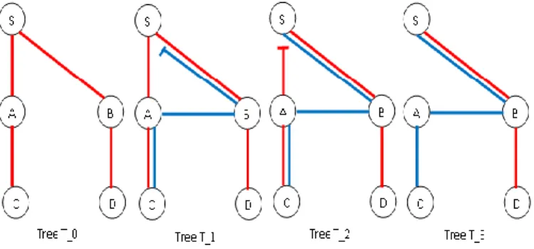
The branch of the initial tree from the Source S to the destination i is Br0(S, i) and the one of the final tree is Brz(S, i). For instance, let’s consider the reconfiguration problem given by the two following trees (see Figure 2): To
:{S{B{A{C}; D}}}, the initial tree using a wavelength a (in red) and Tz: {S{A{C}; B{D}}}}, the final tree (in blue).
Figure 2: Initial tree T0 and final tree Tz
In the application of the reconfiguration process branch by branch, the policy can decide to establish first the branch Brz(S, C) then the branch Brz(S, D ) or the branch Brz(S, D) and then the branch Brz(S ,C) . Let’s suppose that it decides to first configure then on-powered branch Brz(S, C) after a series of steps. We obtain the tree on Figure 3.
Figure 3: Establishment of a non-powered branch Brz (S, C)
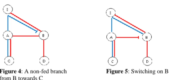
The following step is the light feeding of the new branch and the deletion of the old branch. But on this tree (see Figure 3), reconfigure the source S will certainly feed the new branch with the light but it will interrupt the lightpath toward the other destinations. Indeed, the source S is not the right node for the switching. It must be done on a node on which the connection of the exclusive part of the old branch which needs to be established can be break. For this problem, it is the node B. So the new branch Brz(S, C) is fed from the node B. This requires a wavelength converter in B. The following trees: (see Figure 4 and Figure 5) is obtained.
Figure 4: A non-fed branch Figure 5: Switching on B
from B towards C
Then reconfigure the source S to delete the part between the nodes S and B on the current tree. The node through which the switching for a new branch is done in the back stage will be called Com1 and the one through which it is done on the forth stage will be called Com2. Now the question is how to determine Com1 and Com2 for the establishment of a new branch.
In the back stage of process BpBAR, during the switching on Com1, the traffic of the exclusive part of the old branch towards the concerned destination is break So, Com1 is chosen with the result that its reconfiguration doesn’t interrupt the flow towards the other destinations and that it also allows to feed with light the new branch. Therefore, for a destination i,
Com1 must be a node of Bro(S, i) allowing the feed of the new branch Brz(S, i). Then, it must be a branching node of the current tree for the optical channels of the initial tree and be the closest to the destination i. This criterion ensures that the switching doesn’t interrupt the connection toward the other destinations. The source node meets always the criteria for determining Com1. So it is the default Com1 node.
Com2 is the branching node of the current tree belonging to
the chosen branch Brz(S, i) which uses the optical channel of the final tree and which is the closest to the destination i. The source node meets always the criteria for determining Com2. So it is the default Com2. The use of Com1 and Com2 requires a wavelength converter in these switches.
Since the switching nodes can be determined once the topology of the trees is known, we define a first multicast configuration process, called BpBAR.
BpBAR Reconfiguration process It is described in the following steps:
1. Chose a branch Brz(S, i) according to the new topology. Initially Com1=S; search Com1 and reconfigure one by one the ports of the nodes between the destination i and the source S and those between S and Com1.
2. Configure Com1 to feed the new branch and interrupt the flow on the old one.
3. Configure one by one the ports of the nodes between
Com1 and i on Bro(S, i) to remove it.
4. If Com1 is different from S, then reconfigure S to interrupt the part between S and Com1.
In case step 4) is realized then execute step 5)
5. Configure one by one the ports of the nodes between S and Com1 to remove this part.
6. Repeat steps 1) to 4) till the establishment of all the new branches.
7. Chose a branch Brz(S, i) on the new topology. Initially
Com2=S; search Com2 and reconfigure one by one the
ports of the nodes between i and Com2 on Brz(S, i) to establish the branch.
8. Configure Com2 to feed the new branch and interrupt the flow on the old one.
9. Configure one by one the ports of the nodes between S and the destination i to remove the old branch.
10. Repeat steps 7) to 9) till the establishment of all the new branches.
BpBAR reconfiguration process ensures the existence of a tree established in the source of the traffic at each step, hence the continuity of the traffic. But it produces a very long sequence of steps. In the example described in Figure 5, to establish the branch Brz (S, C), one operation is done on one and only one node at each step. All these operations have no consequences on the continuity of the existing traffic and on their order. As a result all these ports of nodes can be configured in only one step. The solution is to configure them in parallel. So the question is what ports can be configured simultaneously in one step.
The process consisting in establishing the new tree branch by branch, for a given tree, all the series of actions which enable to establish a new non-fed branch can be executed simultaneously. Then make the switching to feed the new branch and interrupt the flow of the exclusive part of the old branch. The series of steps which enables to remove the exclusive part of the old branch can be executed simultaneously in only one step. These operations can be done simultaneously since the ports leading to the destination of this new branch are not used for the traffic before the switching. In addition, after the interruption of the connection, the old branch is no longer used for the traffic. Moreover, they don’t require order in their reconfiguration. In the example described in Figure 2, 6 different steps are produced to establishing the branch Brz(S, C). Steps 1 to 3 can be conducted simultaneously in only one step to establish the non-powered branch Brz(S, C ). Then the switching is done on S and steps 5 and 6 can be conducted simultaneously to remove the exclusive part of branch Bro(S, C). The following 3 steps are produced (see Fig.6):
Figure 6: Establishment of the branch Brz (S, C).
As a result, the determination of operations to realize simultaneously during the reconfiguration process enables to reduce the number of the reconfiguration steps. So the reconfiguration process called BpBAR_1, in which simultaneous operations are allowed, optimizes BpBAR. BpBAR_1 reconfiguration process
It is described in the following steps:
1. Choose a branch Brz(S, i) on the new topology.
Initially Com1=S; search Com1 and configure simultaneously the ports of the nodes between the source S and the destination i and those between S and Com1. 2. Configure Com1 to feed the new branch and interrupt the flow on the old one.
3. Configure simultaneously the ports of the nodes between Com1 and i on Br0(S, i) to remove it.
4. If Com1 is different from S, then configure S to interrupt the part between S and Com1.
In case step 4) is realized, then execute step 5)
5. Configure simultaneously the ports of the nodes between S and Com1 to remove this part.
6. Repeat steps 1) to 4) till the establishment of all the new branches.
7. Choose a branch Brz(S, i) on the new topology. Initially
Com2=S; search Com2 and reconfigure simultaneously
the ports of the nodes between i and Com2 on Brz(S, i) to establish the branch.
8. Configure Com2 to feed the new branch and interrupt the flow of the old branch.
9. Configure simultaneously the ports of the nodes between S and destination i to remove the old branch. 10. Repeat steps 7) to 9) till the establishment of all the new branches
BpBAR_1 allows the reconfiguration of problem described in Fig. 2 into 12 steps.
In the multicast reconfiguration problem described in Fig. 2, branch Br0(S, D) has been destroyed and restored after. But this branch already belonging to the initial tree and using the same optical channels as the final tree no longer requires a reconfiguration. The branches of the new tree which need to be established are the branches which are different from the branches of the initial tree. So in this example, the only branch to be established is Brz(S, C). We suggest the process BpBAR_2 bellow:
Our proposed process: BpBAR_2 reconfiguration process It is described in the following steps:
1. Choose a branch Brz(S, i), different from the branches of the initial tree.
Initially Com1=S; search Com1 and configure simultaneously the ports of the nodes between the destination i and the source S and those between S and
Com1.
2. Configure Com1 to feed the new branch and interrupt the flow on the old one.
3. Configure simultaneously the ports of the nodes between Com1 and i on Br0(S, i) to remove this part. 4. If Com1 is different from S, then reconfigure S to interrupt the part between S and Com1.
If step 4) is realized, then execute step 5)
5. Configure simultaneously the ports of the nodes between S and Com1 to remove this part.
6. Repeat steps 1) to 4) till the establishment of all the new branches.
7. Choose a branch Brz(S, i) on the new topology. Initially
Com2=S; search Com2 and reconfigure simultaneously
the ports of the nodes between i and Com2 on Brz(S, i) to establish the branch.
8. Reconfigure Com2 to feed the new branch and interrupt the flow of the old branch.
9. Configure simultaneously the ports of the nodes between S and destination I to remove the old branch. 10. Repeat steps 7) to 9) till the establishment of all the new branches.
The following 6 steps (see Figure 7) are produced with the problem described in Figure 2.
Figure 7: Reconfiguration with BpBAR_2 process IV. EVALUATION AND PERFORMANCE ANALYSIS
The network topologies used to value our process are COST 239 (see Figure 8) and NSF Network (see Figure 9). They are two topologies frequently used in scientific works in this field.
Figure 8: Topology of COST 239 network
Figure 9: Topology of NSF Network
The steps bellow allows determining the initial and final trees. We use two different kinds of tree in a graph: the shortest paths tree and the minimum spanning tree. The shortest path tree is a tree of shortest paths from a node to every network node. The root of this tree is the initial node. The minimum spanning tree is the tree in a graph which has the minimal total cost of the edges.
1. Select with a uniform distribution law the root of the tree, then choose among the remaining nodes N destinations also with an uniform distribution law, and is the number of the network nodes.
2. a) Use Dijkstra’s algorithm (Dijkstra, 1959) between the source and each destination to produce the shortest path tree which represents the initial tree. b) Use Prim’s algorithm (Prim, 1957) to determine
the minimum spanning tree in the network from a node used as a root. By considering the branches of the minimum spanning tree made by the source and each destination, we obtain the final tree.
The tree obtained at the end of each reconfiguration step is represented by a matrix of optical interconnection. A coefficient of this matrix represents the number of optical channels of the link identified by its two end nodes. The two end nodes of a link characterize a coefficient in the matrix To evaluate the additional cost of a reconfiguration sequence, the expression of the additional cost of a reconfiguration sequence is defined. Let’s define:
The charge (Ch) of a tree Tk is defined by:
(1)
n is the number of the network nodes, and p is the number of
different wavelengths used.
Cout_add (Tk): Additional cost of a tree Tk
0 1 2 8 6 3 4 7 12 11 10 5 13 9 0 1 2 6 7 3 4 5 10 9 8
Gk: Graph obtained at step k with the established channels of the initial tree or the final tree at this step
(2) (3)
In the expression of the additional cost, without loss of generality, we assume that any reconfiguration step has the same duration and all the wavelengths have the same cost on the fiber links.
The additional cost of a reconfiguration sequence Seq = {To, … Tz}, where represents the number of steps is:
(4) The calculation process, called Monte Carlo Method, is used to calculate the average number of reconfiguration steps and the average cost of the additional cost in each topology. For the COST 239 topology, the number of generated pairs of trees is fixed to 5000 for a run of each configuration process with a given parameter set. This number is chosen experimentally. Let’s take an initial tree. Then, let’s take a final tree different from the initial one. The different nodes of these trees are identified by a number between 0 and 10. For each draw of a pairs of trees, different size of the destinations groups is considered. The size of a group is determined with a uniform law and is between 1 and 10. And the different destinations of a group are also determined with a uniform law. Then, we have calculated the average of the number of steps and additional cost for 1000, 2000, and 5000 generations of pairs of trees. For each of these values, we have run each program several times in order to see how the average ranges. For 5000, the average changed with a variation percentage of 03.88%. So we kept 5000 generations of pairs of trees to calculate the average and the variance of the selected metrics. For the topology NSF Network, the number of the generated range of pairs of trees is fixed to 10000; the variation rate for 10000 generations is 03.53%. The results are recorded in tables I, II, III, and IV.
TABLE I
AVERAGE AND STANDARD DEVIATION OF THE NUMBER OF STEPS FOR EACH RECONFIGURATION PROCESS IN COST 239
Configuration process Average (steps) Standard deviation (steps) Percentage of reduction compared to BPBAR MIN/MAX (steps) BPBAR 59.86 37.51 0% 9/149 BPBAR_1 31.75 20.19 46.95% 6/68 BPBAR_2 18.07 12.09 69.81% 6/51 TABLE II
AVERAGE AND STANDARD DEVIATION OF ADDITIONAL COST FOR EACH RECONFIGURATION PROCESS IN COST 239
Configuration process Average (steps) Standard deviation (steps) Percentage of reduction compared to BPBAR MIN/MAX (steps) BPBAR 685.66 756.49 0% 14/3451 BPBAR_1 356.89 372.79 47.94% 10/1538 BPBAR_2 166.84 195.57 75.66% 10/861 TABLE III
AVERAGE AND STANDARD DEVIATION OF THE NUMBER OF STEPS FOR EACH RECONFIGURATION PROCESS IN NSF NETWORK
Configuration process Average (steps) Standard deviation (steps) Percentage of reduction compared to BPBAR MIN/MAX (steps) BPBAR 107.54 60.87 0% 9/238 BPBAR_1 47.02 27.29 56.27% 6/91 BPBAR_2 22.62 17.35 78.96% 6/74 TABLE IV
AVERAGE AND STANDARD DEVIATION OF THE ADDITIONAL COST FOR EACH RECONFIGURATION PROCESS IN NSF NETWORK
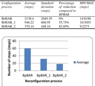
Configuration process Average (steps) Standard deviation (steps) Percentage of reduction compared to BPBAR MIN/MAX (steps) BPBAR 2138.4 2049.39 0% 14/8180 BPBAR_1 946.22 866.95 55.75% 10/3055 BPBAR_2 370.14 448.16 82.69% 9/2273
Figure 10: Average number of steps for each reconfiguration process in
COST 239
Figure 11: Average additional cost for each process in COST 239 0
20 40 60 80
BpBAR BpBAR_1 BpBAR_2
N u m b e r o f ste p s (st e p s) Reconfiguration process Average 0 200 400 600 800
BpBAR BpBAR_1 BpBAR_2
A d d ition n al c o st (WL) Reconfiguration process Average
Figure 12: Average number of steps for each reconfiguration process in NSF
Network
Figure 13: Average additional cost for each process of reconfiguration in NSF Network
All the multicast tree reconfiguration processes described, do the reconfiguration without connection interruptions. So to evaluate the performance of BpBAR_2, a comparison to BpBAR is done. The different metrics chosen are the number of steps and additional cost produced by any sequence of reconfiguration. Tables I to IV compare the earning of each process over the BpBAR process. The number of steps produced by BpBAR_2 is reduced compared to BpBAR, with a gain of 69.81 % in COST 239 and 78.96 % in NSF Network. So BpBAR_2 reduce the reconfiguration setup time. In addition, BpBAR_2 uses respectively 75.66% and 82.69% of wavelengths less compared to BpBAR in COST 239 topology and NSF Network. So BpBAR_2 reduced the cost of wavelengths used. We assume that similar benefit will be achieved on many topologies because the two selected network topologies were real topologies and have been used intensively in many others scientific papers. Similarly we have select two very well know multicast tree computation algorithms (Dijkstra's and Prim's).
V. CONCLUSION
Multicast tree reconfiguration in WDM optical network is studied in this paper. The problem we have considered is to determine an algorithm which allows the configuration from an initial tree into a final one. This configuration must be done by maintaining continuity of data flow towards all destinations reducing the cost of wavelengths used and reducing the duration of the process. To the best of our knowledge, there is
no work in the literature that considers the reconfiguration of an optical multicast tree to another one without connection interruption. The existing works on multicast reconfiguration are interested by the computing of new multicast tree, the different reconfiguration triggering strategies and the reconfiguration frequency. In a first aspect, we study the possibility to solve this problem with a single wavelength during all the tree configuration steps. The conclusion of this study is that on whatever network topology, it is impossible to reconfigure any initial tree into any final tree using only one wavelength and without flow interruption. In a second aspect, several wavelengths are allowed to be used when a tree is reconfigured. We proposed an algorithm called BpBAR_2. This multicast tree reconfiguration process uses the property that no major interruption of the light signal appears when a wavelength is switched from an output port of a switch to another output port of the same switch. BpBAR_2 allows for tree reconfiguration without connection interruptions while reducing the reconfiguration setup time and the cost of wavelengths used.
REFERENCES
Baldine, I. and Rouskas, G. N. (1999) ‘Dynamic reconfiguration policies for WDM networks’, 18th Annual Joint Conference of
the IEEE Computer and Communications Societies
(INFOCOM 1999).
Baldine, I. and Rouskas, G. N. (2001) ‘Traffic adaptive WDM networks: a study of reconfiguration issues’, IEEE/OSA Journal of Lightwave Technology.
Cousin, B. and Molnar, M. (2007) ‘Fast reconfiguration of dynamic networks’, International Workshop on Dynamic Networks. Dijkstra, E. W (1959) ‘A note on two problems in connexion with
graphs’, Numerische Mathematik, Vol. 1, No. 1, pp. 269-271. Ding, A. and Poo, G.-S. (2003) ‘A survey of optical multicast over
WDM networks’, Computer Communications, Vol. 26, No. 2, pp. 193-200.
Doria, A. et al. (2002) ‘General Switch Management Protocol (GSMP) V3’, Internet RFC 3292.
Farrel, A. , Vasseur, J.-P. and Ash, J. (2006) ‘A path computation element (PCE)-based architecture’, Request for Comments 4655.
Geary, N et al. (2002) ‘The benefits of reconfiguration in optical networks’, 10th International Telecommunication Network Strategy and Planning Symposium.
Golab, W. and Boothbay, R. (2004) ‘WDM optical network reconfiguration using automated regression-based parameter value selection’, 3rd International Conference on Networking. Huang, X. et al. (2004) ‘Dynamic multicast traffic grooming in
WDM networks with reconfigurable light-trees’, Optical Society of America.
Kárász, T. and Pándi, Z. (2005) ‘Optimal reconfiguration of provisioning oriented optical networks’, proceedings of the 3rd International Working Conference on Performance Modeling and Evaluation of Heterogeneous Networks (HET-NETs). Kardsz, T. (2006) ‘Consolidation strategies of provisioning oriented
optical networks’, Journal of Optical Networking, Vol. 5, No. 6, pp. 445-462.
Malli, R., Zhang, X. and Qiao, C. (1998) ‘Benefit of multicasting in all-optical networks’, SPIE All Optical Networking, Vol. 2531, pp. 209-220.
0 50 100 150
BpBAR BpBAR_1 BpBAR_2
N u m b e r o f ste p s (st e p s) Reconfiguration process Average 0 500 1000 1500 2000 2500
BpBAR BpBAR_1 BpBAR_2
A d d ition al c o st (WL) Reconfiguration process Average
Mukherje, B. (2000) ‘Wdm optical communication network: progress and challenges’, IEEE Journal on Selected Areas in Communication, Vol. 18, No. 10, pp. 1810-1824.
Perényi, M. et al. (2008) ‘Regular reconfiguration of light-trees in multilayer optical networks’, 12th Int. Conference on Optical Networking Design and Modeling (ONDM 2008).
Prim, R.C. (1957) ‘Shortest connection networks and some generalizations’, Bell System Technical Journal, Vol. 36, pp.1389–1401.
Ramaswami, R. (2006) ‘Optical networking technologies: what worked and what didn’t’, IEEE Communications Magazine, Vol. 44, No. 9, pp. 132-139.
Reddy, G. S. K. , Manimaran, G. and Murthy, C. S. R. (2000) ‘Reconfiguration based failure restoration in wavelength-routed WDM networks’, International Conference on Dependable Systems and Networks (DSN 2000).
Wei, J. Y. (2002) ‘Advances in the management and control of optical internet’, IEEE Journal on Selected Areas in Communications, Vol. 20, No. 4, pp. 768-785.
Wu, J. (2011) ‘A Survey of WDM network reconfiguration: strategies and triggering methods’, Computer Networks, Vol. 55, No. 11, pp. 2622-2645.
Zhou, F., Molnar, M. and Cousin, B. (2009) ‘Multicast routing and wavelength assignment in WDM mesh networks with sparse splitting’ EuroNF Workshop on Traffic Management and Traffic Engineering for the Future Internet.
BIOGRAPHICAL NOTES
Bernard Cousin is professor at the University of Rennes-1 (France). He got the Doctorat d'Université in 1987 from the University of Paris-6, and the Habilitation à Diriger les
Recherches in 1992 from the University of Bordeaux-1. His
research interests include high speed networking and distributed multimedia applications. Mailing address: Campus universitaire de Beaulieu 35042 Rennes cedex – France. Email: [email protected]
Joel Christian Adépo is currently a PhD student in Computer Science at University of Abobo-adjamé, Abidan, Côte d’Ivoire. He received his MS in computer Science from University of Abobo-Adjamé (Côte d’Ivoire) in 2011. His research interests include routing reconfiguration. Email: [email protected]
Souleymane Oumtanaga received the PhD degree in Computer Science from University Paul Sabatier of Toulouse, France in 1995. During 1999-2000, he stayed in LAboratoire de
Recherche en Informatique et Mathématiques Appliquées
(LARIMA) at INPHB (Institut National Polytechnique Houphouet Boigny), Côte d’Ivoire. Since 2000, he has been Head of Centre de Formation des Technologies de
l’Information et de la Communication (CFTIC) of INPHB.
Since 1990, he has also been the Head of the Network Information Center (NIC) of Côte d’Ivoire. He has been Professor in computer science since 2007 and he currently manages the LAboratoire de Recherche en Informatique et
Télécoms (LARIT) at INPHB. His research interests include
IP mobility, IP Network security, IPv6, Wireless Network, Mobile Networks. Email: [email protected]
Michel Babri received the PhD degree in Computer Science from University Clairmont Ferand. Since 1987, he is
researcher at INPHB of Yamoussoukro in Cote d'Ivoire and also member of LARIT (Laboratoire de Recherche en
Informatique et Télécoms) since 2006. Email: [email protected]