DUPLEX STAINLESS STEEL COLUMNS AND BEAM-COLUMNS IN
CASE OF FIRE
Nuno LOPES1; Paulo VILA REAL2;
Luís SIMÕES da SILVA3 and Jean-Marc FRANSSEN4
ABSTRACT
It is the purpose of this paper to evaluate the accuracy and safety of the currently prescribed design rules in Eurocode 3: Part 1.2 for the evaluation of the resistance of duplex stainless steel columns and beam-columns. This evaluation is carried out by performing numerical simulations on Class1 and Class 2 stainless steel H-columns. These numerical simulations are performed using the program SAFIR.
Eurocode 3 states that stainless steel structural members, subjected to high temperatures, must be designed with the same formulae used for carbon steel members. However, as these two materials have different constitutive laws, it should be expected that, different formulae for the calculation of member stability should be used for fire design.
It is considered buckling in the two main cross-section axis, and, in the case of the beam-columns, different bending moment diagrams.
Parametric studies of the behaviour of the duplex EN 1.4462 stainless steel grade (austenitic-ferritic in Eurocode 3) columns and beam-columns subjected to fire are presented.
1
Research Assistant, LABEST - University of Aveiro, Department of Civil Engineering, 3810-193 Aveiro, Portugal,
email: [email protected].
2
Professor, LABEST - University of Aveiro, Department of Civil Engineering, 3810-193 Aveiro, Portugal, email: [email protected].
3
Professor, ISISE - University of Coimbra, Dep. Civil Engineering, 3030 Coimbra, Portugal, email: [email protected].
4 Professor, ArGEnCo, University of Liege, Belgium
1. INTRODUTION
The stainless steels can be subdivided in five basic groups, according to their metallurgical structure: the austenitic, ferritic, martensitic, duplex austenitic-ferritic and precipitation-hardening groups [1]. The austenitic stainless steels give good combination of corrosion resistance, forming and fabrication properties. The duplex stainless steels have high strength and wear resistance with very good resistance to stress corrosion cracking. The most commonly used grades, for structural applications, are the austenitics 1.4301 (widely known as 304) and 1.4401 (widely known as 316). However increasing interest in duplex steels has been recently noticed due to its low cost. The high final cost of the austenitic stainless steel is due to the price of nickel. Typically they contain 8.0-13.0% of nickel whereas duplex stainless steels contain a lower nickel level. The stainless steel 1.4462 studied in this work contains 4-5%.
The use of stainless steel is increasing however it is still necessary to develop the knowledge of its structural behaviour. Stainless steels are known by their non-linear stress-strain relationships with a low proportional stress and an extensive hardening phase. There is not a well defined yield strength, being usually considered for design at room temperature the 0.2% proof strength, fy=f0.2proof.
The EN 1993-1-4 “Supplementary rules for stainless steels” [2] gives design rules for stainless steel structural elements at room temperature, and only makes mention to its fire resistance by referring to the fire part of the Eurocode 3, EN 1993-1-2 [3]. In a fire situation higher strains than at room temperature are acceptable, so Part 1.2 of Eurocode 3 suggests the use of the stress at 2% total strain as the yield stress at elevated temperature ș, fy,ș=f2,ș, for
Class 1, 2 and 3 cross-sections and fy,ș=f0.2proof,ș, for Class 4. Comparison of the reduction of
strength and elastic stiffness of structural carbon steel and stainless steel at elevated temperature for several grades of stainless steels (as defined in EN 1993-1-2 [3]) is shown in figure 1, where ky,ș=fy,ș/fy and kE,ș=Eș/E, being fy,ș and fy the yield strength at elevated
temperature and at room temperature respectively, and Eș and E the modulus of elasticity at
elevated temperature and at room temperature.
The stainless steel mechanical and thermal properties at high temperatures, used in this paper, can be found in Part 1.2 of Eurocode 3 [3]. For the evaluation of the yield strength reduction factor, the Eurocode states that the following equation should be used:
(
)
[
]
y p u p y y y f f f k f f f k ,θ = ,θ = 0.2 ,θ + 2%,θ ,θ − 0.2 ,θ 1 (1)where f0.2p,ș is the proof strength at 0.2% plastic strain, at temperature ș, k2%,ș is the correction
factor for determination of the yield strength fy,ș and fu,ș is the ultimate tensile strength, at
temperature ș.
Despite both carbon and stainless steel exhibiting different constitutive laws, whereby stainless steel presents a pronounced non-linear behaviour even for low stress values, the stainless steel design rules are based on those developed for carbon steel. In a previous paper
[4] a new proposal for the flexural buckling of austenitic grades stainless steel columns was
made. In the present paper a similar study is made for the duplex stainless steel grade 1.4462 (the only austenitic-ferritic stainless steel presented in Part 1.2 of the Eurocode 3).
The reduction of the yield strength and the reduction of the modulus of elasticity (see figure 1) are used in the determination of the non-dimensional slenderness at high temperatures, as it will be shown later in this work.
0.0 0.2 0.4 0.6 0.8 1.0 1.2 1.4 0 200 400 600 800 1000 1200 θ (ºC) ky,θ Grade 1.4301 Grade 1.4401/1.4404 Grade 1.4003 Grade 1.4571 Grade 1.4462 Carbon Steel a) Strength reduction 0.0 0.2 0.4 0.6 0.8 1.0 0 200 400 600 800 1000 1200 θ (ºC) kE,θ Stainless steel Carbon steel
b) Elastic stiffness reduction Fig. 1 – Mechanical properties at high temperatures.
The program SAFIR [5], a geometrical and material non linear finite element code, which has been adapted according to the material properties defined in EN 1993-1-4 [2] and EN 1993-1-2 [3], to model the behaviour of stainless steel structures [6], has been used in the numerical simulations. This program, widely used by several researchers, has been validated against analytical solutions, experimental tests and numerical results from other programs, and has been used in several studies that lead to proposals for safety evaluation of structural elements, already adopted in Eurocode 3.
The objective of the study presented in this paper is to evaluate the accuracy of the flexural buckling design procedures for columns and of the interaction between the axial compression and bending in beam-columns, prescribed in Eurocode 3, for welded I cross-sections in stainless steel grade 1.4462, at high temperatures. This study concluded that the Eurocode 3 formulae need to be improved and new proposals are made.
The equivalent welded HEB 200 cross-section of the Austenitic-ferritic stainless steel grade 1.4462 was used in the numerical simulations. It was studied the possibility of buckling around the weak axis (zz) and around the strong axis (yy).
For the columns the temperatures chosen were 400, 500, 600 and 700 ºC, deemed to cover the majority of practical situations, for the beam-columns it was chosen 600ºC. A uniform temperature distribution in the cross-section was used so that comparison between the numerical results and the Eurocode could be made. In the numerical simulations, a sinusoidal lateral geometric imperfection was considered [4]. The adopted residual stresses follows the typical pattern for carbon steel welded sections [4, 7, 8], considered constant across the thickness of the web and flanges.
2. FLEXURAL BUCKLING OF STAINLESS STEEL COLUMNS IN CASE OF FIRE
2.1 Formulae from Eurocode 3
For stainless steel structural elements subjected to high temperatures, Part 1.4 of Eurocode 3, refers that the same formulation prescribed for carbon steel elements should be used, following EN 1993-1-2 [3], where the flexural buckling resistance for class 1, 2 and 3 sections, is given by fi M y y fi Rd t fi b Ak f N , , , , , 1 γ χ θ = (2)
where χfi is given by 2 2 1 θ θ θ φ λ φ χ − + = fi (3) with
[
2]
1 2 1 θ θ θ αλ λ φ = + + (4)In this expression, the imperfection factor α depends on the steel grade and is determined with
ε
α=0.65 (5)
where ε is given in part 1.1 of Eurocode 3 [9] as
y f / 235 = ε (6)
The imperfection factor is then given by
y f / 235 65 . 0 = α (7)
The normalized slenderness for buckling at high temperatures is given by
5 . 0 , , » » ¼ º « « ¬ ª = θ θ θ λ λ E y k k (8) As it can be observed, in figure 2, the curve resulting from the Eurocode 3 is not on the
safe side, when the buckling of an HEB200 profile is compared with the numerical values.
Column HEB200 - zz 0 0.2 0.4 0.6 0.8 1 1.2 0 0.2 0.4 0.6 0.8 1 1.2 1.4 1.6 1.8 2 N/Nfi,θ,Rd EN 1993-1-2 Safir-400(ºC) Safir-500(ºC) Safir-600(ºC) Safir-700(ºC) θ λ Column HEB200 - yy 0 0.2 0.4 0.6 0.8 1 1.2 0 0.2 0.4 0.6 0.8 1 1.2 1.4 1.6 1.8 2 N/Nfi,θ,Rd EN 1993-1-2 Safir-400(ºC) Safir-500(ºC) Safir-600(ºC) Safir-700(ºC) θ λ
2.2 Proposals for the austenitic-ferritic grade (Duplex)
To improve the accuracy of the design curve from Eurocode 3, bringing it down, a new reduction factor χfi is proposed according to [4]
2 2 1 θ θ θ φ γλ φ χ − + = fi (9) with
[
2]
1 2 1 θ θ θ αλ γλ φ = + + (10)where the factor γ should take the value 1.5.
A new imperfection factor α as function of a severity factor β, is used, based on equation (5)
βε
α= (11)
and using ε given in part 1.4 of the Eurocode 3
210000
235 E
fy
=
ε (12)
The imperfection factor can be written in function of the temperature as
θ θ β α , , 210000 235 y E y k k E f = (13)
The proposal for the value of the factor β to be used with equation (13) is β =0.8. This proposal is shown in figure 3.
Column HEB200 - zz 0 0.2 0.4 0.6 0.8 1 1.2 0 0.2 0.4 0.6 0.8 1 1.2 1.4 1.6 1.8 2 N/Nfi,θ,Rd EN 1993-1-2 Safir-400(ºC) Safir-500(ºC) Safir-600(ºC) Safir-700(ºC) Proposal at 400(ºC) Proposal at 500(ºC) Proposal at 600(ºC) Proposal at 700(ºC) θ λ Column HEB200 - yy 0 0.2 0.4 0.6 0.8 1 1.2 0 0.2 0.4 0.6 0.8 1 1.2 1.4 1.6 1.8 2 N/Nfi,θ,Rd EN 1993-1-2 Safir-400(ºC) Safir-500(ºC) Safir-600(ºC) Safir-700(ºC) Proposal at 400(ºC) Proposal at 500(ºC) Proposal at 600(ºC) Proposal at 700(ºC) θ λ
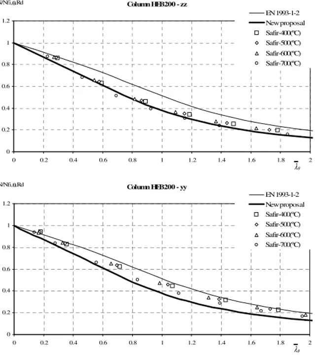
Although it is more accurate, to avoid the use of an imperfection factor depending on the temperature, it is proposed to use equation (11) with ε defined by equation (6) and
0 . 1 =
β . This proposal is called “New proposal” and is shown in figure 4.
Column HEB200 - zz 0 0.2 0.4 0.6 0.8 1 1.2 0 0.2 0.4 0.6 0.8 1 1.2 1.4 1.6 1.8 2 N/Nfi,θ,Rd EN 1993-1-2 New proposal Safir-400(ºC) Safir-500(ºC) Safir-600(ºC) Safir-700(ºC) θ λ Column HEB200 - yy 0 0.2 0.4 0.6 0.8 1 1.2 0 0.2 0.4 0.6 0.8 1 1.2 1.4 1.6 1.8 2 N/Nfi,θ,Rd EN 1993-1-2 New proposal Safir-400(ºC) Safir-500(ºC) Safir-600(ºC) Safir-700(ºC) θ λ
Fig. 4 – Proposed buckling curves for the duplex.
3. DUPLEX BEAM-COLUMN DESIGN IN CASE OF FIRE
In this section a study of the fire resistance of duplex stainless steel beam-columns is made. It is shown an evaluation of the performance of the interaction curves obtained with part 1.2 of Eurocode 3 [10], this study concluded that these interaction curves don’t provide a good approximation to the numerical results obtained with SAFIR. Therefore it was necessary to find other curves that could fit better these numerical results.
The proposal made in section 2 of this paper for the fire resistance of duplex stainless steel columns will be taken into account and the letters “NP” will be added to the legend of the charts when it is used.
3.1 Eurocode 3 proposals for fire situation
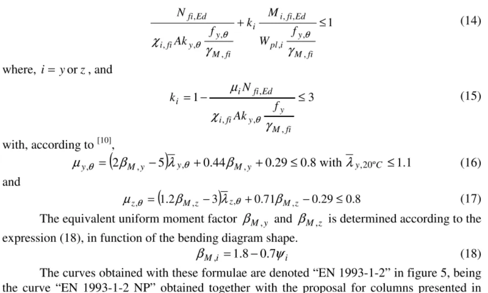
The Eurocode 3 states that the safety evaluation should be made with the same expressions used in carbon steel elements, which are
1 , , , , , , , , , , ≤ + fi M y i pl Ed fi i i fi M y y fi i Ed fi f W M k f Ak N γ γ χ θ θ θ (14) where, i=yorz, and 3 1 , , , , ≤ − = fi M y y fi i Ed fi i i f Ak N k γ χ μ θ (15) with, according to [10],
(
2 , 5)
, 0.44 , 0.29 0.8with ,20º 1.1 , = M y − y + M y + ≤ y C ≤ y β λ β λ μ θ θ (16) and(
1.2 , 3)
, 0.71 , 0.29 0.8 , = M z − z + M z − ≤ z β λ β μ θ θ (17)The equivalent uniform moment factor βM ,y and βM ,z is determined according to the expression (18), in function of the bending diagram shape.
i i
M ψ
β , =1.8−0.7 (18)
The curves obtained with these formulae are denoted “EN 1993-1-2” in figure 5, being the curve “EN 1993-1-2 NP” obtained together with the proposal for columns presented in section 2..
N+My buckling around the y-y-axis L=4000mm; λy,θ =0.329
N+Mz buckling around the z-z-axis L=2000mm; λz,θ =0.545 600 ºC 0 0.2 0.4 0.6 0.8 0 0.2 0.4 0.6 0.8 1 M/Mfi,Rd N/Nfi,Rd SAFIR EN 1993-1-2 EN 1993-1-2 NP 600 ºC 0 0.2 0.4 0.6 0.8 0 0.2 0.4 0.6 0.8 1 M/Mfi,Rd N/Nfi,Rd SAFIR EN 1993-1-2 EN 1993-1-2 NP
Fig. 5 – Beam-column interaction curves for ψ=1.
From figure 5 it can be concluded that the interaction curves, obtained with the new proposal for columns presented in section 2, are too conservative.
3.2 Proposal for the design of duplex beam-column in case of fire
Based in the same procedure adopted by Talamona [11], new factors μy and μz to be
(
1.27 , −2.68)
, +0.44 , +0.13≤0.8 = M y y M y y β λ β μ θ (19)(
1.17 , −2.66)
, +0.64 , −0.01≤0.8 = Mz z Mz z β λ β μ θ (20)Figure 6 shows the evolution of μθ as a function of the slendernessλθ for the strong and weak axis..
In this figure, “Average” corresponds to the average of the numerical results obtained with SAFIR, and the curve “New proposal” corresponds to the use of equations (19) and (20). These equations were developed to be a good approximation of the points “Average”.
-3 -2.5 -2 -1.5 -1 -0.5 0 0.5 1 1.5 2 2.5 0 0.5 1 1.5 2 μ Safir EN 1993-1-2 Average New Proposal θ λ Strong axis ψ=1 -3.5 -3 -2.5 -2 -1.5 -1 -0.5 0 0.5 1 0 0.5 1 1.5 2 μ Safir EN 1993-1-2 Average New Proposal θ λ Weak axis ψ=1 -0.6 -0.4 -0.2 0 0.2 0.4 0.6 0.8 1 1.2 1.4 1.6 0 0.5 1 1.5 2 μ Safir EN 1993-1-2 Average New Proposal θ λ Strong axis ψ=0 -1 -0.5 0 0.5 1 1.5 2 2.5 0 0.5 1 1.5 2 μ Safir EN 1993-1-2 Average New Proposal θ λ Weak axis ψ=0 0 0.5 1 1.5 2 2.5 0 0.5 1 1.5 2 μ Safir EN 1993-1-2 Average New Proposal θ λ Strong axis ψ=-1 0 0.5 1 1.5 2 2.5 0 0.5 1 1.5 2 μ Safir EN 1993-1-2 Average New Proposal θ λ Weak axis ψ=-1
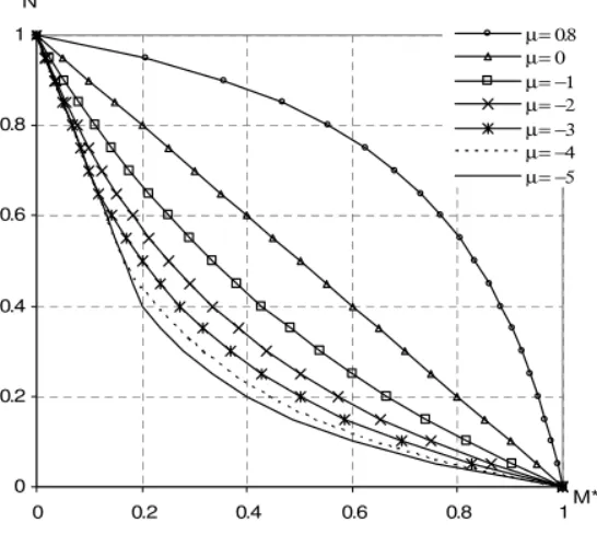
The interaction curve given by (14) and (15) can be written in the following schematic way if bending is only around one axis (weak or strong).
* * * * 1 N +M −μN M = (9) Where fi M y i pl Ed fi i fi M y y fi i Ed fi f W M M f Ak N N , , , , , * , , , , , * and γ γ χ θ θ θ = = (9)
Figure 7 shows the shape of the interaction curves for different values of the coefficient . It is concave for positive values of (meaning that higher resistance is available) and turns convex with negative values of (meaning that lower resistance is available). The short linear branch near the N* axis comes from the limitation of ki =1−μN* to the value of 3 in equation (15).
0 0.2 0.4 0.6 0.8 1 0 0.2 0.4 0.6 0.8 1M * N * μ = 0.8 μ = 0 μ = −1 μ = −2 μ = −3 μ = −4 μ = −5
Fig. 7 – Interaction curves.
Figure 8 compares the interactions curves obtained with the Eurocode 3 and with the proposal made in this paper, for only one length of the beam-column for each buckling direction.
From this figure it can be concluded that the new proposal for duplex beam-columns presents good approximation to the numerical results, being safer then the Eurocode 3.
For bi-triangular bending moment distribution (ψ =−1) the curves denoted “EN 1993-1-2” and EN 1993-1-2 NP” are coincident.
4. CONCLUSIONS
In this paper new proposals, for the flexural buckling resistance of stainless steel columns and for beam-columns under fire loading were proposed. A new imperfection factor that takes into account the influence of the steel grade, and the variation of the yield strength with the temperature, has been proposed being in good agreement with the numerical results obtained with the program SAFIR.
N+My buckling around the y-y-axis L=4000mm;
λ
y,θ =0.329N+Mz buckling around the z-z-axis L=2000mm;
λ
z,θ =0.545 600 ºC 0 0.2 0.4 0.6 0.8 0 0.2 0.4 0.6 0.8 1 M/Mfi,Rd N/Nfi,Rd SAFIR EN 1993-1-2 EN 1993-1-2 NP New proposal ψ=1 600 ºC 0 0.2 0.4 0.6 0.8 0 0.2 0.4 0.6 0.8 1 M/Mfi,Rd N/Nfi,Rd SAFIR EN 1993-1-2 EN 1993-1-2 NP New proposal ψ=1 600 ºC 0 0.2 0.4 0.6 0.8 0 0.2 0.4 0.6 0.8 1 M/Mfi,Rd N/Nfi,Rd SAFIR EN 1993-1-2 EN 1993-1-2 NP New proposal ψ=0 600 ºC 0 0.2 0.4 0.6 0.8 0 0.2 0.4 0.6 0.8 1 M/Mfi,Rd N/Nfi,Rd SAFIR EN 1993-1-2 EN 1993-1-2 NP New proposal ψ=0 600 ºC 0 0.2 0.4 0.6 0.8 0 0.2 0.4 0.6 0.8 1 M/Mfi,Rd N/Nfi,Rd SAFIR EN 1993-1-2 EN 1993-1-2 NP New proposal ψ= -1 600 ºC 0 0.2 0.4 0.6 0.8 0 0.2 0.4 0.6 0.8 1 M/Mfi,Rd N/Nfi,Rd SAFIR EN 1993-1-2 EN 1993-1-2 NP New proposal ψ= -1It should be pointed out that as the parametric study shown in this paper contemplates only few cases, more studies considering other cross sections should be made to check the accuracy of the presented proposals.
ACKNOWLEDGEMENTS
The authors wish to acknowledge the Calouste Gulbenkian Foundation (Portugal) for its supports through the scholarship given to the first authors.
REFERENCES
[1] Euro Inox and Steel Construction Institute, “Design Manual for Structural Stainless Steel”, 3rd edition, 2006.
[2] European Committee for Standardisation, “prEN 1993-1-4 Eurocode 3, Design of Steel Structures – Part 1.4. General rules – Supplementary Rules for Stainless Steels”, Brussels, Belgium, 2005.
[3] European Committee for Standardisation, “EN 1993-1-2 Eurocode 3: Design of Steel Structures - Part 1.2: General rules - Structural fire design”, Brussels, Belgium, April 2005. [4] Lopes, N., Vila Real, P., Silva, L., Franssen, J.-M., Mirambell, E., “Numerical modelling of axially loaded stainless steel members under fire conditions”, proceedings of the International Colloquium on Stability and Ductility of Steel Structures, SDSS’06, vol. 2, pp. 797 a 802, ISBN 972-8469-61-6, Lisboa, Portugal, 6 to 8 of September of 2006.
[5] Franssen, J.-M., “SAFIR. A Thermal/Structural Program Modelling Structures under Fire”, Engineering Journal, A.I.S.C., Vol. 42, No. 3, pp. 143-158, 2005.
[6] Lopes, N., Vila Real, P.M.M., Piloto, P., Mesquita, L.; Simões da Silva, L., “Modelação numérica da encurvadura lateral de vigas I em aço inoxidável sujeitas a temperaturas elevadas”, (in portuguese) Congreso de Métodos Numéricos en Ingeniería, Granada, Spain, 2005.
[7] Chen, W. F. and Lui, E. M., “Stability design of steel frames”, CRC Press, 1991.
[8] Gardner, L., Nethercot, D. A., “Numerical Modeling of Stainless Steel Structural Components - A consistent Approach”, Journal of Constructional Engineering, ASCE, pp. 1586-1601, 2004.
[9] European Committee for Standardisation, “EN 1993-1-1, Eurocode 3, Design of Steel Structures – part 1-1. General rules and rules for buildings”, Brussels, Belgium, 2005.
[10] Talamona, D., Franssen, J.-M., Schleich, J.-B., Kruppa, J., “Stability of Steel Columns in Case of Fire: Numerical Modeling”, Journal of Structural Engineering, 1997.
[11] Talamona, D., “Flambement de poteaux métalliques sous charge excentrée, à haute température”, (in french); Ph.D. thesis, Université Blaise Pascal Ecole Doctorale Sciences pour l’Ingenieur de Clermont-Ferrand, 1995.