People’s Democratic Republic of Algeria
Ministry Of Higher Education and Scientific Research
FINAL YEAR PROJECT REPORT
Presented at
The university of Echahid Hamma Lakhdar El Oued
Faculty of Technology
Department Of Electrical Engineering
Submitted In Fulfillment of the requirement for The Degree Of
MASTER ACADEMIQUE
In Commande Electrique
By
Khechiba Kamel & Khiter Anissa
Title
Design and implementation of microcontroller
based controller for direction and speed of a
robot
Defended on May 25th, 2016. Before the jury:
Mr. Hima Abdelkader…. Maitre de conférences Persident
Mr. Tir Zoheir… Maitre de conférences Supervisor
Mr. Bekakra Youcef…. Maitre de conférences Member
Mr. Majouri Abdelkader Maitre de conférences Invited
N° d'ordre : ……. N° de série : …….
Acknowledgement
We would like to take this opportunity to express our gratitude to our respected supervisor Doctor Tir Zoheir associated professor at the university for the inspired guidance, insight, continuous encouragement, timely suggestions that he has provided throughout the duration of this work. The present work, being successfully completed due to his sincere monitoring and vital inputs.
We would also thank all our friends, faculty and staff members of the Department of Electrical Department for their support and all kinds
ءادــــــــــــــــــــــهإ
ىلإ عضاىتملا لمعلا اره يدهن
داىــــــــــج اندابكأ ثارلف
-ســـــــــــنأو تشئاــــــــــــــع ةءاسب
تبطاق تيملاسلإا تملأا مهب الله عفن
هيلع زداقلاو كلذ ًلو ىهف
نيمآ
نيمآ
𝐴 area of cross section of conductor
D Duty cycle
DC Direct current
emf= Eb Electromotive force= back voltage or counter
Ia Curent armature IR Infra Red IC Integrated Circuit GND Ground Kp proportional gain Ki Integral gain Kd derivative gain
LDR Light Depending Resistor LED Light Emetting Diode
𝑁 The speed in rpm
𝑃 no of pole pairs PWM Pulse Width Modulation
Ra Armature resistance
t Time or instantaneous time Vavg Average signal
𝑍 no of conductors supply voltage 𝐸𝑏 ∅ flux per pole armature
List of figures
Part I:
Fig 2.1 Process under control……… 06
Fig 2.2 General Block Diagram of open-loop system……….. 07
Fig 2.3 General Block Diagram of closed-loop system……… 08
Fig 2.4 Parts of an electric motor………. 10
Fig 2.5 Diagrams of brushed and brushless DC motors………... 12
Fig 2.6 DC motor speed v/s supply voltage……….. 14
Fig 2.7 Duty cycle representation………. 14
Fig 2.8 PWM with various Duty cycles……… 15
Fig 3.1 The board of the ARDUINO UNO R3 20 Part II: Fig 4.1 Block diagram of the autonomous robot……….. 30
Fig 4.2 Sensor circuit diagram……… 30
Fig 4.3 Types of Light dependant resistor………. 31
Fig 4.4 Position of an LDR with a LED……… 31
Fig 4.5a Circuit diagram of comparator IC………. 32
Fig 4.5b The LM324 (comparator) pins connections………. 32
Fig 4.6 Comparator connection with IR sensor………. 33
Fig 4.7 An H-bridge for 3 volt power supplies………. 35
Fig 4.8 An H-bridge schematic……….. 36
Fig 4.9 The L293D IC configuration……… 37
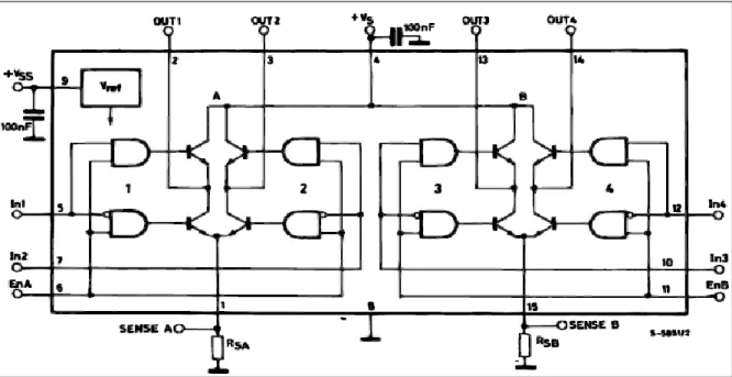
Fig 4.10 Block Diagram of an L298………... 39
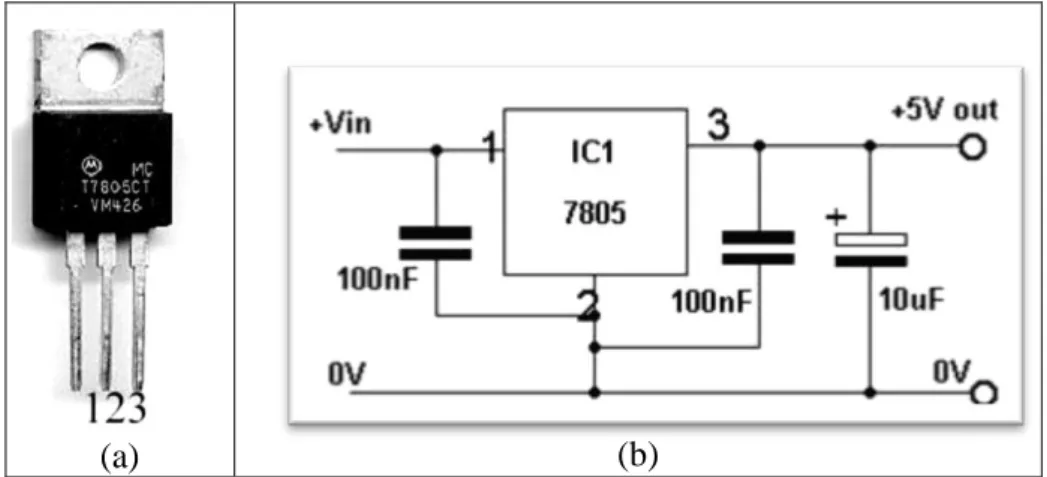
Fig 4.11 The 7805 IC and its connection……… 41
Fig 4.12 The connection circuitry of the ARDUINO,L298N with 2 DC Motors……….. 42
Fig 4.13 Beginning of simulation (forward direction)……… 50
Fig 4.14 Enable A and Enable B goes HIGH………. 51
Fig 4.15a One of the two LDR become closer to the black line……….. 51
Fig 4.15b The deference in the speed between the two DC Motors………. 52
Fig 4.13 The voltage applied between the two terminals of the DC Motors…………... 53
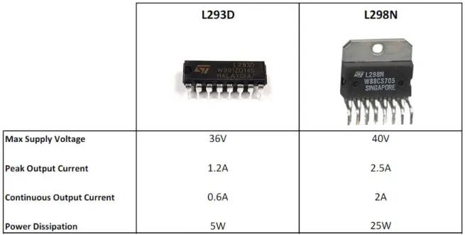
Tab 4.1 The comparison between L293D and L298N……… 40
TABLE OF CONTENTS Acknowledgements ……….. i Dedication ……….. ii Nomenclature ……….. iii List of Figures ……….. iv Table of contents ……….. v Abstract ……….. vi
Thesis organization ………. vii
Part I : THEORETICAL BACKGROUND Chapter 1 : Introduction to robotic 1. Introduction……….. 01 2. Characteristics of robot……..……….. 02 3. Types of robots………. 02 3.1. Mobile robots ……….... 03 3.2. Industrial robots………... 03 3.3. Autonomous robots………. 03 3.4. Remote-controlled robots.……….. 03 3.5. Virtual robots………..……… 04 4. Applications of robot……… 04
5. Applications of line follower robot……….. 05
6. Conclusion ………..…... 05
Chapter 2 : Control of DC motors 1. Introduction……….. 06
2. Control system theory………... 06
2.1. Open loop control………... 07
2.1.1. Open loop characteristics……….. 07
2.2. Closed loop control…….………... 08
2.2.1 Closed loop characteristics……… 08
2.3. Difference between open loop and closed loop operation of DC motor. 09 3. DC motor ……….……… 09
3.1. Factors controlling motor speed …….………... 10
3.1.1. Applied voltage control……….. 10
3.1.2 Armature rheostat control………... 11
3.1.3. Flux control……… 11
4. Characteristics………. 11
5. DC motor types……… 11
6. Controlling the speed of brushed DC motor……… 13
7. DC motor speed controller (PWM of ARDUINO)………. 13
8. Duty cycle (D)………. 14
9. PWM generator……… 16
6. The board……….. 2 0 6.1. Power……….. 2 1 6.2. The memory... 2 1
6.3. Input and output………. 2
1 6.4. Communication………... 2
3 6.5. USB Over current protection……….. 2
3 6.6. Automatic (software) reset………. 2
3 7. Interface architecture……… 2 3 8-Microcontroller programs………. 2 4 9. Background-information for the Arduino software……….. 2 5 10. Software………. 2 6 11. Language reference……… 2 6 12. Conclusion………. 2 8 Part II Chapte r 4 Simulation, Design and implementation 1. Introduction……….. 2
9 2. Design of the robot……….. 2
9 2.1. Basic operation……….. 2
9 2.2. Basic design and requirements………... 2
9 2.3 The input system………. 3
0 2.3.1. Sensors………. 3
0 2.3.2. Comparator……….. 3
Chapter 3 : Microcontroller (Arduino) 1. Introduction……….. 17
2. History of ARDUINO... 17
3. Types of Arduino……… 17
4. The Arduino uno……… 19
2 2.3.2.1. The use of comparator in IR
sensor……… 3 3 2.4. Processing system……… 3 3 2.5. The output system……… 3 4 2.5.1. Motor output system……….. 3 4
2.5.2. The motor drive……… 3
4 2.5.3. Background-information to the h-bridge circuits………. 3
5 2.5.4. An H-bridge for 3 volt power supplies………. 3
5
2.5.5 The L293D IC drive (an H-bridge for 4.5 V)……… 3 7 2.5.6. The l298 IC driver (dual full-bridge driver)………. 3
9 2.5.7. Application information……… 3
9 2.5.8. The comparaison between the two ICs………. 4
0 2.5.9. The 1N4007 Shottkey diode……….. 4 0 2.5.10. Voltage regulator 78xx……… 4 0 2.6. Summary……… 4 1 3. Implementation………. 4 2 3.1. Introduction……… 4 2 3.2. Circuit connections………... 4 3 3.4. Navigation………... 4 1
3.5. Algorithm for robot………. 4
3 3.5.1. Flowchart explanation………... 4 6 3.6. Summary………. 4 8 4. Simulation……….. 4 9 4.1. Introduction to PROTEUS………. 4 9
4.2 What is Proteus design suite……….. 4 9 4.3. Beginning of simulation………. 5
0 4.4 Summary……….. 5 3 Conclusion ……….. 5 4 Reference……… … 5 5 Annexe 1. Datasheet of the L298N 2. Datasheet of the 7805 3. Datasheet of the 1N4007
ABSTRACT
Today we find most robots working for people in industries, factories, warehouses, and laboratories. Robots are useful in many ways. For instance, it boosts economy because businesses need to be efficient to keep up with the industry competition.
Line Following is one of the most important aspects of robotics. This project aims to design and implement a closed loop control system by algorithm using feedback mechanism to control the movement of the robot by the use of three pair of photo sensors, comprising of one IR transmitter and a photo diode in each. It guides the robot by giving appropriate signal to the microcontroller to follow a line that is drawn on the floor. The path consists of a black line on a white surface (or it may be reverse of that). Two DC motors are used interfaced to the microcontroller through a motor driver IC. Input signals given to the microcontroller from the sensors and then the controller takes the appropriate action according to the program written in it and drives motors as desired.
Thesis Organization:
This thesis is a documentary delivering the ideas generated, concepts applied, activities done and finally the final year project. It contains four chapters in two main parts. The following is a description of information in this thesis.
Chapter 1
Provides a general overview of the project and the use and importance of different kinds of industrial robot, such that the autonomous robots in the world.
Chapter 2
Describes the control systems used in the industrial process such that the open and the closed loop system which we are used in this project by using an algorithm as a feedback control to minimize the error occurred between the desired value and the output given by the motion of the robot. We give also an overview on the DC motors used, and the PWM generated by the microcontroller.
Chapter 3
We deal in this chapter on the brain of the robot which is the microcontroller (the ARDUINO UNO), its characteristics, the essential pins, and their connections with the other devices used in the implementation of the robot such that the driver L298N.
Chapter 4
Describe the hardware development unit in line following robot. This chapter describes about sensor arrays, microcontroller, motor driving system. It also describes the project methodology and explains hardware development for the design of the robot. Simulation with the PROTEUS has also been covered in this chapter. Also it contains all the results obtained from the software experiments that include the algorithm implemented in a program.
Finally, chapter 4 will summarize the final year project. The conclusion, suggestions or recommendations for improvements that can be implemented in future are discussed within this chapter.
1. Introduction:
A Robot has been defined by the Robot Institute of America as:
“A robot is a reprogrammable, multifunction, manipulator designed for moving materials, tools, parts etc. through various programmed motions to perform a variety of tasks “. A Robot has been defined by Webster dictionary as:
“A robot is an automatic device that performs functions normally ascribed to humans or a machine in the form of a human.”
A Robot is any machine which is completely automatic, i.e. it starts on its own, decides its own way of work and stops on its own. It is actually a replica of human being, which has been designed to ease human burden. It can be controlled pneumatically or using hydraulic ways or using the simple electronic control ways. The first industrial robot was Unimates built by
George Devol and Joe Engelberger in the late 50‟s and early 60‟s. Generally robots have three main parts which include processor, sensor and motor control system. Robot sensors represent eyes while actuators act as legs and controller acts as the brain of a human.
Robots can be fixed robots or mobile robots. Mobile Robots are robots with a mobile base which makes the robot move freely in the environment. One of the advanced mobile robots is the Line Follower Robot. It is basically a robot which follows a particular path or trajectory and decides its own course of action which interacts with obstacle. The path can be a black line on the white floor (visible) or a magnetic field (invisible). Its applications start from basic domestic uses to industrial uses, etc. The present condition in industry is they are carrying the parcels or materials one place to another place using the crane system. Sometimes lifting of big weights at that time may cause the breakage of lifting materials and will be cause damage to the parcels also. The line following robots is commonly used for carry children through shopping malls, homes, entertainment places, industries. The use of line following robotic vehicle is transport the materials from one place to another place in the industries. This robot movement completely depends on the track. The robot can do anything you set them to do. Like in factories all they have to do with making their products is make the robot. [8]
2. Characteristics of robot:
As strange as it might seem, there really is no standard definition for a robot. However, there are some essential characteristics that a robot must have:
Sensing First of all your robot would have to be able to sense its surroundings. It
would do this in ways that are not similar to the way that you sense your surroundings. Giving your robot sensors: light sensors (eyes), touch and pressure sensors (hands), chemical sensors (nose), hearing and sonar sensors (ears), and taste sensors (tongue) will give your robot awareness of its environment.
Movement A robot needs to be able to move around its environment. Whether rolling
on wheels, walking on legs or propelling by thrusters a robot needs to be able to move. To count as a robot either the whole robot moves, like the Sojourner or just parts of the robot moves, like the Canada Arm.
Energy A robot needs to be able to power itself. A robot might be solar powered,
electrically powered, battery powered. The way your robot gets its energy will depend on what your robot needs to do.
Intelligence A robot needs some kind of "smarts." This is where programming enters
the pictures. A programmer is the person who gives the robot its 'smarts.' The robot will have to have some way to receive the program so that it knows what it is to do. [6]
3. Types of robots:
The types of robots are: 1) Mobile robots. 2) Industrial robots 3) Autonomous robots 4) Remote-controlled robots. 5) Virtual robots.3.1. Mobile robots:
Mobile robots are able to move; usually they perform tasks such as searching. They are of 2 types:
1) Rolling robots- Rolling robots have wheels to move around. They can quickly and easily search. However they are only useful in flat areas.
2) Walking robots- Robots on legs are usually brought in when the terrain is rocky. Most robots have at least 4 legs; usually they have 6 or more.[7]
3.2. Industrial robots:
Most of these robots perform repeating tasks without ever moving. Most robots are working in industries. Especially dull and repeating tasks are suitable for robots. A robot never grows tired; it will perform its duty day and night without ever complaining. [7]
3.3. Autonomous robots:
Autonomous robots are the robots that can perform desired tasks in any environment without continuous human guidance. In fields like space exploration high degree of autonomy is required where communication and delays are unavoidable.
In the real world a fully autonomous robot has the ability to gain information about the environments and to work for months without human intervention. It can travel from one location to the other without navigation assistance. It can avoid situations that are harmful to any property or itself and can repair without external assistance. [8]
3.4. Remote-controlled robots:
Complicated tasks are still best performed by human beings with real brainpower. A person can guide a robot by remote control. A person can perform difficult and usually dangerous tasks without being at the spot where the tasks are performed. [7]
3.5. Virtual Robots:
Virtual robots don‟t exist in real life. Virtual robots are just programs, building blocks of software inside a computer. A virtual robot can simulate a real robot or just perform a
repeating task. Search engines use such kind of robots. They search the World Wide Web and send the information to the search engines. [7]
4. Applications of a robot:
Robot can replace human‟s job because robots can perform faster than humans. Robots need not to drink, to be paid or rest as compared to humans. They can do repetitive work with high accuracy and will not stop or slow until the task is finished while humans get bored. Robot can be applied in military to reducing the number of casualties which occur during military actions has been already been prioritized. The military also uses robots for locating and destroying mines on land and in water, spying on enemies and entering enemy bases for gathering information.
Nowadays a doctor can use robots while performing surgery. A human would not be able to make a whole exactly one 100th of an inch wide and long. When making medicines, robots can perform their job much faster and much accurately and delicate in comparison to humans. Doctors and engineers sometimes are developing prosthetic limbs by using robotic mechanisms.
Individual stationary sensors have limited ranges and applications. Watchdogs and humans can lose their level of alertness during shift and be injured by intruders. Autonomous robot systems are the tools that combine the precision of sensors with the mobility and intelligence of humans.
Robotic site of security sentries are able to work for long hours at consistency high level of vigilance and precision. People are interested in places full of danger like outer space or under seas. They cannot go themselves there so they use robots which are used for exploration.
The robots can carry cameras and other instruments through which they can collect information and send back for processing to their human operators. The continuous development of autonomous robots increases our ability to explore universe. [8]
5. Applications of line follower robot:
Industrial Applications: These robots can be used as automated equipment carriers in
industries replacing traditional conveyer belts.
Automobile applications: These robots can also be used as automatic cars running on
Domestic applications: These can also be used at homes for domestic purposes like
floor cleaning etc.
Guidance applications: These can be used in public places like shopping malls,
museums etc to provide path guidance. [8]
6. Conclusion:
A robot is a system that contains sensors, control systems, manipulators, power supplies and software all working together to perform a task. Designing, building, programming and testing a robot is a combination of physics, mechanical engineering, electrical engineering, structural engineering, mathematics and computing. In some cases biology, medicine, chemistry might also be involved. A study of robotics means that students are actively engaged with all of these disciplines in a deeply problem-posing problem-solving environment. [6]
1. Introduction:
DC Motor plays a crucial role in research and laboratory experiments because of their simplicity and low cost. The speed of the motor can be controlled by three methods namely terminal voltage control, armature rheostat control method and flux control method. Here in this project terminal voltage control method is employed.
A control system is an interconnection of components forming a system configuration that will provide a desired system response. A controlled DC-motor was developed allowing ARDUINO hardware acts as the interface between the computer and the outside world. It primarily functions as a device that digitizes incoming analog signals so that the computer can interpret them. The user interface was developed in an ARDUINO environment. [5]
2. Control system theory:
The control system is that means by which any quantity of interest in a machine, mechanism or other equipment is maintained in accordance with a desired manner. [5] All our tools and machines need appropriate control to work; otherwise it will be difficult to finish their designated tasks accurately. Therefore, we need control systems to guide, instruct and regulate our tools and machines. Common control systems include mechanical, electronic, pneumatic and computer aided. A component or process to be controlled can be represented by a block as shown in Figure 2.1. [12]
Fig 2.1:
Process under control [12]
Plant: The plant is also known as the process and it is the physical system to be controlled.
Output or the Controlled Variable: It is the signal or the plant output which we need to control. In our case the speed of the DC Motor is the controlled variable which is to be control.
Reference: It is the desired value that we want to see at the output. In this thesis set point or reference is the desired speed of the DC Motor.
There are basically two types of control system: the open loop system and the closed loop system. They can both be represented by block diagrams.
2.1. Open loop control:
Any physical system which does not automatically correct for variation in its output is called an open-loop system. In these systems the output remains constant for a constant input signal provided the external conditions remain unaltered. The output may be changed to any desired value by approximately changing the input signal but variations in external conditions may cause the output to vary from the desired value in an uncontrollable fashion Examples of the open loop control systems include washing machines, light switches, gas etc. [5] [12].
Fig 2.2 General Block Diagram of open-loop system [5]
2.1.1. Open-loop characteristics
[5]:
Shows an open-loop action (controlled chain);
Can only counteract against disturbances, for which it has been designed; other disturbances cannot be removed;
Cannot become unstable - as long as the controlled object is stable.
2.2. Closed loop control:
Feedback is a special feature of a closed loop control system. A closed loop control system compares the output with the expected result or command status, and then it takes appropriate control actions to adjust the input signal. Therefore, a closed loop system is always equipped with a sensor, which is used to monitor the output and compare it with the expected result. The output signal is fed back to the input to produce a new output. A well-designed feedback system can often increase the accuracy of the output.
Feedback can be divided into positive feedback and negative feedback. Positive feedback
causes the new output to deviate from the present command status. Negative feedback directs the new output towards the present command status, so as to allow more sophisticated control. Most modern appliances and machinery are equipped with closed loop control systems. Examples include air conditioners, refrigerators, etc[12]
Fig 2.3: General Block Diagram of closed-loop system [5]
2.2.1. Closed-loop characteristics [5]:
Shows a closed-loop action (closed control loop);
Can counteract against disturbances (negative feedback);
Can become unstable, i.e. the controlled variable does not fade away, but grows (theoretically) to an infinite value.
2.3. Difference between open loop and closed loop operation of DC
motor:
In open loop control of DC Motor the output (speed of the motor) cannot be maintained at a desired value due to external disturbances and system variables, whereas in closed loop operation the output can maintained due to the presence of feedback circuit. Feedback circuit samples the output and gives signals to the error detector which compares the feedback signal with the specified value and produces a modified signal according to the output.[5]
3. DC motor:
A DC motor is a machine that converts electrical energy into mechanical energy. The operation is based on simple electromagnetism, “when a current carrying conductor is placed
in an external magnetic field it experiences a force which is proportional to the current and the external magnetic field.” A torque is generated by the magnetic reaction and the armature revolves and this induces a voltage in the armature windings which is opposite in direction to the outside voltage applied to the armature, when current is passed through the armature of the DC motor, and hence is called back voltage or counter e.m.f. The back voltage rises till it becomes equal to the applied voltage as the motor rotates faster,
The speed at which the DC motor rotates depends on two factors - the armature current as well as the strength of the magnetic field acting on the armature. The stronger the field, the slower is the rotation rate required to produce a back voltage huge enough to counteract the applied voltage. Hence, the speed of the DC motor can be controlled by varying the field current.
Every DC motor consists of six parts: axle, stator, rotor, commutator, field magnet and brushes. [15]
Fig 2.4: Parts of an electric motor[10]
The stator holds the motor casing as well as the two permanent magnets which helps to generate the external magnetic field. The rotor rotates with respect to the stator; it has windings which are electrically connected to the commutator. [5]
The back emf in volt of DC motor :
Where
Ia= Curent armature
The speed of the motor is given by the relation:
Where, Ra = armature resistance andspeed in rpm=
.
3.1. Factors controlling motor speed:
The speed of the motor can be controlled by three methods namely terminal voltage control, armature rheostat control method and flux control method
3.1.1. Applied voltage control:
This type of speed control can be used in separately excited DC motors, where the field supply is connected permanently to a fixed exciting voltage. The armature speed will be approximately proportional to these different voltages. This method is one of the simplest methods of speed control.[5]
3.1.2. Armature rheostat control
:This type of speed control can be used in series, shunt and compound motors. As the supply voltage is kept constant, the voltage across the armature is varied by inserting a variable rheostat in series with the armature circuit.[5]
3.1.2. Flux control
:This type of speed control can be used in shunt and compound motors. In this method, speed is controlled by varying the field current. Flux is directly proportional to field current. By decreasing the flux, the speed can be increased and vice-verse.[5]
4. Characteristics
: [5] Nearly constant speed
Torque varies nearly as the current
Medium starting torque (twice full load torque with twice full load current at start) Continuous speed range 4:1 maximum
𝑁
Medium maintenance cost
5. DC motor types:
There are two main types of DC motors: brushed DC motors and brushless DC motors. Brushed DC motors generate mechanical power by placing a rotatable armature with coils inside of a stationary magnetic field. Brushes and commutators are used to make the current reverse direction multiple times (depending on the number of poles) each cycle. This causes the motor to rotate, creating mechanical power. On the other hand, brushless DC motors do not have brushes or commutators, and generate mechanical power by synchronizing the voltages applied to the driving coils. Figure below shows the basic structure of a simple 2 pole brushed DC motor and a brushless DC motor. [10]
Fig 2.5: Diagrams of brushed and brushless DC motors[10]
There are inherent differences between brushed and brushless DC motors, and it is important to pick the one that is best for our project. Brushed motors are lower cost, much simpler to control, less complex, and more rugged. However, the presences of brushes cause many problems to arise. First of all, the brushes physically rub up against the commutator, causing friction which increases with speed. This rubbing also causes the dissipation of heat, which can be problematic at higher speeds. Also, the brushes wear out over time, requiring periodic maintenance or replacing the motor altogether. On the other hand, brushless motors require less maintenance, are capable of higher speeds, are more efficient than their brushed counterparts, and are capable of being cooled by conduction, allowing for the motor to be sealed off, protecting it from dirt and other stuff that can damage the motor. The downside of brushless motors is that they cost more than brushed motors and require much more complex controls, which can also add to the overall cost. [10]
6. Controlling the speed of brushed DC motor:
For brushed DC motors, speed is proportional to the voltage applied across its terminals. One way to control voltage applied to the DC motor is to use a potentiometer or another type of variable resistor in a voltage divider. Varying the potentiometer would vary the voltage applied, changing the speed of the motor. The problem with this method is that power is dissipated in the resistors, decreasing efficiency.
A better way to control the voltage is to use Pulse Width Modulation (PWM). PWM uses a microcontroller to turn the voltage on and off, effectively changing the average voltage applied to the DC motor. Motor speed is increased by increasing the duty cycle, and is decreased by decreasing the duty cycle. The ARDUINO UNO is capable of PWM for speed control.[10]
7. DC motor speed controller (PWM of ARDUINO):
The function of a DC motor speed controller is to take as input a signal representing the demanded speed and to drive a motor at that speed. The controller may or may not measure the speed of the motor to use it as a feedback for the purpose of error reduction. If it does so, it is called a closed loop system else an open loop system.[15]
The DC motor speed in general is directly proportional to the supply voltage, so if reduce the voltage from 12 volts to 6 volts then our speed become half of what it originally had. But in practice, for changing the speed of a DC motor we cannot go on changing the supply voltage all the time. So how to change the speed of the motor with input voltage fixed led to the development of systems known as speed controllers. [15]
The speed controller for a DC motor works by varying the average voltage supplied to the motor (PWM is one such speed controller were we can get varying voltage according to the duty cycle of the PWM output signal). Rather than simply adjusting the voltage sent to the motor, we can switch the motor supply on and off where switching is done so much fast that the motor only notices the average effect. [15]
The time it takes a motor to speed up slow down under switching conditions depends on the inertia of the motor. The graph below shows the speed of a motor that is switched on and off fairly slowly. If switching is done fast enough the motor does not have time to change spee d and it give s an alm ost cons tant speed. Thus the speed is set by Pulse Width Modulation (PWM). [15]
Fig 2.6: DC motor speed versus supply voltage[15]
8. Duty-cycle (D):
Duty cycle (the width of the signal) is defined as the percentage ratio of the pulse HIGH to pulse HIGH + LOW during a PWM period. or it is a percentage measurement of how long the signal stays on.
Duty Cycle is determined by:
Average signal can be found as:
Usually, VL is taken as zero volts for simplicity.
% 100 Period Time On Cycle Duty
Fig 2.7: Duty cycle representation [16]
The average DC value for a 0% duty cycle is zero; with 25% duty cycle its 1.25(for a 5V DC supply). For 50% the average value is 2.5V and 3.75V for a 75% duty cycle and so on. as shown in Fig 2.8
A longer duty cycle means the voltage is on for longer and the average voltage applied to the motor is higher and vice versa.
Thus by varying the pulse width we can vary the average voltage across the DC motor and hence the speed.[16]
9. PWM generator
:Pulse width modulation is a technique to provide a logic‟0‟ and logic „1‟ for a controlled period of time. Analog voltages and current can be used to control processes directly but as simple it seems it‟s not always practical and economical to do so because analog circuits tend to drift over time and can therefore be very difficult to tune. Controlling an analog circuit digitally can greatly reduce cost as well as power consumption. PWM is a powerful technique for controlling analog circuits digitally.[15]
PWM is a way of digitally encoding analog signal levels. The duty cycle of a square wave can be modulated to encode a specific analog signal level. However the PWM signals are always digitals because at any instant the DC supply is either fully on or fully off. Voltage or current sources are applied to the analog load by means of repeating series of on and off pulses. [15]
The “on-time” is the time during which DC supply is given to load while the “off-time” is the time during which it is switched off. Given a sufficient bandwidth, an analog value can be encoded with PWM. [15]
10. Conclusion
In real PWM speeds control of DC. Motors, the output is switched on and off in a period typically in the range of 50 to 200 microseconds. This extremely fast switching means that the average power applied to the motor can be controlled. The switching happens so fast that the motor does not get sufficient time to slow down to stop during the off (space) times. Instead the motor speed varies depending on the average amount of power applied to it.
1. Introduction:
Arduino is an open source- single board microcontroller, which provides an easy access to programming, microcontrollers and project platforms for interactive objects for artists, designer, hobbyists and others.
The Arduino-platform has been based on an Atmel‟s ATmega168 or ATmega328 microcontroller. The system provides users with digital I/O-ports and analog input channels, which allow the Arduino-system to receive and respond to signals from the environment.
The Arduino system applies a powerful Atmel ATmega328P single chip, providing an 8-bit microcontroller at 16 MHz with 32K bytes In-system programmable flash. The power supply voltage has been designed quite versatile in the range DC7-12V, providing stabilized and protected operating conditions for the chip and isolated power lines up to 2A for motor circuitry.
A microcontroller (sometimes abbreviated μC, uC or MCU) is a small computer on a single integrated circuit containing a processor core, memory, and programmable input/output peripherals. Program memory and a small amount of data memory (RAM) is also often included on chip.
Microcontrollers are used in automatically controlled products and devices, such as automobile engine control systems, implantable medical devices, remote controls, office machines, appliances, power tools, and toys. By reducing the size and cost compared to a design that uses a separate microprocessor, memory, and input/output devices, microcontrollers make it economical to digitally control even more devices and processes. [1]
2. History of arduino:
Originally the Arduino project started 2005 in Ivrea, Italy. The concept aimed to support students in projects, in which the prototyping should be cheaper and more efficient as in most standard methods.
The developer group under Massimo Banzi and David Cuartielles decided to name the project after a historical character named „Arduin of Ivrea‟. “Arduino” is the Italian version of the name, meaning “strong friend”. The English version of the name is “Hardwin”.
The system has been equipped with a compiler for a standardized programming language and a boot-loader. The programming language has been based on Wiring- language, which corresponds to C++. [1]
3. Types of Arduino:
Fifteen versions of the Arduino hardware have been commercially produced to date
1. The Serial Arduino, programmed with a DE-9 serial connection and using an ATmega8
2. The Arduino Extreme, with a USB interface for programming and using an ATmega8 3. The Arduino Mini, a miniature version of the Arduino using a surface-mounted
ATmega168
4. The Arduino Nano, an even smaller, USB powered version of the Arduino using a surface-mounted ATmega168 (ATmega328 for newer version)
5. The LilyPad Arduino, a minimalist design for wearable application using a surface-mounted ATmega168
6. The Arduino NG, with a USB interface for programming and using an ATmega8 7. The Arduino NG plus, with a USB interface for programming and using an
ATmega168
8. The Arduino Bluetooth, with a Bluetooth interface for programming using an ATmega168
9. The Arduino Diecimila, with a USB interface and utilizes an ATmega168 in a DIL28 package (pictured)
10. The Arduino Duemilanove ("2009"), using the ATmega168 (ATmega328 for newer version) and powered via USB/DC power, switching automatically
11. The Arduino Mega, using a surface-mounted ATmega1280 for additional I/O and memory.
12. The Arduino Uno uses the same ATmega328 as late-model Duemilanove, but whereas the Duemilanove used an FTDI chipset for USB, the Uno uses an ATmega8U2 programmed as a serial converter.
13. The Arduino Mega2560, uses a surface-mounted ATmega2560, bringing the total memory to 256 kb. It also incorporates the new ATmega8U2 (ATmega16U2 in revision 3) USB chipset.
14. The Arduino Leonardo, with an ATmega32U4 chip that eliminates the need for USB connection and can be used as a virtual keyboard or mouse. It was released at the Maker Faire Bay Area 2012.
15. The Arduino Esplora, resembling a video game controller, with a joystick and built-in sensors for sound, light, temperature, and acceleration.
4. The arduino uno:
The Arduino Uno is a microcontroller board based on the ATmega328 .It has 14 digital input/output pins (of which 6 can be used as PWM outputs), 6 analog inputs, a 16 MHz crystal oscillator, a USB connection, a power jack, an ICSP header, and a reset button. It contains everything needed to support the microcontroller; simply connect it to a computer with a USB cable or power it with a AC-to-DC adapter or battery to get started. The Uno differs from all preceding boards in that it does not use the FTDI USB-to-serial driver chip. Instead, it features the Atmega8U2 programmed as a USB-to-serial converter.
"Uno" means one in Italian and is named to mark the upcoming release of Arduino 1.0. The Uno and version 1.0 will be the reference versions of Arduino, moving forward. The Uno is the latest in a series of USB Arduino boards, and the reference model for the Arduino platform. [2]
5. Technical specification:
Microcontroller ATmega328 Operating Voltage 5V
Input Voltage (recommended) 7-12V Input Voltage (limits) 6-20V
Digital I/O Pins 14 (of which 6 provide PWM output) Analog Input Pins 6
DC Current per I/O Pin 40 mA DC Current for 3.3V Pin 50 mA
Flash Memory 32 KB of which 0.5 KB used by boot loader SRAM 2 KB
EEPROM 1 KB Clock Speed 16 MHz
6.The board:
Fig 3.1: The board of the ARDUINO UNO R3.[3]
6.1.Power:
The Arduino Uno can be powered via the USB connection or with an external power supply. The power source is selected automatically.
External (non-USB) power can come either from an AC-to-DC adapter (wall-wart) or battery. The adapter can be connected by plugging a 2.1mm center-positive plug into the board's power jack. Leads from a battery can be inserted in the GND and Vin pin headers of the POWER connector.
The board can operate on an external supply of 6 to 20 volts. If supplied with less than 7V, however, the 5V pin may supply less than five volts and the board may be unstable. If using
more than 12V, the voltage regulator may over heat and damage the board. The recommended range is 7 to 12 volts.[2] .[3]
The power pins are as follows:
VIN. The input voltage to the Arduino board when it's using an external power source (as opposed to 5 volts from the USB connection or other regulated power source). You can supply voltage through this pin, or, if supplying voltage via the power jack, access it through this pin.
5V. The regulated power supply used to power the microcontroller and other
components on the board. This can come either from VIN via an on-board regulator, or be supplied by USB or another regulated 5V supply.
3V3. A 3.3 volt supply generated by the on-board regulator. Maximum current draw is 50 mA.
GND. Grounds pins.
6.2. Memory:
The Atmega328 has 32 KB of flash memory for storing code (of which 0,5 KB is used for the boot loader); It has also 2 KB of SRAM and 1 KB of EEPROM (which can be read and written with the EEPROM library).[2]
6.3. Input and output:
Each of the 14 digital pins on the Uno can be used as an input or output, using pinMode(), digitalWrite(), and digitalRead() functions. They operate at 5 volts. Each pin can provide or receive a maximum of 40 mA and has an internal pull-up resistor (disconnected by default) of 20-50 k Ohms. [2]
In addition, some pins have specialized functions: Serial: 0 (RX) and 1 (TX).
Used to receive (RX) and transmit (TX) TTL serial data. These pins are connected to the corresponding pins of the ATmega8U2 USB-to-TTL Serial chip.
External Interrupts: 2 and 3. These pins can be configured to trigger an interrupt on a low value, a rising or falling edge, or a change in value.
SPI: 10 (SS), 11 (MOSI), 12 (MISO), 13 (SCK).
These pins support SPI communication, which, although provided by the underlying hardware, is not currently included in the Arduino language.
LED: 13. There is a built-in LED connected to digital pin 13. When the pin is HIGH value, the LED is on, when the pin is LOW, it's off.
The Uno has 6 analog inputs, each of which provides 10 bits of resolution (i.e. 1024 different values). By default they measure from ground to 5 volts, though is it possible to change the upper end of their range using the AREF pin and the analogReference ( ) function. Additionally, some pins have specialized functionality:
I2C: 4 (SDA) and 5 (SCL). Support I2C (TWI) communication using the Wire library.
AREF. Reference voltage for the analog inputs. Used with analogReference ().
Reset. Bring this line LOW to reset the microcontroller. Typically used to add a reset button to shields which block the one on the board.
PWM: An Arduino Uno has 14 digital input/output (I/O) pins1. Conventional, i.e., not PWM, operation of the digital I/O pins is controlled with the pinMode, digitalRead and digitalWrite functions.
The pinMode function is used to configure a pin as an input or output.
When a digital I/O pin is configured as an input, digitalRead reads the state of the pin, which will be either HIGH or LOW.
In an Arduino sketch, HIGH is a predefined constant that is evaluated as "true" in a conditional expression, and is equivalent to a numerical value of 1. Electrically, a value of HIGH means the pin voltage is close to 5 V. Similarly, the constant LOW is interpreted as "false" in conditional expressions, it is numerically equivalent to 0, and electrically the pin voltage is 0. When a digital I/O pin is configured for output, digitalWrite is used to set the pin voltage to HIGH or LOW.[4]
6.4.Communication:
The Arduino Uno has a number of facilities for communicating with a computer, another Arduino, or other microcontrollers. The ATmega328 provides UART TTL (5V) serial communication, which is available on digital pins 0 (RX) and 1 (TX). An ATmega8U2 on the board channels this serial communication over USB and appears as a virtual com port to software on the computer. The '8U2 firmware uses the standard USB COM drivers, and no external driver is needed. However, on Windows, an *.inf file is required.
The Arduino software includes a serial monitor which allows simple textual data to be sent to and from the Arduino board. The RX and TX LEDs on the board will flash when data is being transmitted via the USB-to serial chip and USB connection to the computer (but not for serial communication on pins 0 and 1).[2]
6.5. USB Over current protection:
The Arduino Uno has a resettable poly fuse that protects your computer's USB ports from shorts and overcurrent. Although most computers provide their own internal protection, the fuse provides an extra layer of protection. If more than 500 mA is applied to the USB port, the fuse will automatically break the connection until the short or overload is removed.[2]
6.6. Automatic (software) reset:
Rather than requiring a physical press of the reset button before an upload, the Arduino Uno is designed in a way that allows it to be reset by software running on a connected computer. One of the hardware flow control lines (DTR) of the ATmega8U2 is connected to the reset line of the ATmega328 via a 100 nano farad capacitor. When this line is asserted (taken low), the reset line drops long enough to reset the chip. The Arduino software uses this capability to allow you to upload code by simply pressing the upload button in the Arduino environment.[2]
7. Interface architecture:
Microcontrollers usually contain from several to dozens of general purpose input/output pins (GPIO). GPIO pins are software configurable to either an input or an output state. When GPIO pins are configured to an input state, they are often used to read sensors or external
signals. Configured to the output state, GPIO pins can drive external devices such as LEDs or motors.
Many embedded systems need to read sensors that produce analog signals. This is the purpose of the analog-to-digital converter (ADC).
Since processors are built to interpret and process digital data, i.e. 1s and 0s, they are not able to do anything with the analog signals that may be sent to it by a device. So the analog to digital converter is used to convert the incoming data into a form that the processor can recognize. A less common feature on some microcontrollers is a digital-to-analog converter (DAC) that allows the processor to output analog signals or voltage levels.
In addition to the converters, many embedded microprocessors include a variety of timers as well. One of the most common types of timers is the Programmable Interval Timer (PIT). A PIT just counts down from some value to zero. Once it reaches zero, it sends an interrupt to the processor indicating that it has finished counting.
This is useful for devices such as thermostats, which periodically test the temperature around them to see if they need to turn the air conditioner on, the heater on, etc.
8.Microcontroller programs:
Microcontroller programs must fit in the available on-chip program memory, since it would be costly to provide a system with external, expandable, memory. Compilers and assemblers are used to convert high-level language and assembler language codes into a compact machine code for storage in the microcontroller‟s memory.
Depending on the device, the program memory may be permanent, read-only memory that can only be programmed at the factory, or program memory may be field-alterable flash or erasable read-only memory.
Microcontrollers were originally programmed only in assembly language, but various high-level programming languages are now also in common use to target microcontrollers. These languages are either designed especially for the purpose, or versions of general purpose languages such as the C programming language. Microcontroller vendors often make tools freely available to make it easier to adopt their hardware.
The Arduino system provides us with approximately 32K bytes of flash-memory for sketches programs, which may be programmed in C programming language. [2]
9. Background-information for the Arduino software:
Arduino Software belongs to the Open Source-category and is universally available to all, including the source codes for the programming platform.
The Arduino programming platform has been equipped with a text editor, a message window and a text-console. The programming platform may directly contact the AAR for communication and allows us to easily transfer programs into the processor.
Programs, which have been written in Arduino-language, are named „sketches‟. A normal text-editor is used for developing and editing these programs. The “sketch”-files will be stored at your PC‟s hard disc. Sketches are identifiable by their file-extension „.ino“. Saving-actions the sketch-files are reported in the message-window, which also includes detected errors in the source-code. The right sided bottom of the window displays the currently active Arduino-Board and the serial interface.
The basic Arduino-concept supplies us with libraries filled with extra functionality. A library defines a number of predefined functions, which for recurrent programming sections may be reused at no extra cost for development.
Basically an Arduino-program may be structured in three sections:
structure,
definitions (for variables and constants respectively) Functions.
An Arduino-structure consists of a setup and a loop-function. The setup is used to initialize variables, pin-definitions (Pin-Modes) and libraries-definitions.
The “Loop” function will be repeated in an endless loop, which allows the program to react permanently, until the system is switched off.
The program uses variable -definitions to store and handle a program‟s modifiable data whereas constants are used to define fixed values such as pin-definitions for input- or output-functionality and to define fixed voltage levels at pin-connections.
10- Software:
The Arduino IDE is a cross-platform application written in Java, and is derived from the IDE for the Processing programming language and the Wiring project. It is designed to introduce programming to artists and other newcomers unfamiliar with software development. It includes a code editor with features such as syntax highlighting, brace matching, and automatic indentation, and is also capable of compiling and uploading programs to the board with a single click. There is typically no need to edit make files or run programs on a command-line interface. Although building on command-line is possible if required with some third-party tools such as Ino. The Arduino IDE comes with a C/C++ library called "Wiring" (from the project of the same name), which makes many common input/output operations much easier. Arduino programs are written in C/C++, although users only need define two functions to make a runnable program:
11- Language reference:
Arduino programs can be divided in three main parts: structure, values (variables and constants), and functions.
Structure Variables Functions
setup () loop() Constants HIGH / LOW INPUT/ OUTPUT|INPUT_PULLUP true / false integer constants floating point constants
Digital I/O pinMode() digitalWrite() digitalRead() Control Structures if if...else for switch case while do... while break continue return goto Data Types void Boolean char unsigned char byte int unsigned int word long unsigned long short float double
string - char array
Analog I/O
analogReference() analogRead()
String - object array
Further Syntax
; (semicolon) {} (curly braces)
// (single line comment) /* */ (multi-line comment) #define #include Conversion char() byte() int() word() long() float() Due only analogReadResolution() analogWriteResolution() Arithmetic Operators = (assignment operator) + (addition) - (subtraction) * (multiplication) / (division) % (modulo)
Variable Scope & Qualifiers
variable scope static volatile const Advanced I/O tone() noTone() shiftOut() shiftIn() pulseIn() Comparison Operators == (equal to) != (not equal to) < (less than) > (greater than)
<= (less than or equal to) >= (greater than or equal to) Random Numbers randomSeed() random() Time millis() micros() delay() delayMicroseconds() Boolean Operators && (and) || (or) ! (not)
Bits and Bytes
lowByte() highByte() bitRead() bitWrite() bitSet() Math min() max() abs() constrain() map() pow() sqrt() Pointer Access Operators * dereference operator & reference operator
Trigonometry sin() cos() tan() bitClear() bit() Bitwise Operators
& (bitwise and)| (bitwise or)
External Interrupts
attachInterrupt() detachInterrupt() noInterrupts()
12. Conclusion :
We conclude that the Arduino:
It comes with an open source hardware feature which enables users to develop their own kit using already available one as a reference source.
The Arduino software is compatible with all types of operating systems like Windows, Linux, and Macintosh etc.
It also comes with open source software feature which enables experienced software developers to use the Arduino code to merge with the existing programming language libraries and can be extended and modified.
It is easy to use for beginners.
We can develop an Arduino based project which can be completely stand alone or projects which involve direct communication with the software loaded in the computer.
It comes with an easy provision of connecting with the CPU of the computer using serial communication over USB as it contains built in power and reset circuitry.
1. Introduction:
Today we find most robots working for people in industries, factories, warehouses, and laboratories. Robots are useful in many ways. For instance, it boosts economy because businesses need to be efficient to keep up with the industry competition. Therefore, having robots helps business owners to be competitive, because robots can do jobs better and faster than humans can, e.g. robot can built, assemble a car. Yet robots cannot perform every job; today robots roles include assisting research and industry. Finally, as the technology improves, there will be new ways to use robots which will bring new hopes and new potentials.[9]
The design process is changing rapidly as the demand increases. So in this chapter we will describe the robotics design, block diagram, Algorithm and its component‟s description, implementation and the simulation.
2. Design of the robot
2.1. Basic operation:
Our robot is a self operating robot that detects and follows a line that is drawn on the floor. The path consists of a black line on a white surface. The control system used must sense a line and maneuver the robot to stay on course, while constantly correcting the wrong moves using feedback mechanism, thus forming a simple yet effective closed loop System. The path is black line on white background with width of 3 Cm.
2.2. Basic design and requirements:
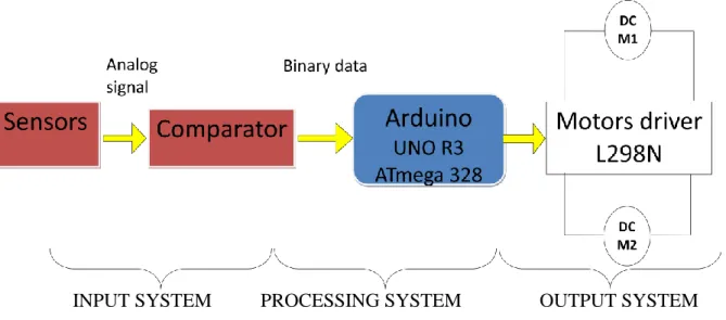
The robot is built with ATmega328; L298N, LDR sensors, LM324, 7805 IC regulator platform consisting of a toy wheel and gear box car and battery. The robot is designed using two motors controlling wheels. It has infrared sensors on the bottom for detect black tracking tape .It captures the line position with the help of these optical sensors called opto-couplers mounted at front end of the robot. (Each opto-coupler consists of an IR LED and an LDR Sensor) when the sensors detect black surface, output of comparator, LM324 is low logic and for white surface the output is high. It reports to the microcontroller for accurate control and steering of motors. Microcontroller ATmega328 and Motor driver L298N were used to drive the motors.
INPUT SYSTEM PROCESSING SYSTEM OUTPUT SYSTEM
Fig 4.1: Block diagram of the autonomous robot
2.3. The input system:
2.3.1. Sensors:
The robot uses LDR sensors to sense the line; an array of three IR LEDs (TX) and sensors (Rx), facing the ground used in this setup.
IR reflective sensors have one emitter (IR LED) and one receiver (LDR).
If we have white surface it reflects the light and it will sensed by the receiver, similarly if we have black surface it absorbs the light and receiver cannot sense light.
The LDR has property that if IR light fall on it its electrical resistance comes down (i.e. it comes down from 150kΩ to 10kΩ if no noise present).For sense the change in resistance we use voltage divider circuit (as shown in figure below). [14]
Say receiver has resistance:
Rs=150kΩ without light (on black surface) Rs=10kΩ with light (on white surface) The voltage that goes to comparator:
Without light: (on black surface)
With light: (on white surface)
Fig 4.2: sensor circuit diagram
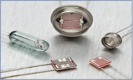
A light dependant resistor also know as a LDR, photo resistor, photoconductor or photocell, is a resistor whose resistance increases or decreases depending on the amount of light intensity. LDRs (Light Dependant Resistors) are a very useful tool in a light/dark circuits. LDRs can have a variety of resistance and functions. For example it can be used to turn on a light when the LDR is in darkness or to turn on a light when the LDR is in light. It can also work the other way around so when the LDR is in light it turns on the circuit and when it‟s in darkness the resistance increase and disrupts the circuit.
Fig 4.3: types of Light dependant resistor
The way an LDR works is that they are made of many semi-conductive materials with high
resistance. The reason they have a high resistance is that are very few electrons that are free and able to move because they are held in a crystal lattice and are unable to move. When light falls on the semi conductive material it absorbs the light photons and the energy is transferred to the electrons, which allow them to break free from the crystal lattice and conduct electricity and lower the resistance of the LDR.[13]
An analog signal is obtained in output, depends on the amount of light reflected back, which is provided to the comparator to produce 0s and 1s which are then fed to the microcontroller.
2.3.2. Comparator:
Comparator is a device, which compares two input voltages and gives output high or low. In circuit diagram it is normally represented by a triangle having-Inverting (negative) Input, Non-Inverting (positive) Input (+), Vcc, Ground, Output.
If V+ > V- then Vo= Vcc (Digital High Output is 1), If V+< V- then Vo= 0 (Digital Low Output
is 0).
Fig 4.5.a: circuit diagram of comparator IC
2.3.2.1. The use of comparator in IR sensor:
Two inputs are required for comparator. One input is from receiver (like photo-diode), other is generated by potentiometer. The second voltage is reference voltage for that sensor.
Fig 4.6: comparator connection with IR sensor
Sample calculation: Let V+ = 3.587V
With light: (on white surface)
V- = 2.500v Thus V+ < V- and Vo = 5v. Thus we got digital HIGH output.
Without light (on black surface ):
V- = 4.6875v thus V+ < V- and Vo = 0v. Thus we got digital low output.
2.4. Processing system:
Processing system acts as the Brain of robot, which generates desired output for Corresponding inputs. For that we use microcontrollers. In present days, there are several companies that manufacture microcontrollers, for example ATMEL, ATmega, Microchip, Intel, Motorola etc. We will be using ATmega328 microcontroller in our robot. It is an ATMEL product.
We can use any microcontroller for that. But we use ATmega8, because it has following extra features:
1. It is an ISP (In System Programmable) device. It means programming of ATmega328 IC
can be done without removing it from the system.
2. It has on chip PWM (Pulse Width Modulation) circuit at three pins (Pin 3, 5, 6, 9, 10, and
11).
3. It has an inbuilt RC oscillator. (Oscillator is a clock generator circuit). 4. It consumes low power than other microcontrollers.
2.5. The output system:
2.5.1. Motor output system:
For moving a robot we have two DC motors attached to wheels gears. DC motors are most easy to control. One DC motor requires only two signals for its operation. If we want to change its direction just reverse its polarity of power supply across it. We can vary the speed by varying the voltage across motor.
The DC motors don‟t have enough torque to drive a robot directly by connecting wheels in it. Thus Gears is used to increase the torque of DC motor on the expense of its speed.
Rotational power is constant for DC motor for a constant input electrical power. Thus the torque is inversely proportional to the speed. Therefore, to increase the value of the torque we have to lose speed.
In our project we have used a gear box extracted from toy cars that contain several combinations of gears.
2.5.2. The motor drive:
From microcontroller we cannot connect a motor directly because microcontrollers cannot give sufficient current to drive the DC motors. Motor driver is a current enhancing device; it can be act as switching device. Thus we insert motor driver in between motor and microcontroller.
Motor driver take the input signals from microcontroller and generate corresponding output for motor.
2.5.3. Background-information to the h-bridge circuits:
An H-bridge is an electronic circuit which allows us to reverse the polarity of a device (such as a DC-motor) by controlling four switches.
These H-bridges will often be found in robotics to control a motor rotation in two opposite directions.
Modern systems use integrated circuits for motor control, but to learn the basic fundamentals and the dimensioning problems of power supplies it might be important to study an archaic circuit for motor controls.
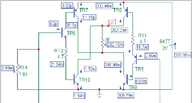
2.5.4. An H-bridge for 3 volt power supplies:
The driver circuit for the Hyper-Peppy robots contains two PNP-Transistors TR7 and TR8, respectively NPN-Transistors TR9 and TR10.
In this design we always allow only two transistors to simultaneously conduct currents into motor M: via TR7 and TR10 or alternatively via TR8 and TR9.
In the driver stage we may identify the DC-motor M. The preamplifier of the driver circuit is being simulated by resistor R14. This resistor will pull the base-ports of transistors TR6 and TR5 to 0V, which results in a condition in which only the right-sided branch is conducting a significant current.
Transistors TR8, TR5 and TR9 are conducting and the other transistors are blocked. As soon as we switch R14 to a positive voltage the right-sided branch will be blocked and the motor current will be reversed.
The 3V-power supply is an ideal condition for a robot with a battery pack of only 2 cells. The PNP-transistors however cannot easily be integrated in an IC such as the L293D. An IC however has other advantages such as reliability, protection against bad circuitry and reduced PCB-area and low weight.
For this reason a L293D-chip with a dual H-bridge circuitry have been used to simultaneously control two DC-motors.
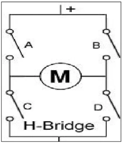
Fig 4.8 an H-bridge schematic
The circuit has four switches A, B, C and D. Turning these switches ON and OFF can drive a motor in different ways.
1. Turning on Switches A and D makes the motor rotate clockwise 2. Turning on Switches B and C makes the motor rotate anti-clockwise 3. Turning on Switches A and B will stop the motor (Brakes)
4. Turning off all the switches gives the motor a free wheel drive
5. Lastly turning on A & C at the same time or B & D at the same time shorts your entire circuit. So, do not attempt this.
![Fig 2.5: Diagrams of brushed and brushless DC motors[10]](https://thumb-eu.123doks.com/thumbv2/123doknet/8177136.274533/22.892.144.767.481.711/fig-diagrams-brushed-brushless-dc-motors.webp)
![Fig 3.1: The board of the ARDUINO UNO R3.[3]](https://thumb-eu.123doks.com/thumbv2/123doknet/8177136.274533/31.892.136.802.145.761/fig-board-arduino-uno-r.webp)