an author's
https://oatao.univ-toulouse.fr/26942
https://doi.org/10.1016/j.ijmecsci.2019.105370
Sánchez Camargo, César Moisés and Hor, Anis and Mabru, Catherine A robust inverse analysis method for
elastoplastic behavior identification using the true geometry modeling of Berkovich indenter. (2020) International
Journal of Mechanical Sciences, 171. 105370. ISSN 0020-7403
A
robust
inverse
analysis
method
for
elastoplastic
behavior
identification
using
the
true
geometry
modeling
of
Berkovich
indenter
Cesar-Moises
Sanchez-Camargo
∗,
Anis
Hor
,
Catherine
Mabru
Institut Clément Ader (ICA), Université de Toulouse, CNRS, ISAE-SUPAERO, UPS, INSA, Mines-Albi, 3 rue Caroline Aigle, 31400 Toulouse, France
Keywords: Nanoindentation Finite element modeling Inverse analysis Friction effect
a
b
s
t
r
a
c
t
Theparametersdescribingtheelastoplasticbehaviorofthe316Lausteniticstainlesssteelareidentifiedthrough inverseanalysisbasedonfiniteelementmodelingoftheBerkovichnanoindentationtest.Thetruegeometryof theBerkovichindenterisintroducedinaxisymmetricand3Dfiniteelementmodelsusingexperimental nanoin-dentationdataobtainedbyadaptingthecalibrationmethodproposedbyOliverandPharr[1].Then,usingthese trueindentershapemodels,theelastoplasticparametersofthe316Lareestimatedwithhighaccuracycompared totheparametersobtainedfromtensiletestidentification.Theindentationcurvewascorrectlydescribedbythe numericalmodelforalltheanalyzedindentationdepths,evenforindentationsinferiorto100nm,whichisa challengeuntiltoday.The3Dindentermodelproducesaresidualimprintveryclosetotheexperimental indenta-tionmark.Thefrictionanalysisbetweentheindenterandthesamplesurfacerevealssmallchangesinthesurface deformation,introducinganincreaseonthehardness,whichdisappearsastheindentationdepthdecreases. Thesestudiesdemonstratethatthemostimportantaspectintheelastoplasticparameteridentificationisthe correctrepresentationoftheindentergeometryinthefiniteelementmodel.
1. Introduction
Indentationisapopularmethodforevaluatingelastic-plastic prop-ertiesofmaterialsandstructures,includingelasticmodulus,hardness andyieldstrength[2,3].Severalresearchstudieshaveusedthistestto analyzework-hardening,residualstress[4],andfracturetoughness[5], etc.,thesepropertiesareimplicitlyrelatedwithindentationresponse. Thislocalizedtestcanalsobeappliedtomeasurethepropertiesof indi-vidualphasesaswellasglobalpropertiesofcompositematerials, coat-ingsandmultilayers[6,7].Sinceitrequiresmuchlesseffortonsample preparationthanothertechniques, itis inparticularusefulforsmall materialstructuresandbiologicalmaterials(includinglivingtissues). Duetotheinvolvedfinitelocaldeformationandnonlinearcontact con-ditions,numericalmodelingofindentationisavaluabletoolto under-standofthelinkbetweenindentationdataandmaterialproperties,and tocorrelatetheindentationresultswithmaterialparameters.Then,an inverseanalysiscanbecarriedouttoidentifythesematerialproperties fromindentationtests.
Theelastoplasticcharacterizationofmetalsbynanoindentationtest remainsoneofthebiggestchallengesinthemicro-characterization do-main[8,9,10].Themethodsofelastoplasticcharacterizationby nanoin-dentationtestcanprovideaccesstothemechanicalbehavior[11]at multiplescalesandinconditionswheretheconventional methodsof mechanicalcharacterization(e.g.tensiletest)aredifficultor
impossi-∗ Correspondingauthor.
E-mailaddress:[email protected](C.-M.Sanchez-Camargo).
bletoapply,e.g.multi-layerssystems,functionalizedsurfacesamong others.Theadvantageoftheuseofthenanoindentationtechniqueis thatitisabletomechanicallytestvolumesofmatterinthemicroscale, producingexperimentaldataofhighaccuracy.
Thenanoindentationtestproducestwomainpiecesofinformation: theresidualimprintandtheloading-unloadingcurve(referredalsoas nanoindentationcurve).Theparametersdescribingtheresidualimprint andthenanoindentationcurveare:hmisthemaximumdisplacementof theindentermeasuredfromthefreesurface,hcisthedepthtothe
con-tactpoint;hsisthedistancefromthecontactpointtothefreesurface,
A(z)isthecrosssectionareaoftheindenteratthecontactpoint,Pmis
thepeakindentationload,Sistheslopeoftheunloadingbranchofthe nanoindentationcurve,andhfisthelastpointofcontactbetweenthe
indenterandthetestedsurface.
Actually,severalmethodsofestimationoftheelasticmodulusand thehardnessofthetestedsurfaceareavailable[12,13].Thesemethods purelyelasticarebasedonlyontheunloadingstageofthe nanoinden-tationtest(Fig.1)[14].Inthecaseoftheelastoplasticcharacterization, twomaintypesofapproacheshavebeendevelopedsincetheapparition of thenanoindentationtest:theanalyticalinversemethods[9,10,11]
andthenumericalinverseanalysis[8,15].
Ingeneralterms,theanalyticalmethodsarebasedonthe hypoth-esisofarepresentativestrainassociatedwiththegeometryofthe in-denter[16],i.e.thestraininducedinthesurfaceisindependentofthe
Fig.1. (a)Schemaoftheindentation,and(b)typical corre-spondingnanoindentationcurve.
Fig.2. AtomicForceMicroscopy(AFM)capturesofBerkovich indenters:(a)wornindenterwithtipradiusof1200nmand (b)newindenterwithtipradiusof500nm.
indentationdepth.Usingadimensionalanalysis[17],andfiniteelement modeling,a vastamount of workshas beenpublished, forinstance, amongthemostrelevant,thosepresentedin[18,19,20,21,22,47–50]. Suchmethodsarebasedonfiniteelementsimulationsofawiderange ofelastoplasticparameterstodeterminethecoefficientsofthe dimen-sionlessfunctions.These methodsweredevelopedusingthe microin-dentationonarangeof1<hm≤20𝜇m,where,accordingtothe
au-thors,thedefectsanddeviationsontheindentercanbeneglected.In thenanoindentationscale,i.e.0<hm≤200nm[23,24],thewearand thedeviationsontheindentertiparenotnegligible.Theeffectsofthese deviationsonindentershapeareconfirmedbyDaoetal.[19],where theyobservedinfiniteelementsimulationsthatavariationof2° onthe halfangleofaconicalindenterresultsin15−20%variationsinthe
P−hloadingcurvature.
Since, in nanoindentation,the effectsof thewearand deviations onthetipmustbetakenintoaccountonfiniteelementsimulationsa methodtoreproducethephysicalindentergeometryinthefinite ele-mentmodelisrequired.Ingeneraltwoapproachesrelatedtothis is-suecanbefoundintheliterature:i)themodelingoftheindenterasa sphero-conicalrevolutionshape[25,26,27,28,29]andii)themodeling oftheindenterfromacloudofpointsgathered withanatomicforce microscope[30,31].Aremarkableexampleofthefirstapproachwas proposedbyPelletieretal.[25].Theprincipleofthismethodconsists inthedescriptionoftheBerkovichindenterbasedontheuseofthe func-tionareaproposedbyOliveretal.[1],whichrelatesthecrosssection areaof theindenter tothedistancemeasuredfromitstip.Fromthis functionareaanequivalentfunctionareadescribingasphero-conical indenterisderived.Thelimitationofthisapproachisthattheindenter issphero-conical; thereforetheresidualimprintcannotbe compared withtheexperimentalresidualimprintofaBerkovichindenter.
Themostrelevantworkfoundforthesecondapproachwasproposed byKrieretal.[30].TheauthorscapturedtheBerkovichindenter ge-ometrywithanAtomicForceMicroscopy(AFM) andthenintroduce thetruegeometryin thefiniteelementmodel. Theirmethodis able toreproducequitewell indentationsdowntohm =40nm.However theimplementationofthemethodisachallengeforseveralreasons,in particularthecorrectionoftheAFMcloudofpoints.Inthisworkthe
authorsstatedthatthebluntingtipdefectaffectstheload-displacement curve,especiallytheloadingphase,andalsotheelastic–plasticstress andstrainfieldsbeneaththeindenter.Theyhighlightedthatthiseffect ontheelastic–plasticstrainfieldisarealandphysicaleffectthat can-notbeavoidedandlimitedbyananalyticalmodel[30].Thisstatement isverifiedthroughAFMcapturesofthetwoBerkovichindenters avail-ableforthepresentresearch(Fig.2),whichexhibitdeviationsonthe selectedoperativerange.Butalsotheartefactsthatmustbecorrected ifthecaptureisusedtoreproducetheindentergeometryinthefinite elementmodelarevisible.
Althoughthestudiescitedaboveaddresstheproblematicassociated withthedescriptionofthephysicalBerkovichindenter,itdoesnotexist, accordingtoourpresentknowledge,areliableandeffectivemethod tointroducethetrueindentergeometryon thefiniteelement model allowingthecorrectrepresentationofindentationsonstrainhardening solidsintheinterval0<hm≤500nm.Theobjectiveofthispaperisto
providesuchmethodandevaluatethefollowingaspects:
1 Theabilityoftheproposedmethodtocorrectlydescribetheshapeof theBerkovichindenterinbothaxisymmetricand3Dfiniteelement models.
2 Theaccuracyoftheelastoplasticparametersidentificationusingthe inverseanalysisbasedonthefiniteelementmodelincludingthetrue indentergeometry.
3 Numericaleffectsofthefrictionanditsroleinthenanoindentation simulation.
2. Experimentalstudy
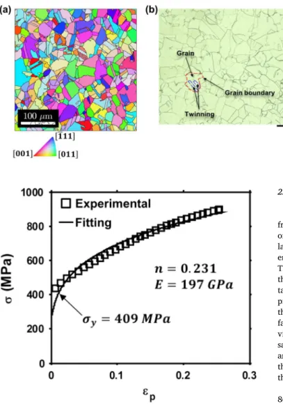
Thematerialusedinthisresearchisthesingle-phaseaustenitic stain-lesssteelAISI316L[32].Themicrostructureiscomposedofequiaxed grainswithamultitudeoftwinning(Fig.3a).Thegrainsizeisbetween 10and40𝜇m.Thecrystallographicstructureofthisausteniticphaseis Face-CenteredCubic(FCC).Theelectronbackscatterdiffraction(EBSD) mapshowninFig.3bhighlightsanon-texturedmaterial.
Themechanicalbehaviorofthe316Lwascharacterizedbyuniaxial tensiletest[33].TheYoung’smodulusobtainedwiththistensiletestis
Fig.3. (a)Microstructureand(b)textureof316Lstainless steel.
Fig.4. Truestress-truestraincurveof316Lstainlesssteel.
method(Fig.4),accordingtotheconstitutiveequation[19]:
𝝈 =𝝈𝒚 ( 1+ 𝑬 𝝈𝒚𝜺𝒑 )𝒏 (1)
where𝝈yrepresentstheyieldstressandnthehardeningexponent.The
valuesofyieldstressandhardeningexponentidentifiedfromthe ten-siletest,usinganoffsetof0.2%plasticstrain,wereconsideredasthe referencevaluesoftheelastoplasticparametersandwereusedasa com-parisoninthefollowingtoassesstheaccuracyoftheanalysisproposed inthispaper:𝝈y=409MPaandn=0.231
2.1. Surfaceoptimizationfornanoindentationexperiments
Ananoindentationspecimenwasmachinedinacubeof2cmside fromthe316Lsameroundbarstockthatwasusedfortensiletest.In order toensureasurfacerepresentativeofthebulkmaterial, thetop layerofthemachinedsurfacewasremovedgraduallyfollowingthis it-erativeprocedure:firstly,theinitialheightofthesamplewasmeasured. Then,mechanicalgrindingusingSiCpaperswasdownto1200gritand thefinalheighthasbeenre-determinedagain.Then,five nanoinden-tationsusingPm =50mNwereconducted.Finally,theheightof the pile-upfromAFMcapturesoftheresidualimprintwasestimated.Once thepropertiesmeasured(i.e.hmandpile-up)becameconsistent,the
sur-facewaspolishedusingadiamondsolutionof1𝜇m,andfinishedwith vibratorypolishingusingcolloidalsilicaduringeighthourswithonly sampleweight[34].Thevariationsinthemeasuresofhm (Fig.5(a))
andtheheightofthepile-up(Fig.5(b))duringtheprocedurerevealed thatthemachiningprocessinducedagradientofproperties,extending througha250𝜇mlayerfromthefreesurfaceofthesample.
Themeanvalueofhmwas 820nmonthestabilized surface,and
860nmonthepolishedsurface(Fig.6(a)).Theresidualimprintonthe polished surfacerevealedthe influenceof the crystallographic char-acteristics of theindented point in theform of asymmetric pile-ups (Fig.6(b)).
The prepared surface was inspected by X-ray diffraction using sin2𝜓 method to analyze the residual stress state [35], finding 𝜎11 = 12∓8MPa and 𝜎22 = −15∓11MPa. The surface can thus be considered as free from internal stresses. The microstructural-crystallographiccharacteristicsweredeterminedthroughEBSD analy-sis.ThetreatmentoftheEBSDdata[36]revealedadistortionless mi-crostructurefreeofpre-hardening,withanintragranularmisorientation rangingfrom0° to4° atthecenterofthegrains(Fig.7(a)).Theroughness oftheworkingsurfacewasestimatedfromAFMcaptures(Fig.7(b));it wasgloballyRa=4nmandlocallyRa=1.4nm.ThelocalvalueofRa wasusedtodefinetheminimumvalidvalueofhmonthissurface,which
Fig.5. Surfaceoptimizationprocedure:(a)evolutionofhm
and(b)evolutionoftheheightofthepile-upasafunctionof theremovedlayer(affectedbymachining).
Fig.6. Effectsofpolishing:(a)evolutionofhmand(b)residual
imprintofthepolishedsurface.
Fig.7. Surface stateof the polishedsurface:(a) crystallo-graphicmisorientationstateand(b)roughnessstate.
Table1
Finalsurfaceproperties.
Roughness
Crystallographic misorientation
(pre-hardening) Residual stresses R a = 4 nm less than 5° 𝜎11 ≈ 0 MPa/ 𝜎22 ≈ 0 MPa
isofabout28nm,i.e.20timesRa[24].Thepropertiesofthesurfaceat
theendofthepreparationprocedurearelistedinTable1.
2.2. Nanoindentationexperiments
Oncetheworkingsurfacewasprepared,thenanoindentation exper-imentswereoptimizedandconductedonthepolishedsurface.Allthe nanoindentationexperimentswereconductedusingthewornBerkovich indenteroftipradiusr=1200nm(Fig.2(a))inloadcontrolledmode atroomtemperatureonaNHT2commercialnanoindenterfromAnton Paarinstruments.Theoptimumloading/unloadingratewasdetermined experimentally on the optimized working surface. Series of nanoin-dentationexperimentswereconductedusingaconstantloadingforce
Pm=10mNandvaryingtheloadingrate.Thetotalindentationwork
(Wt,Eq.(11))constantuntilavalueofloadingratenearto25mN/min,
afterthisvalue,Wtincreaselinearly(Fig.8(a)).Thereforewe consid-eredthatusingloadingrateslowerthan25mN/minallowsneglecting thetimedependenteffects(e.g.indentationcreep)forPm=10mN.
Onthesmallerscale,thetimedependenteffectscanbeobservedin thefirststageoftheloadingnanoindentationcurve(Pmbetween0and
0.5mN),whereloadingratesgreaterthan6mN/minintroduceaslight increaseintheloadingcurve(Fig.8(b)).Finallyusingtheloadingrate closeto6mN/minallowsobtainingcomparableindentationcurvesfor differentindentationloadingvalues.Thevaluesofloading/unloading rateusedinthisstudy(Table2)wereselectedrespectingthisrule,and consideringtheacquisitionfrequencytohavesimilarquantity experi-mentalpoints(i.e.usinglowerloadingratesforthesmallerPm).
Basedon thisinformation,theexperimentalprotocolwasdefined (Table2).ThistablealsopresentsthehmproducedbytheselectedPm.
Table2
Experimentalprotocolforindentationtestsusingthe wornBerkovichindenter.
P m ( mN ) h m ( nm ) Loading / unloading rate ( mN / min )
0.3 25 0.5
1 68 1
3 150 3
10 330 6
15 420 6
Themaximumhmisinferiorto500nm,asrequiredforthepresentstudy,
andtheminimumhmisgreaterthan20nm,whichisvalidwithrespect
tothelocalroughnessoftheworkingsurface(Fig.7(b)).
Atotalofninenanoindentationswereappliedforeachofthefive peakloadslistedintheTable2,spacedenoughtoavoidinterferences. Accordingtotheliterature[24],theindentationmustbespacedatleast threetimesthediameteroftheimprintmark.Inthisstudyweuseda spacingoftentimesthediameteroftheresidualimprint.Fromeach groupofnineindentationstheP−hcurvessharingthesameloading pathwereselected(Fig.9(a)),andanAFMcaptureoftheirrespective residualimprintswastaken(Fig.9(b)).
3. Numericalmethod
3.1. Finiteelementmodelingofthespecimen
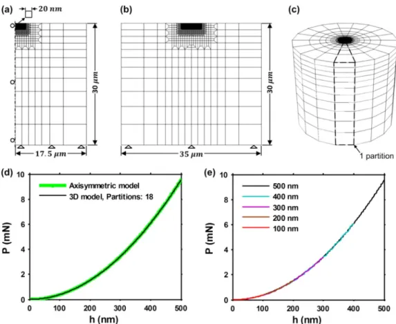
Allthesimulationsinthispaperwereconductedincontrolled dis-placementappliedtotheindenter.Thespecimenwasmodeled asan axisymmetricbodyandasafull3Dmodel[37]usingtheimplicit non-lineargeometryFEalgorithminAbaqus[38].
Firstly,theaxisymmetricmodelwasoptimizedthroughamesh re-finement convergence analysis, using a fixed hm = 500nm, a rigid
cone equivalent to a perfect Berkovich indenter [39], a frictionless contact,andtheelastoplasticparametersoftheEq.(1):E=180GPa,
𝜎y =148MPa, n=0.278[40].Theiterativeprocedurewasapplied
Fig.8. Analysisofnanoindentationtimedependenteffectson 316L:(a)effectsofloadingrateonWtand(b)effectsofloading
rateonthefirstportionoftheloadingnanoindentationcurve.
Fig. 9. Nanoindentation experiments using the worn Berkovichindenter:(a)P−hcurvesand(b)residualimprints associatedtoeachP−hcurve.
Oncetheoptimummeshandsizeofthespecimenwasfoundforthe axisymmetricmodel(Fig.10(a)),thecharacteristicsoftheaxisymmetric modelwerereplicatedonthe3Dmodel(Fig.10(b)).Then,themesh densityofthe3Dmodelwasincreasedbyaddingpartitions(Fig.10(c)), untiltheloadingcurvesofthe3Dandtheaxisymmetricmodelswere equivalents(Fig.10(d)).
Finallybothmodelswereparametrized,usingasmasterparameter
hm:thereforethesamemodelwassuitablefor theanalysisofalarge rangeofhm,ensuringsimilarcontactconditions(Fig.10(e)).
3.2. Finiteelementmodelingoftheindenter
Theproposed methodis basedontheuseofseveralvaluesofthe sectionareaAoftheindenterandtheircorrespondingvaluesofz,i.e.
A(z),withztheneutralaxisoftheindenter(Fig.11).ThevaluesofAare usedtodefinethepointsofthegeneratrixatthecorrespondingzvalues. Then,thegeneratrixisrotatedaroundthezaxisfollowingacircular directrixtoobtainaconicalindenter(Fig.11(a)).Inthecaseofa3D indenter,thegeneratrixismovedalongastraightdirectrixtogenerate onewalloftheindenter.Then,usingacircularpatterntheotherthree wallsaregeneratedandtrimmedontheintersections(Fig.11(b)).The stepsrequiredtoobtainthegeneratrixforbothindentersareexplained below.
Forsimplicity,theexplanationofthemethodisbasedonthe assump-tionofaperfectBerkovichindenter(Fig.11).Consideringtheareaofthe circularsectionofacone,theassociatedradiusisgivenbytheequation:
𝐫(𝐳)= √
𝐀(𝐳)
𝝅 (2)
wherer(z)isthegeneratrixintheaxisymmetricfiniteelementmodel (Fig.11(a)).
Movingtothe3Dindenter,thesectionoftheindenterhasashape ofanequilateraltriangle(Fig.11(b)).Thelengthof eachsideofthe
triangleisgivenbytheequation:
𝑎(𝑧)= √
𝐴(𝑧)√4 3
(3)
Then,theperpendiculardistancefromtheaxisoftheindentertothe sideofthetriangleiscomputedfrom:
𝑐(𝑧)= 𝑎(𝑧) 2 tan
(
30◦) (4)
Inthiscasec(z)isthegeneratrixofthewall,anda(z)isthe direc-trix.Introducingtheindenteronthefiniteelementmodelrequiresthe valuesofAalongtheaxiszoftheindenter.Awell-knownrelationisthe BerkovichfunctionareaA(z)=24.5z2[1].Usingthisrelationonthe
proposedprocedureaperfectBerkovichindenterisgenerated,whichis characterizedbyanangle𝜃 =70.3° inthecaseofanaxisymmetric in-denter(Fig.11(a)),orbyanangle𝛼 =65.3° inthecaseofa3Dindenter (Fig.11(b)).
Sincetheobjectiveis tointroducethetrue indentergeometryon thefiniteelementmodel,itisrequiredtoestimateAatseveralpoints ofthezaxisofthephysicalindenter.Thisproblemwassolvedafew decadesagobyOliverandPharr[1].Theprincipleofthismethodisto estimateAatagivencontactdepth,hc,throughtheindentationona
well-knownmaterial(Fig.1).Ontheirworktheyproposedtousethe fusedquartzasindentedmaterialwiththeelasticconstantsEs=72GPa
and𝜈s=0.17;andadiamondBerkovichindenterwiththeelastic
con-stantsEi=1141GPaand𝜈i=0.07.
Firstly,Aiscalculatedusingtherelation:
𝑆= 𝑑𝑃 𝑑ℎ = 2 √ 𝜋𝐸𝑟 √ 𝐴 (5)
whereSisthecontactstiffness,computedattheinitialportionofthe unloadingdata(Fig.1),andthereducedmodulus,Er,iscomputedusing
Fig.10. Nanoindentationfiniteelementmodeling:(a)axisymmetricmodel(b)sectionofthe3Dmodel(c)partitioningofthe3Dmodel,(d)equivalencebetween the3Dandtheaxisymmetricmodeland(e)loadingcurvesproducedbytheparametrizedmodelsonawiderangeofhm.
Table3
Experimentalprotocolforindentationsonfusedquartz.
Indentation numbers Peak load (mN)
Loading/unloading rate (mN/min) Oliver and Pharr [1] 1–10 0.1 0.6 11–20 0.3 1.8 21–30 1 6 31–40 3 18 41–50 10 60 51–60 20 120 Extension 61–70 40 240 71–80 60 360 81–90 80 480 therelation: 1 𝐸𝑟 =1−𝜈𝑠 2 𝐸𝑠 +1−𝜈𝑖 2 𝐸𝑖 (6) where𝜈sandEsaretheelasticconstantsforthespecimen,and𝜈iandEi
arethesameparametersfortheindenter. Then,hciscomputedfromtheequation:
ℎ𝑐=ℎ𝑚−ℎ𝑠 (7)
wherehsisthedeflectionofthesurfaceoutsidethecontactarea(Fig.1),
whichiscomputedfromtheequation:
ℎ𝑠=𝜋2(𝜋 −2)𝑃𝑆𝑚 (8)
Onthisstudy,themethodofOliverandPharr[1]wasusedunder threeconsiderations:1)hcis equivalenttoz,2) theoriginal
nanoin-dentationprotocolusedonthefusedquartz(Table3),wasextendedto estimatethevalueofAforacorrespondingvalueofz=500nm,and
3)theelasticconstantsoftheBerkovichindenterandthefusedquartz werethesamethatthoseproposedbyOliverandPharr[1];both,the di-amondBerkovichindenterandthestandardizedsampleoffusedquartz wereobtainedfromthemanufactureroftheNHT2nanoindenter.The indentersgeneratedwiththeproposedprocedurearereferredastrue indenters.
Finally,9valuesofA(z)werecomputedusingtheextendedmethod ofOliverandPhar[1]indentingonfusedquartz(Fig.12),tocovera maximumz=500nm.
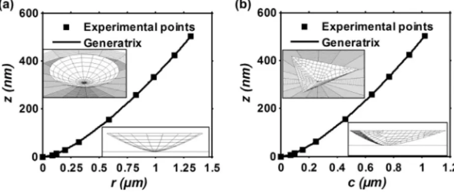
ThephysicalBerkovichindenterwasintroducedinthefiniteelement modelapplyingthisprocedurethroughPythonscriptsinAbaqus,in sep-aratemodelsintheformofaxisymmetric(Fig.13(a))and3D(Fig.13(b)) indenters,respectively.TheexperimentalpointsA(z)weredirectlyused togeneratetheindentergeometriesaddinganinitialpointintheorigin. Nofittingprocedurewasincludedtocreatethegeneratrixofthe inden-ters.Theaxisymmetricmodel(Fig.13(a)),ispresentedintheformof aconeusingthevisualizationcapabilitiesofAbaqus.The3Dindenter (Fig.13(b)),isafull3DrepresentationofthephysicalBerkovichused intheexperiments.
Oncethecharacteristicsofthespecimenandtheprocedureto gen-eratetheindenterwereestablished,thenextstepistodefinethe inter-actionbehaviorbetweenthesurfacesoftheindenterandthespecimen.
3.3. Indenter-specimencontactmodeling
Theinteractionbetweentheindenterandthespecimenwasdefined inAbaqusStandardusingthemaster-slaveconfiguration[38].The mas-tersurfacewastheexternalsurfaceoftheindenter,andtheslavesurface wastheexternaltopsurfaceofthespecimen.Theinteractionbetween theindenterandthespecimenwasanalyzedintwoways:1)in friction-lesscontact,and2)withfrictioncontact.Thefrictionwasintroduced in the modelusing the formulationof Coulombincludedin Abaqus
Fig.11. Geometricspecificationsoftheindenters:(a)conical indenterand(b)3Dindenter.
Fig.12. Experimentalpointsobtainedfromindentationonfusedquartzusing thewornBerkovichindenter.
[38]. Thisformulationassumesthatthere isnorelativemovementif theequivalentfrictionalstressgivenby
𝜏𝑒𝑞= √ 𝜏2 1+𝜏 2 2 (9)
isinferiortothecriticalstress,𝜏crit,whichisproportionaltothecontact
pressure,p,intheform:
𝜏𝑐𝑟𝑖𝑡=𝜇𝑝 (10)
Thefrictioncoefficient,𝜇,isafunctionofthecontactpressure,p, thesliprate,theaveragetemperature,andtheaveragefieldvariables atthecontactpoint.If𝜏crit=𝜏eq,slipoccurs.Inthisstudythefrictionis
consideredisotropic.Thedirectionoftheslipandthefrictionalstressis coincident.
3.4. Optimizationprocedureforelastoplasticparametersidentification
TheLevenberg-Marquardt[41]optimizationalgorithmwasusedto determinetheelastoplasticbehaviorparameters.Theobjectivefunction proposedisformulatedusingbothloadingandunloadingbranchesof theP−hcurve(Fig.1).
Fromtheloadingcurvethetotalindentationwork,Wt,isobtained
withtheexpression:
𝑊𝑡= ℎ𝑚
∫
0 𝑃𝑑ℎ
(11) whichisusedtodefinethefirstcomponentoftheobjectivefunctionin theform:
𝑓𝑡=𝑊𝑡𝑛
−𝑊𝑡𝑒
𝑊𝑡𝑒 (12)
whereWtn isthetotalindentationworkobtainedfromthesimulated
loadingcurve,andWteisthetotalindentationworkobtainedfromthe experimentalloadingcurve.
Usingtheunloadingcurve,theelasticindentationwork,We,is
ob-tainedthrough: 𝑊𝑒= ℎ𝑚 ∫ ℎ𝑓𝑃𝑑ℎ (13)
whichisusedtodefinethesecondcomponentoftheobjectivefunction intheform:
𝑓𝑒=𝑊𝑒𝑛
−𝑊𝑒𝑒
𝑊𝑒𝑒 (14)
whereWenistheelasticindentationworkobtainedfromthesimulated
unloadingcurve,andWeeistheelasticindentationworkobtainedfrom theexperimentalunloadingcurve.
UsingtheEqs.(12)and(14),theobjectivefunctionforthewhole
P−hcurveisassembledintheform:
𝑓(𝛽) 𝑚𝑖𝑛= [ 𝑓𝑡 𝑓𝑒 ] (15) where𝛽 representsthesetofelastoplasticparameters.Finally,the mini-mizationoftheobjectivefunctionisachievedusingthealgorithmshown intheFig.14.
Thealgorithmusedinthisworkwassetwithasteptoleranceand functiontoleranceof10−14.Changesinresidualswassetwithavalue
of10−6,andthenumberofiterationswassetasinfinite.
Fig.13. Berkovichindentermodeling:(a)generatrixofthe axisymmetricindenterand(b)generatrixofthe3Dindenter.
Fig.14. Optimizationalgorithmusedfortheelastoplasticparameter estima-tion.
4. Resultsanddiscussion
4.1. Thetrueindentergeometrymodelling
Fortheinvestigatedindenter height,i.e. 0nm<z ≤500nm,the profileofthetrueaxisymmetricindenter(Fig.15(a)),looksmorelike aparabola thana sphero-conicalindenterasstatedbysomeauthors
[25,26,27,28,29].Infact,theprofileofthetrueindenterneverexhibits aparallelismwithrespect totheperfectindenter(70.3°).Thisfound helpstoexplainwhythepolynomialformofthefunctionareausedby OliverandPharr[1]isabletodescribetheBerkovichindenterwithhigh precisionregardlessaphysicalmeaning.Anothermethodtodetermine thefunctionarea,includingaphysicalmeaning,wasproposedby Lou-betetal.[42].Thismethodreliesontheestimationoftheheightofa roundedportion(thetipdefect),connectedtoaperfectindenter.The3D indentermodeledwiththemethodproposedinthispapercannotbe
de-scribedusingthisassumption,becausethesectionsofthetrueindenter arecurved(Fig.15(b)).
Inaddition,thecloudofpointsgatheredbytheAtomicForce Mi-croscopy(AFM) wasdirectly used forcomparisons, founding thatat leastoneofthethreesectionsobtainedfromtheAFMcaptureofthe Berkovichtipispartiallysimilartothesectionofthetrueindenter, ex-hibitingarelationwiththephysicalindenter.
4.2. Elastoplasticparametersidentification
Thethreeelastoplasticparametersofthe316Lconstitutivemodel described in Eq. (1) were estimated from each experimental P − h
curveobtainedwiththeindentationsusingthewornBerkovich inden-ter(Fig.9(a))andtheparameteridentificationroutine(Fig.14).Both perfectandtrueindentermodelswereusedintheaxisymmetricmodels, assumingfrictionlesscontact(𝜇 =0inEq.(10)).Theestimated param-eterswereplottedasafunctionofthemaximumindentationdepthin
Fig.16,andthevaluesoftheparametersobtainedbytensiletestwere includedasreference.
Thethreeelastoplasticparametersobtainedwiththeperfect inden-termodelincreasewithrespecttothereference(tensile)valuewhen
hmdecreases.Fortheminimumvalueofhm,theerrorinthehardening
exponentreaches%err=166i.e.n=0.61,whichisoutoftherangefor
metals[19];theerrorintheyieldstressreaches%err=370andisalso
outoftheparametricrangeofmetals[19].
However,theelasticmodulusandthehardeningexponentestimated withthetrueindentermodelexhibitaconstanttrendnearthe refer-ence. Thehardeningexponentandtheelasticmodulus havea mean error%err=3.7and%err=17.8respectivelycomparedtothereference.
Theerrorintheyieldstressonthemaximumvalueofhmis%err=21.6.
This errorincreaseswiththedecreaseof hmtoreach%err=72.9.In theliterature,theincrease oftheyieldstrengthwiththedecreaseof
hm,reflectedonthehardness,isreferredasindentationsizeeffect(ISE)
[43,44,45].WesupposethattheISEisalreadypresentinthemaximum
hminvestigated,andthatiswhythevalueoftheelasticlimitisgreater
thanthevaluefoundbytensiletest.Thisfindingopenthepossibilities tonewexperimental-numericalstudiesoftheISE,besidestheexisting formulationsbasedonthehardnesse.g.themethodofGaoetal.[44].
Inaddition,theparameter identificationconductedwiththe per-fectindentermodelwasclosetotheknown(reference)solutionforthe indentationcorrespondingtothegreaterhm.Thiseffectcanbeeasily observedintheP−hcurves,wherethesimulationoftheshallow in-dentationexhibitsagreatdifferencewithrespecttotheexperimental curve(Fig.17(a)),whileinthedeepestindentationthedifference be-tweenthemisreduced(Fig.17(b)). Nevertheless,theparameter esti-mationperformedusingthetrueindentergeometryshowedpowerful
Fig.16. Elastoplasticparametersevolutioninfunctionofhm.
Fig.17. Comparisonbetweenthetrueindenterandthe per-fectindenterP−hcurvesin(a)shallowand(b)deep inden-tations.
Fig.18. Comparisonbetweentheexperimentalresidualimprintprofileandthe numericalresidualimprintprofileobtainedwiththe3Dmodel.
capabilitiesofthismodeltofaithfullyreproducetheexperimentalcurve fordeepandshallowindentations(Fig.17(a)and(b)).
Finally,thesectionoftheresidualimprintproducedbythe3Dtrue indentermodelwithPm=15mN,fortherespectivedetermined
elasto-plasticparameters, isvery closeatleast tooneof thethreesections obtainedexperimentally(Fig.18).Thisgreatresemblancealsoconfirms thattheoptimizationroutineconvergedtothecorrectsolutioninthis case.
4.3. Frictionanalysis
Theparameteridentificationroutinewasexecutedtwotimes sepa-ratelyusingthefrictioncoefficients𝜇 =0.1and𝜇 =0.2respectively, foreachinvestigatedexperimentalindentationonthe316L.The start-ingpointoftheroutinewasthelastsetofparametersdeterminedwith
thefrictionlessconfiguration of eachparameter identification execu-tion.Thetrueindenterfiniteelementmodelwasused.Inallcases,after afewiterationstheroutinestoppedbecausethechangesinthecurve werenegligible(Fig.19(a)and(b)),inconsequencethechangesinthe valueoftheparameterswerealsonegligible.Therefore,theeffectofthe investigatedfrictioncoefficients(𝜇 =0; 𝜇 =0.1; 𝜇 =0.2)were evalu-atedusingthedeterminedelastoplasticparametersfortheexperimental
Pm=15mN.Theresidualimprintshowedadecreaseoftheheightofthe pile-up(until31nmfor𝜇 =0.2),comparedtothefrictionlesscontact (Fig.19(c)),revealingsmallvariationsinthecontactarea.
Basedonthisevidence,thehardness,H=Pm/A(hc)[1],was com-putedfortheexperimentalP−hcurveswithPm=3mN, Pm=10mN
andPm=15mNusingtheAFMcapturesoftheircorresponding
resid-ualimprints.Inthecaseofthenumericalmodels,A(hc)wasdetermined athm.Theresultswereplottedinfunctionofhm(Fig.20).Theresults
showanincreaseofHwiththedecreaseofhm.Fortheindentations
in-feriortohm=200nm,theeffectsofthefrictionarereduced,i.e.the
changesinthecontactareaarenegligible.Forindentationssuperiorto
hm=200nm,theexperimentalHisclosetothesimulationusing
fric-tionlesscontact,andtheincreasewhen𝜇 = 0.2induces%err=19.6,
meaningadifferenceofHabout490MPa.
Theliteraturereportsamaximumincreaseof ~ 20%inthe hard-nessforcontactswithfrictioncoefficients𝜇 >0[46].Themaximum differencefoundinthiswork(%err=19.6)isconsistentwiththese ob-servations.However,forthedeeperindentationsanalyzedinthiswork, thevaluesofthehardnessobtainedusingfrictionlesscontactarecloser totheexperimentalvalues.
Mataetal.[46]observedtwoeffectsofthefrictiononthepile-up: 1)theheightofthepile-updecreaseswiththeincreaseofthefriction coefficient,and2)theindentationswithlowheightofpile-upareless sensitivetothevariationsofthefrictioncoefficient.Thetwoeffects ob-servedbyMataetal.arepresentedinthisstudy(Fig.21).Thefirstone isobservedwithindentationsofhm>300nm,whereamaximum
dif-ferenceof27.8nmontheheightofthepile-upisobservedcomparing frictionlesscontactandcontactwithfrictioncoefficient𝜇 =0.2.The secondeffectisobservedwithindentationsofhm<100nm,wherethe
Fig.19. Frictioneffects:(a)inshallowand(b)indeepindentation,ontheP−hcurves,(c)ontheresidualimprint.
Fig.20. Frictioncoefficienteffectonthesurfacehardness.
Fig.21. Effectsofthevariationsofthefrictioncoefficientonthepile-upheight.
5. Conclusion
Anewmethodologytoimprovetherepresentationofthegeometryof thephysicalBerkovichindenterinthefiniteelementmodelisproposed inthispaper.
Thisinclusionofthephysicalindenterinthefiniteelementmodel leadstoacorrectreproduction oftheexperimentalP− hcurveand
residualimprintofthetestedmaterial,providinganestimationofthe elastoplasticparameterswithsignificantlyimprovedaccuracyinthe op-erative range0<hm≤500nm. Theobservedvariationsoftheyield
stressasafunctionoftheindentationdepthopennewinsightsonthe indentationsizeeffect,which nowcanbe analyzedthrough sophisti-catednumericalmodelsonindentationswithhm<100nm.Thispaper
focusedontheanalysisofstrainhardeningsolids,howevercomplex mi-cromechanicalsystems(e.g.ultrathinlayers,nanocrystallinestructures, etc.) canbe analyzedusingtheaccuratefiniteelementmodelof the indentergeometry.
Theeffectsofthefrictioncoefficientwereobservedinthecontact interface betweentheindenter andthesamplesurfacemodifyingthe valueofthehardness,whichis ingoodagreementwithotherworks reportedintheliterature.Noeffectsofthefrictioncoefficientusedin thefiniteelementsimulationswereobservedontheP−hcurveoron theestimatedparameters.
DeclarationofCompetingInterest
None.
Acknowledgments
This workwaspartiallysupportedbytheMexicanCouncilof Sci-enceandTechnology(CONACYT).TheassistanceofDr.VictorSanchez inthereviewofthismanuscriptisgratefullyacknowledged.Wewishto acknowledgetheassistanceofMr.ThierryMartinfortheoptimum per-formanceofthenanoindenter,andthesupportofalltheISAE-SUPAERO DMSMteam.
References
[1] Oliver WC , Pharr GM . An improved technique for determining hardness and elastic modulus using load and displacement sensing indentation experiments. J Mater Res 1992;7:1564–83 .
[2] Iracheta O , Bennett C , Sun W . Characterization of material property variation across an inertia friction welded CrMoV steel component using the inverse analysis of nanoindentation data. Int J Mech Sci 2016;107:253–63 .
[3] Ben Ismail A , Rachik M , Mazeran P-E , Fafard M , Hug E . Material characterization of blanked parts in the vicinity of the cut edge using nanoindentation technique and inverse analysis. Int J Mech Sci 2009;51:899–906 .
[4] Zhu L , Xu B , Wang H , Wang C . Measurement of residual stress in quenched 1045 steel by the nanoindentation method. Mater Charact 2010;61(12):1359–62 .
[5] Romana L , Thomas P , Bilas P , Mansot JL , Aldana Aranda D . Use of nanoindentation technique for a better understanding of the fracture toughness of Strombus gigas conch shell. Mater Charact 2013;76:55–68 .
[6] Lai D , Xu J , Xie Z , Habibi D , Munroe P . Mechanical characterization of a novel nanocrystalline coating: first-principles calculations and nanoindentation. Mater Charact 2012;68:1–6 .
[7] Bouzakis K-D , Michailidis N , Hadjiyiannis S , Skordaris G , Erkens G . The effect of specimen roughness and indenter tip geometry on the determination accu- racy of thin hard coatings stress–strain laws by nanoindentation. Mater Charact 2002;49(2):149–56 .
[8] Kang J , Becker A , Sun W . Determining elastic–plastic properties from indentation data obtained from finite element simulations and experimental results. Int J Mech Sci 2012;62:34–46 .
[9] Kim M , Pandian Marimuthu K , Lee JH , Lee H . Spherical indentation method to eval- uate material properties of high-strength materials. Int J Mech Sci 2016;106:117–27 .
[10] Nguyen N-V , Kim JJ , Kim S-E . Methodology to extract constitutive equation at a strain rate level from indentation curves. Int J Mech Sci 2019;152:363–77 .
[11] Pham T-H , Kim JJ , Kim S-E . Estimating constitutive equation of structural steel using indentation. Int J Mech Sci 2015;90:151–61 .
[12] Oliver WC , Pharr GM . An improved technique for determining hardness and elastic modulus using load and displacement sensing indentation experiments. J Mater Res 1992;7(6):1564–83 .
[13] Oliver WC , Pharr GM . Measurement of hardness and elastic modulus by instru- mented indentation: advances in understanding and refinements to methodology. J Mater Res 2004;587(1):3–20 .
[14] Bulychev S , Alekhin V , Shorshorov MK , Ternovskii A . Mechanical properties of ma- terials studied from kinetic diagrams of load versus depth of impression during mi- croimpression. Strength Mater 1976;8(9):1084–9 .
[15] Kang JJ , Becker AA , Wen W , Sun W . Extracting elastic-plastic properties from ex- perimental loading-unloading indentation curves using different optimization tech- niques. Int J Mech Sci 2018;144:102–9 .
[16] Tabor D . The hardness of solids. Review of Physics in Technology 1970;1(3):1–145 .
[17] Barenblatt GI . Scaling, self-similarity, and intermediate asymptotics: dimensional analysis and intermediate asymptotics. Cambridge University Press; 1996 .
[18] Cheng Y-T , Cheng C-M . Scaling approach to conical indentation in elastic-plastic solids with work hardening. J Appl Phys 1998;84(3):1284–91 .
[19] Dao M , v Chollacoop N , Van Vliet KJ , Venkatesh TA , Suresh S . Computational mod- eling of the forward and reverse problems in instrumented sharp indentation. Acta Mater 2001;49:3899–918 .
[20] Bucaille J-L , Stauss S , Felder E , Michler J . Determination of plastic properties of metals by instrumented indentation using different sharp indenters. Acta Mater 2003;51:1663–78 .
[21] Chollacoop N , Dao M , Suresh S . Depth-sensing instrumented indentation with dual sharp indenters. Acta Mater 2003;51(13):3713–29 .
[22] Ogasawara N , Chiba N , Chen X . Measuring the plastic properties of bulk materials by single indentation test. Scr Mater 2006;54:65–70 .
[23] ISO 14577-1:2015. Metallic materials - Instrumented indentation test for hardness and materials parameters, part 1: test method. Switzerland: Geneve; 2002 .
[24] Fischer-Cripps AC . Nanoindentation testing. Springer; 2011. p. 21–37 .
[25] Pelletier H , Krier J , Cornet A , Mille P . Limits of using bilinear stress–strain curve for finite element modeling of nanoindentation response on bulk materials. Thin Solid Films 2000;379:147–55 .
[26] Bouzakis K-D , Pappa M , Maliaris G , Michailidis N . Fast determination of parameters describing manufacturing imperfections and operation wear of nanoindenter tips. Surf Coat Technol 2013;215:218–23 .
[27] Berla LA , Allen AM , Han SM , Nix WD . A physically based model for indenter tip shape calibration for nanoindentatio. J Mater Res 2010;25(4):735–45 .
[28] Yu N , Polycarpou AA , Conry TF . Tip-radius effect in finite element model- ing of sub-50 nm shallow nanoindentation. Thin Solid Films 2004;450(2):295– 303 .
[29] Chen W , Li M , Zhang T , Cheng Y-T , Cheng C-M . Influence of indenter tip roundness on hardness behavior in nanoindentation. Mater Sci Eng 2007;445:323–7 .
[30] Krier J , Breuils J , Jacomine L , Pelletier H . Introduction of the real tip defect of Berkovich indenter to reproduce with FEM nanoindentation test at shallow penetra- tion depth. J Mater Res 2012;27(1):28–38 .
[31] Herrmann K , Hasche K , Pohlenz F , Seemann R . Characterisation of the geome- try of indenters used for the micro-and nanoindentation method. Measurement 2001;29(3):201–7 .
[32] Sapezanskaia I , Roa JJ , Fargas G , Turon-Viñas M , Mateo A . Deformation mecha- nisms induced by nanoindentation tests on a metastable austenitic stainless steel: a FIB/SIM investigation. Mater Charact 2017;131:253–60 .
[33] Davis JR . Tensile testing. ASM International; 2004 .
[34] Wang Z , Bei H , George EP , Pharr GM . Influences of surface preparation on nanoin- dentation pop-in in single-crystal Mo. Scr Mater 2011;65(6):469–72 .
[35] Basrour S , Robert L . X-ray characterization of residual stresses in electroplated nickel. Mater Sci Eng 2000;288(2):270–4 .
[36] Bachmann F , Hielscher R , Schaeben H . Texture analysis with MTEX - free and open source software toolbox. Solid State Phenom 2010;160:63–8 .
[37] Larsson P-L . Investigation of sharp contact at rigid-plastic conditions. Int J Mech Sci 2001;43:895–920 .
[38] M. Smith, ABAQUS/Standard User’s Manual, Version 6.9, Simulia, 2009. [39] Bolshakov A , Pharr GM . Influences of pileup on the measurement of mechan-
ical properties by load and depth sensing indentation techniques. J Mater Res 1998;13:1049–58 .
[40] Beghini M , Bertini L , Fontanari V . Evaluation of the stress-strain curve of metallic materials by spherical indentation. Int J Solids Struct 2006;43:2441–59 .
[41] Marquardt DW . An algorithm for least-squares estimation of nonlinear parameters. J Soc Ind Appl Math 1963;11(2):431–41 .
[42] Loubet JL , Georges JM , Marchesini O , Meille G . Vickers indentation curves of mag- nesium oxide (MgO). J Tribol 1984;106:43–8 .
[43] Swadener J , George E , Pharr G . The correlation of the indentation size effect mea- sured with indenters of various shapes. J Mech Phys Solids 2002;50(4):681–94 .
[44] Nix WD , Gao H . Indentation size effects in crystalline materials: a law for strain gradient plasticity. J Mech Phys Solids 1998;46:411–25 .
[45] Shim S , Bei H , George EP , Pharr GM . A different type of indentation size effect. Scr Mater 2008;59(10):1095–8 .
[46] Mata M , Alcala J . The role of friction on sharp indentation. J Mech Phys Solids 2004;52(1):145–65 .
[47] Cao YP , Lu J . A new method to extract the plastic properties of metal materials from an instrumented spherical indentation loading curve. Acta Mater 2004;52:4023–32 .
[48] Casals O , Alcalá J . The duality in mechanical property extractions from Vickers and Berkovich instrumented indentation experiments. Acta Mater 2005;53:3545–61 .
[49] Gao X-L , Jing XN , Subhash G . Two new expanding cavity models for inden- tation deformations of elastic strain-hardening materials. Int J Solids Struct 2006;43:2193–208 .
[50] Giannakopoulos AE , Suresh S . Determination of elastoplastic properties by instru- mented sharp indentation. Scr Mater 1999;40:1191–8 .