HAL Id: hal-00375221
https://hal.archives-ouvertes.fr/hal-00375221
Submitted on 14 Apr 2009HAL is a multi-disciplinary open access archive for the deposit and dissemination of sci-entific research documents, whether they are pub-lished or not. The documents may come from teaching and research institutions in France or abroad, or from public or private research centers.
L’archive ouverte pluridisciplinaire HAL, est destinée au dépôt et à la diffusion de documents scientifiques de niveau recherche, publiés ou non, émanant des établissements d’enseignement et de recherche français ou étrangers, des laboratoires publics ou privés.
visual servo control : Application to MEMS
Micromanipulation and Microassembly.
Brahim Tamadazte, Soukalo Dembélé, Nadine Le Fort-Piat
To cite this version:
Brahim Tamadazte, Soukalo Dembélé, Nadine Le Fort-Piat. A multiscale calibration of a photon videomicroscope for visual servo control : Application to MEMS Micromanipulation and Microassem-bly.. Sensors & Transducers Journal, International Frequency Sensor Association (IFSA), 2009, Special Issue, pp.37-52. �hal-00375221�
A Multiscale Calibration of a Photon Videomicroscope for
Visual Servo Control:
Application to MEMS Micromanipulation and Microassembly
Brahim Tamadazte, Sounkalo Dembélé and Nadine Piat
FEMTO-ST Institute/AS2M, UMR CNRS 6174 - UFC / ENSMM / UTBM, 24 rue Alain Savary, 25000 Besançon, France
Phone: +33 (0)3 81 40 27 99, Fax: +33 (0)3 81 40 28 09 E-mail: {btamadaz, sdembele, npiat}@ens2m.fr
Received: /Accepted: /Published:
Abstract: For many years, the increasing development of microcomponents based products requires
more and more microassembly systems to permit the assembly of micrometric parts and MEMS. These systems require different tasks such as micromanipulation, microassembly, supervision, quality inspection and also require accurate metric measurements from images. The most widely used image sensor is the photon videomicroscope which is characterized by several weaknesses such as the depth-of-field and the field-of-view. This paper deals with the calibration of this kind of imaging system used for robotic microassembly. In the first part, a multiscale calibration paradigm is proposed and is used
to pick and place silicon microparts (400 400 100µm× × 3) using multiscale 2D visual servoing. In a
second part, these microparts are assembled by a 3D visual control approach. High precision, repeatable results are obtained during the MEMS manipulation and assembly tasks.
Keywords: microscope calibration, image-based and pose-based visual control, MEMS, robotic
micromanipulation and microassembly.
1. Introduction
As compared with macroscopic and mesoscopic scales where assembly can be achieved without vision feedback, manipulation at microscopic scale always requires images. The manipulation of biological objects (pollen or living cells) is a typical example of micromanipulation. However, for many years the manipulation of artificial objects such as monolithic microcomponents, MEMS (Micro-Electo-Mechanical-System) and MOEMS (Micro-Opto-Electo-(Micro-Electo-Mechanical-System) has also emerged. In this case, the images represent the views of the work scene from which metric information can be derived
of a gripper). This data is required for the 2D or 3D reconstruction of the scene and the quality inspection or the control of manipulators. Microassembly corresponds to the assembly task at the
microscale, and implies the manipulation of components with a size between 1 ȝm and 1 mm and an
accuracy range of 1 ȝm [1, 2]. A vision system well-adapted to this range is the optical (photonic)
microscope equipped with high magnification lenses. This type of imaging system offers a very high resolution that reaches 0.2 µm. Unfortunately it has also two important drawbacks which are the weakness of the field-of-view and the depth-of-field. For the system used in the experiments presented below (Leica MZ16A), the field-of-view is 700 ȝm × 900 ȝm at the maximum of the zoom; the depth-of-field varies between 2.9 mm and 0.035 mm according to the numerical aperture of the objective. These characteristics complicate greatly the calibration and limit the use of the videomicroscope. This paper deals with the issues of modeling and calibration of the motor zoom photon videomicroscope and the micromanipulation and microassembly of MEMS using vision feedback control. Few solutions have been proposed in the literature for the optical microscope calibration. The most known is the one of Zhou et al. [3]. The authors point out the differences between a standard image source (with a standard video lens) and a videomicroscope. They model the latter by the usual
perspective non-linear model in which the optical tube length (Top) is introduced in the equations. The
parameters of their model are Top, f, d and k1, where parameter f is the focal length, d is the distance
between the object plane and the front focal plane and k1 is the lens radial distortion. The calibration
algorithm developed by Tsai [4] is used to compute the above parameters and the extrinsic ones (the
three Euler angles Į, ȕ and Ȗ), and the translation vector (Tx, Ty, 0)’ of a fixed zoom and focus
videomicroscope. The linear model of the video microscope is simplified by considering a single scale factor instead of two, and the concept of a multiple scale model is introduced by representing this scale factor as a function of the magnification. This idea is similar to the one proposed by Tarabani et al. [5] and Sturm [6] in the case of a macroscopic zoom-lens camera system. The multiple scale paradigm is introduced for the manipulation of MEMS by means of visual control, approach that is particularly relevant for the robotic handling of MEMS (e.g. grabbing or picking up). The authors describe as well the concepts required to perform the assembly of simple MEMS in order to build 3D solid and complex MEMS (up to five microparts are assembled). Microparts are tracked by computing their 3D pose in the frame of a videomicroscope using a 3D tracking based-model. A pose-based visual servoing is developed and validated by some microassembly of silicon microparts. The proposed experimental setup includes a motor zoom photon videomicroscope watching the work scene vertically, a manual zoom photon videomicroscope tilted at 45° with respect to the horizontal plane, a five dof microrobotic system (a two-finger gripper, a manipulator and a mobile platform). The authors also discuss the multi scale modeling of the motor zoom microscope, the corresponding image-based visual control implemented for the manipulation of MEMS and the assembly of MEMS by the pose-based control using the images of the manual zoom videomicroscope tilted at 45° from the vertical axis.
2. Multiscale Model
The components of any photon image source are a video lens in association with a camera. The first component focuses the rays into the surface of the sensor (camera) which converts the photonic energy into an electric energy. According to the video lens, three types of image sources can be considered. The basic image source is the pinhole camera, where no conventional lens model is used. An extremely small hole in a very thin material focuses light by confining all the rays from the scene. In order to produce a reasonably clear image, the aperture has to be about a hundred times smaller than the distance to the sensor, or less. The standard image source is more complicated than the pinhole camera; it includes a standard video lens whose focal length is greater than some millimeters. The optical magnification is very small and the resolution is consequently very weak. Image formation on the sensor is driven by standard geometrical and physical optics. The final type of photon image source
is the videomicroscope whose rays are focused by means of a microscope. The modern compound microscope is designed to provide a magnified two-dimensional image which is focused axially in successive focal planes. It is equipped with infinity-corrected objectives, which are responsible for primary image formation and play a central role in determining the quality of the image. The focal length of the microscope is smaller than a millimeter. In some cases, a tube is also associated in order to increase the magnification.
2.1. Basic Model
Standard lens based image source is modeled by the non-linear projective model. The latter includes:
• Intrinsic parameters inherent to the imaging system: the focal length f, the scale factors kx
and ky in x and y directions, the principal point coordinates (xo, yo) (front focal point)
• Extrinsic parameters corresponding to the position and orientation of the camera frame with respect to the scene frame: translation components Tx, Ty and Tz and the Euler angles
α
, ȕ, and Ȗ• Distortion parameters including the radial( ,a a1 2 ) and tangential( ,b b1 2 )distortion
coefficients.
The improvement of technology enables the manufacturing of isotropic image sensors in which the scale factors along x and y are identical:
x y
k =k = k (1)
The microscope based image source is an optical imaging and can thus be modeled by the non-linear projective model. However, the quality of laboratory microscope is usually better than that of standard
lens. Experimental values of distortion parameters are very weak: ranging from 10−8 to 10−10 [3, 7].
Therefore, the distortions can be neglected, and the linear projective model can be used to modelize the videomicroscope. The model consists of a perspective projection of a scene point P onto a pixel p in the retinal plane through the optical centre. Let P and p be respectively represented by the homogeneous vector (X, Y, Z, 1)’ and (x, y, w)’, then:
p=QP (2)
The matrix Q, of dimension 3×4, is the homogeneous projection matrix of the image source:
1 0 0 0 Q K 0 1 0 0 * D 0 0 1 0 ª º « » = « » « » ¬ ¼ (3)
The matrix K gathers the intrinsic parameters: 0 0 0 K 0 0 0 1 fk x fk y § · ¨ ¸ = ¨¨ ¸¸ © ¹ (4)
In the microscopes where a tube is associated with the lens, the parameter f in Eq. (4) is the sum of the focal length with the length of the tube. The displacement matrix D combines the rotation matrix R of
3 3 1 3 D 0 1 R× T× § · = ¨ ¸ © ¹ (5)
If the Euler angles α, ȕ, and Ȗ are considered, the rotation matrix is:
cos cos cos sin sin sin cos cos sin sin sin sin
R sin cos sin sin sin cos cos sin sin cos cos sin
sin cos sin cos cos
α
β
α
β
γ
α
γ
α
β
γ
α
γ
α
β
α
β
γ
α
γ
α
β
γ
α
γ
β
β
γ
β
γ
− + § · ¨ ¸ =¨ + − ¸ ¨ − ¸ © ¹ (6) 2.1. Multiscale ModelMultiscale calibration is required because the videomicroscope considered in the experiments works at
multiple zoom position or magnification, and it is necessary to introduce the zoom factor ȗ in the
previous intrinsic model. The solution adopted in this paper is to consider only the scale factor k as a
non-linear function of the zoom factor ȗ: k=k (ȗ). When it is assumed that the others parameters are not
modified by the zoom factor: 0 0 ( ) 0 K 0 ( ) 0 0 1 fk x fk y
ζ
ζ
§ · ¨ ¸ = ¨ ¸ ¨ ¸ © ¹ (7)Consequently, the knowledge of the zoom factor ȗ permits an estimation of the focal length:
11 K ( ) f k
ξ
= (8)whereK11= fk is the first element of the calibration matrix K. More details about this method are
available in [8].
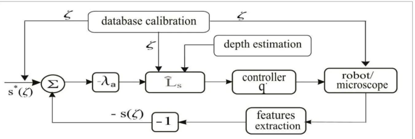
3. Multiscale Image-Based Visual Servoing for MEMS Micromanipulation
When several degrees of freedom have to be controlled, the visual servoing is achieved using an exponential decrease of the task function as presented in Chaumette et al. [9, 10]. The multiple scale paradigms are introduced by explicitly modeling the scale factor and the focal length as functions of the magnification or zoom factor [11]. A similar solution (multiple scale visual servoing) is developed in Devanathan et al [12]. It consists in combining two loops: a feedback from a macroscopic view (standard scope) to focus in the area of interest and a feedback from a microscopic view to actually perform the MEMS handling. Unlike this approach where the authors use two imaging systems to associate the global view to the local view of the scene, we propose a new approach where only one imaging system (videomicroscope equipped with variable and controlled zoom and focus) is used to perform a multiple scale visual servo.
The multiscale calibration performed links the scale factor k with the zoom factor ȗ according to the
following polynomial relation:
10 9 1 2 11
[ , ][ , , ,1]'
1 2 11
( ,c c c ) are the polynomial coefficients. Consequently, the focal length (f ) and the feature points
s(ȗ) are functions of the zoom factor (ȗ). Let s(ȗ) and s*( )ζ be the current and desired value of the set of selected visual feature points, respectively. The velocities ( s ) of those visual features are linked to the relative velocity of the camera/scene, v, by the following equation:
s f
s = L (s, Z , )ζ
v
(10)where L is the interaction matrix and (v), the kinematic screw, is given by the following formula: s
x y z x y z
v = (v , v , v , w , w , w ) (11)
andZ represents the depth information of the object expressed in the camera frame. A depth-from-f
focus approach computes this information [11]. Then the interaction matrix for the coordinates x and y
can be written as:
2 s 2 1 ( ) 0 ( ) ( ) 1 ( ) ( ) L ( , , , ) 1 ( ) 0 1 ( ) ( ) ( ) ( ) f f f f f x x y x y Z Z x y Z y y x y x Z Z
ζ
ζ
ζ
ζ
ζ
ζ
ζ
ζ
ζ
ζ
ζ
− § − − · ¨ ¸ ¨ ¸ = ¨ − ¸ + − − ¨ ¸ ¨ ¸ © ¹ (12)Let e be the error between the current position s(ȗ) and the desired position *
( )
s ζ .
*
e=s( ) s ( )ζ − ζ (13)
Considering an exponential decrease of the error, we have:
e= − λe (14)
That leads to the following control law:
s
v= −λL e (15)
whereλ is a positive gain. For a better convergence (good speed and without overshot) of e , the gain
is adapted to the value of e according to the following formula:
||e||
max min min
( ) exp ρ
λ= λ −λ − +λ (16)
where λmax and λminare respectively the maximum and minimum values of λ. The parameter ȡ allows
the tuning of the decreasing rate of the error exponential decrease.
Fig. 1. The function chart of multiple scale image-based visual servoing
4. Pose-Based Visual Control for MEMS Microassembly
Microassembly is a delicate operation because in addition to the stages of MEMS handling described in the previous section, it requires a much more complicated task which is an insertion task. The latter represents the fitting together of two or more simple MEMS in order to build 3D solid MEMS. This task requires the control of the position and orientation in space of the involved microparts. In this case, image-based visual control (or 2D visual servoing) is not relevant when pose-based visual control (also known as 3D visual control) is natural and relevant to perform that task.
MEMS robotic assembly has been well studied in the literature [1, 2, 13, 14, 15, 16]. In most cases, image-based visual servoing solutions were implemented. However the latter have shown some incontrovertible limits: the weakness of the field-of-view of the photon videomicroscope, the occlusion of the field by the robotic components and especially the ambiguity of MEMS position and orientation because of the 2D dimension of the images. Pose-based visual control appears to be the convenient solution to the issue of MEMS assembly. By implementing together a 3D tracking by CAD (Computer-Aided Design) models and control of targets, a solution is obtained which resolves the problem of ambiguity: the resolvability of the imaging system is increased as demonstrated by Nelson [13]. The impact of occlusions is reduced also since the 3D tracking is robust to occlusions. Except the papers of Feddema et al. [14] and Yesin et al. [13], no publication has never really implemented the assembly of MEMS by means of CAD model-based tracking and control. The law control presented in these papers is of the type 3D look and move. As opposed to these works, we developed a control law using a form of 3D interaction matrix which is faster and more stable compare to the look and move approach.
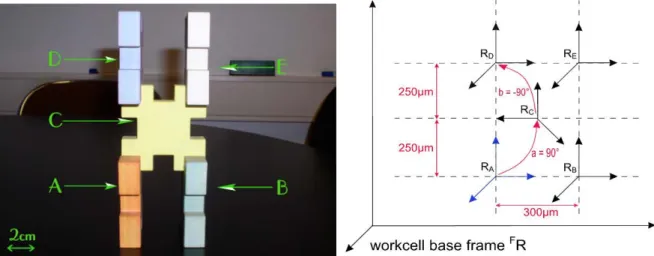
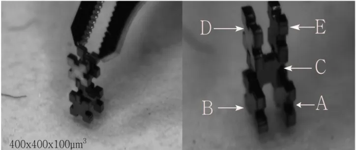
Let us consider the example of an assembly task of five simple MEMS {A, B, C, D and E} to build a complex and solid 3D MEMS as illustrated by Fig. 2. The insertion tolerance of two microparts is less than 3 µm. The precision criterion is of great importance in the approach as well as the time required to complete the full assembly.
Fig. 2. An assembly operation for macroparts. Fig. 3. Desired positions of each micropart to assemble
Fig. 3 shows the 3D positions of the different frames: R ,R ,R ,R and R linked to each MEMS. A B C D E
Let us define, for example, the rigid transformation between a frame Ri and a frame Rj by a
homogenous matrix iMj defined as:
R t M 0 1 i i i j j j § · = ¨ ¸ © ¹ (17) whereiR
j is the rotation matrix and t i
j the translation vector. It is also possible to note the pose by the
vectorir
j, (Eq. 18). A tracking algorithm VIsual Servoing Platform (VISP) developed by Marchand et
al. [16], [17] is used to compute the 3D poses of microparts tracked at real-time.
r ( t , u)
i i
j = j
θ
(18)where uθ is the axes and the angle of the rotation.
The equation that links the variation s of the visual feature s to the robot velocity in the robot reference frame ( , )v w F
Τ are given by:
3 3 3 3 3 3 w I 0 v t 0 J w u F np F
θ
× × × § · §= · § ·= ¨ ¸ ¨ ¸ ¨ ¸ © ¹ © ¹ © ¹ (19) with: w w J =L npRF (20)where {np} is the micro-object label and L is such that: w
-1 W
L θu = u θ (21)
3 3 3 3 * -1 3 3 w I 0 v (s s ) 0 J w F
λ
× × × § · § · = − − ¨ ¸ ¨ ¸ © ¹ © ¹ (22) * t t R u F F np np F npλ
θ
§ − · = − ¨¨ ¸¸ © ¹ (23)The robotic system presented in this paper includes two separate systems: a positioning platform and a
micromanipulator. For the positioning platform, we control three dof (xyș) and the control law
corresponding to this task is obtained by simplifying the previous relationship:
* x x * y y t t t t R u F np F x y θ
λ
θ
θ
§ − · § · ¨ ¸ ¨ ¸ = − ¨ − ¸ ¨ ¸ ¨ ¸ ¨ ¸ © ¹ © ¹ (24)In the same way, the control law defined in (25) ensures the control of the two dof (zij) of the micromanipulator: * R u z z F np t t z ϕ
λ
θ
ϕ
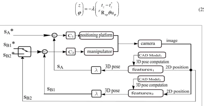
§ − · § · = − ¨ ¸ ¨ ¸ ¨ ¸ © ¹ © ¹ (25)Fig. 4. Function chart of the insertion by means of dual 3D visual control
Fig. 4 shows the corresponding chart of this approach in the case of two simple MEMS. The MEMS {A} and {B} are tracked by their CAD models and the robotic system is controlled by means of pose-based visual servo in order to achieve the insertion of {B} into {A}. It should be stressed that the positioning task of the different microparts between the end-effectors and the gripping of the micropart task are achieved by means of previous image-based visual servo.
The switching between the different 3D desired poses of the microparts on the 3D structure is computed automatically by the following relationship:
0
M M * M
F n
where l (l = {A, B, C, D and E}) is the micro-object label and M represents the desired position of the 0
first micropart {A} which is defined manually. Mn
m is the passage matrix between the desired position
of micropart {n} and micropart {m}.
The switch between the different tasks of positioning (control of the positioning platform) and insertion (control of the micromanipulator) for successive microparts is done when the threshold of translation and rotation error is reached ([ et <1µm] and [ er <0.5° ]). The same threshold is applied for
all the tasks.
The desired position of the first micropart {A} is defined manually (FMA) (Initialization step). When
{A} is perfectly positioned ([ et <1µm] and [ er <0.5° ]), the final position of the second micropart is
computed automatically using Eq. (25). A translation of 300 µm along the z axis is made from the pose
of the micropart {A}. The matrix passageFMBA between the final pose {A} and the final pose {B} is
given by the following formula:
B A 1 0 0 0 0 1 0 0 M 0 0 1 300 0 0 0 1 F § · ¨ ¸ ¨ ¸ =¨ ¸ ¨ ¸ © ¹ (27)
The sequence is repeated for the desired position of micropart {B} and {C} using Eq. (28). It includes a rotation of
α
= 90° around the vertical axis z, a translation of -250 µm along y and 150 µm along x.C A 0 0 1 0 0 1 0 250 M 1 0 0 150 0 0 0 1 F § · ¨ − ¸ ¨ ¸ =¨ ¸ − ¨ ¸ © ¹ (28)
The transformation between the final position of the micropart {A} and the fourth micropart {D} is given by the following relationship:
D A 1 0 0 0 0 1 0 500 M 0 0 1 0 0 0 0 1 F § · ¨ − ¸ ¨ ¸ = ¨ ¸ ¨ ¸ © ¹ (29)
The last desired pose corresponding to micropart {E} is given by the rigid transformation in Eq. (30). It consists of two translations of -250 µm and -500 µm respectively along x and y.
E A 1 0 0 250 0 1 0 500 M 0 0 1 0 0 0 0 1 F − § · ¨ − ¸ ¨ ¸ =¨ ¸ ¨ ¸ © ¹ (30)
5. Experimental Setup
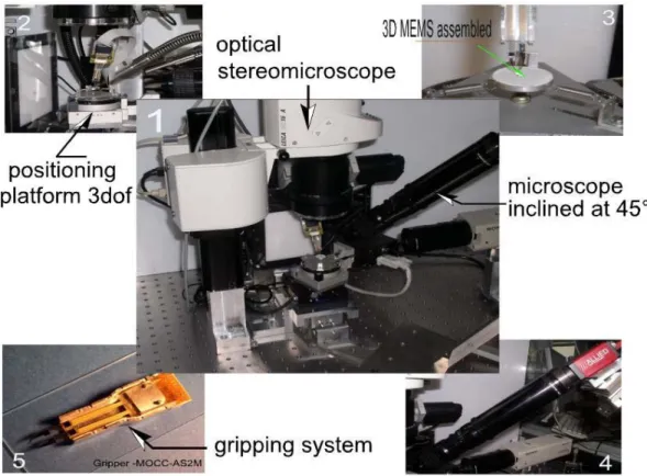
To validate the approaches and concepts proposed in this paper, a microassembly workcell was designed, as shown in Fig. 5. From a mechanical point of view, the station consists of five dof: three
dof are dedicated to the positioning platform (two linear stages xy and one rotating stage ș), the
second part is a micromanipulator equipped with two dof (one vertical linear stage z and one rotating stage ij tilted at 45° from the vertical one). The micromanipulator supports four dof (y1y2z1z2) gripping
system which consists in a piezoelectric driven two-finger gripper. A detailed description of this gripper can be found in [18]. An optical videomicroscope equipped with a computer controlled zoom and focus (MZ16A from Leica) is used for the multiple scale image-based visual control. The
magnification ranges from 0.71× to 11.5×. The minimum field-of-view is 700 µm × 900 µm. The
depth-of-field varies between 0.035 mm and 2.9 mm. Another monochrome optical videomicroscope
(Navitar zoom 6000 with 1× adaptor and a CCD camera) is used to perform the MEMS assembly
using the pose-based visual servoing presented in section 4. Its characteristics are 4.5× magnification,
a depth-of-field of 0,09 mm. The vision system (optical videomicroscope) is tilted at 45° from the word frame. This configuration is chosen in order to improve the perspective view of the MEMS during the various steps of assembly.
Fig. 5. Global and local views of each part (positioning platform, the compliant support of the micro-objects, the gripping system and the imaging system) of the assembly workcell
6. Experimental results
6.1. Multiscale Calibration Results
As a consequence of the weakness of the depth-of-field, a 3D calibration sample cannot be used; the sample is reduced to a planar object that should be almost parallel to the lens. A videomicroscope is
heavy and cumbersome and is thus not easy to manipulate. These constraints complicate the calibration. On the other hand, the presence in the set-up of accurate motion sources as xyz stages enables the performing of accurate motions of the plane calibration sample and contributes to facilitate the calibration.
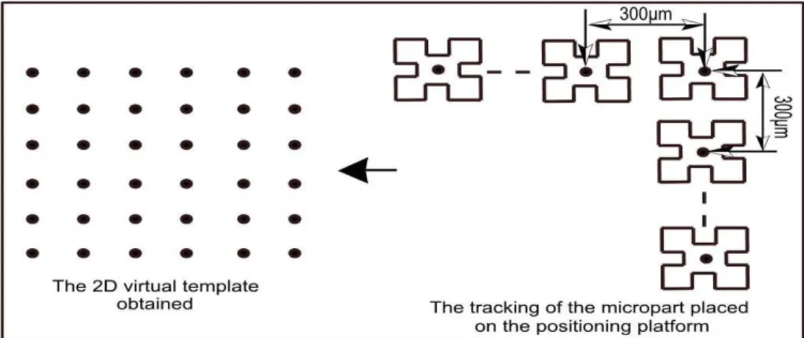
Instead of using a real sample [3] or virtual points [7] as encountered in the literature, we use the power of image processing (auto-correlation algorithm): the centre of a micrometric micropart is tracked in the images of the scene, as depicted in Fig. 6. The micropart is moved accurately by a xyz stage, so its central position in the scene is known with high accuracy. These positions are used to synthesize a virtual image which is used in the algorithm presented before. This approach enables a high accuracy in the computing of the model parameters. The approach is also simple, since it does not require the micromachining of any pattern. The components to assemble are directly used.
Fig. 6. Virtual pattern construction method using image processing algorithm based on an auto-correlation detection of the silicon micropart manipulated
Fig. 7.Scale factor according to zoom factor
Fig. 6 shows steps of x and y displacements of 300 µm performed for the generation of the 2D virtual
pattern used to calibrate the imaging system. Fig.7 represents the evolution of the scale factor k(ȗ)
according to the zoom factor (ȗ). The approximation of this function by a polynomial function using MatLab gives a polynomial P of degree ten.
For a zoom position of 38×, the computation of the calibration matrix gives: 3146.3 0 512.5 0 3146.3 385.5 ( ) 0 0 1 K pixels § · ¨ ¸ = ¨¨ ¸¸ © ¹ (31)
According to the equations, the following values are extracted:
3 3.6444 11.466 10 x y k k k µm f µm = = = = × (32)
and the extrinsic parameters are:
88.73 27.26 4.01 [822 963 13156]' v T mm
α
β
γ
= ° ° = − ° ° ® = ° ° ° = ¯ (33)6.2. MEMS Micromanipulation Results and Discussions
The multiple scale image-based visual servoing presented in section 3 is validated by a basic micromanipulation task which consists in a pick and place of silicon microparts of
400µm×400µm×100µm. The pick and place cycle is decomposed in subtasks such as: detection of the
micropart, aligning + increasing the scale, positioning (between the gripper end-effectors) + increasing the scale, centering + increasing the scale, opening the gripper, descent of the gripper, closing the gripper, ascent of the gripper with the micropart + decreasing the scale, transfer of the micropart to the target + decreasing the scale, descent of the gripper + decreasing the scale, release of the micropart + decreasing the scale and the cycle is ended by a return of the gripper to the original location. Several pick and place cycles are performed with different configurations of the initial position of the micropart. The results obtained are presented for different points:
• A success rate for several pick and place cyclic has been calculated (72% of success) • The robustness of partial occlusions of the micropart tracked during the control is proven • A high x positioning accuracy is obtained (~1.4 µm), such quality precision of the orientation is
obtained (~0.5°)
• The good convergence (without overshot) of the control law (multiple scale visual servoing) is ensured using the adaptive gain in Eq. (16)
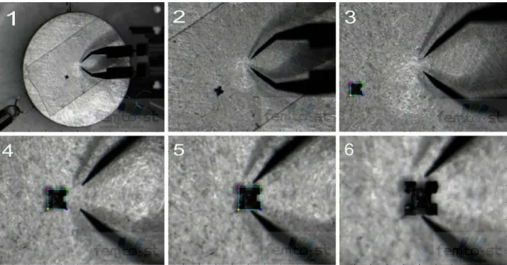
Fig. 8 illustrates the sequence of the basic tasks executed using the developed visual servoing. Fig. 8.1 shows the initial position of the micropart, Fig. 8.2 shows the micropart alignment task, and Fig.8.3-8.5 illustrate the positioning task + increasing scale. The image sequence is ended with a centering task of the micropart between the gripper end-effectors for gripping task. The gripping operation on the micro-object is controlled using the vision sensor, as the gripper is not equipped with a force sensor yet. It consists in a 2D tracking of the gripping tips and a look and move control is developed to ensure the gripping task.
Fig. 8. Several shots during the studied sequence (detection, alignment, positioning and cantering).
Fig. 9 shows several results of different automatic micromanipulation of silicon micropart, metal microball and optical microfiber. Fig. 9.1 and 9.2 show the respective side views of a metal microball
of 200 µm diameter and a square silicon micropart of 400 µm×400 µm×100µm handled using the
multiscale image-based visual control. Fig. 9.3 illustrates micromanipulation of an optical microfiber of 125 µm of diameter using the same control law.
Fig. 9. Examples of different microparts (metal ball, square silicon micropart, optical fiber) used to validate the concepts and approaches proposed above
6. 3. MEMS Microassembly Results and Discussions
In this subsection, we show that the microassembly MEMS is possible using a 3D visual control associated to a high precision CAD model-based tracking. It has been proven in the previous sections that the complex assembly illustrated in Fig.10 is impossible to be achieved in tele-operation mode (with a joystick), even with a human operator with enough experience in tele-operated handling. Therefore, an automatic approach is more efficient. Promising results are obtained, especially in terms of accuracy, robustness, repeatability and the time required to achieve a full assembly (~40 seconds to perform positioning and insertion of two micro-objects). The mean positioning error (translation) is less than 2.04 µm and the mean orientation error (angular) is less than 0.48 °. The high quality of the
results allows performing MEMS assemblies with an insertion tolerance (mechanical play) less than 3
µm. Therefore, solid MEMS can be assembled without any external joining (glue or welding).
Fig. 10. Sequence of images taken during the assembly process.
Fig. 11. Images of the solid and complex 3D microassembly (five microparts, 3 levels) obtained.
Fig. 10 represents a sequence of images from the optical videomicroscope system showing the process
of the automatic microassembly of five silicon microparts of size of 400µm×400µm×100µm. Fig. 10a
illustrates the first step which concerns the tracking and the positioning of the micropart {A}. Fig. 10b presents the tracking and placing of the micropart {B}. Fig. 10c shows the tracking and the positioning of the both microparts {[A+B]}, while Fig. 10d depicts the tracking and insertion of the micropart {C} into the micropart {[A+B]}. Fig. 10e presents the tracking of the micropart {A} and the positioning of the microparts {[A+B+C]}. Fig. 10f depicts the tracking and the insertion of the micropart {D} into the microparts {[A+B+C]}. Finally, Fig. 11 illustrates the solid and complex 3D microassembly performed.
7. Conclusions
The robotic microassembly task is the assembly of micrometric (submillimeter) parts to works multicomponents products by means of a robotic system in conjunction with a gripping system and an imaging system. When the imaging system delivers images from which a lot of information can be extracted, the problem is that high resolution (local view) and low resolution (global view) information must be catched at the same time. An interesting solution to the problem is the multiple scale imaging using a photon videomicroscope equipped with a tunable zoom. This paper deals with the multiscale modelling of the variable zoom of the photon videomicroscope as well as the manipulation and assembly of MEMS by means of visual control (image and pose-based).
It was shown that the functioning of controllable zoom videomicroscope can reasonably be described by a simplified projective model. The first simplification is relative to the omission of distortions because of the weak values of their coefficients. The second simplification consists in considering that the scale factor along the axis x and y is equal. Finally the (intrinsic) parameters become the focal
length f, the scale factor k, the principal point coordinates (xo,yo). The concept of multiple scale
modelling is introduced through the zoom factor ȗ whose mathematical relation with the scale factor k is claimed: k is a polynomial of ȗ. The following approach of calibration is proposed: the polynomial
k(ȗ) is accurately estimated by changing the zoom factor ȗ and computing the corresponding scale
factor k. The linear projective model is computed using a usual calibration approach with a virtual calibration sample. The calibration results are used to perform robotic MEMS manipulation by means of image-based visual control and assembly by means of pose-based visual control. The multiple scale image-visual servoing achieves a pick and place including basic tasks like aligning, positioning, centring, and gripping. The results prove the relevance of the concepts. A 72% success rate of the different pick and place performed is obtained. Indeed, the failure rate of 28% is mainly the results of physical phenomena (adhesion forces) and hardly a consequence of control error or occlusions.
The MEMS assembly (assembly of five silicon microparts) is performed by a pose-based visual control. It was shown that the precision obtained during the experimental validation of this approach is good and it is sufficient to consider assembling solid and complex MEMS without external solidarization such as gluing or welding. This accuracy is less than 2.08 µm along the translation motions and 0.48 ° for the orientation motions. The automation of MEMS assembly using a visual sensor feedback permits assembly tasks which was impossible to achieve in teleoperating mode for a human operator. In addition, the time required for MEMS assembly is divided by 15 by this automatic approach developed.
Acknowledgements
This work is partially conducted with financial support from the project Hybrid Ultra Precision Manufacturing Process Based on Positional and Self assembly for Complex Micro-Products (HYDROMEL NMP2-CT-2006-026622) funded by the European Commission.
References
[1]. W.T. Sun and T.C. Chin, Image-based visual servo for micromanipulation a view and multiple-scale approach, International Symposium on Micro-Nanomechatronics and Human Science, November 2004, pp. 341-346.
[2]. Stephen Ralis, Barmeshwar Vikramaditya, and Bradley J. Nelson, Micropositioning of a weakly calibrated microassembly system using coarse-to-fine visual servoing strategies, IEEE Transactions on Electronics Packaging Manufacturing Vol. 23, Issue 2, 2000, pp. 123-131.
[3]. Y. Zhou and B.J. Nelson, Calibration of a parametric model of an optical microscope, Optical Engineering Vol. 38, No. 12, 1999, pp. 1989–1995.
[4]. R.Y. Tsai, A versatile camera calibration technique for high-accuracy 3d machine vision metrology using off-the-shelf tv cameras and lenses, IEEE Journal of Robotics and Automation, Vol. RA-3, No. 4, 1987, pp. 323–344.
[5]. K. Tarabani, R.Y. Tsai, and D.S. Goodman, Calibration of a computer controlled robotic vision sensor with zoom lens, CVGIP, Vol.59, Issue 2, March 1994, pp. 226-241.
[6]. P. Sturn, self-calibration of a moving zoom-lens camera by precalibration, IVC, Vol.15, Issue 08, 1997, pp. 583–589.
[7]. M. Ammi, V. Fremont, and A. Ferreira, Flexible microscope calibration using virtual pattern for 3-d telemicromanipulation, IEEE International Conference on Robotics and Automation, April 2005, pp. 3888-3893.
[8]. B. Tamadazte, S. Dembélé, and N. Le Fort-Piat, A multiscale calibration of a photon video microscope for visual servo control: Application to micromanipulation, IEEE International Workshop on Robotic and Sensors Environments, Ottawa, Canada, October 2008, pp. 29-34.
[9]. F. Chaumette and S. Hutchinson, Visual servo control, part 1: Basic approaches, IEEE Robotics and Automation Magazine, Vol.13, No. 4, 2006, pp. 82-90.
[10]. B. Espiau, F. Chaumette, and P. Rives, A new approach to visual servoing in robotics, IEEE Transactions on Robotics and Automation, Vol. 8, Issue 3, 1992, pp. 313–326.
[11]. B. Tamadazte, S. Dembélé, G. Fortier, and N. Le Fort-Piat, Automatic micromanipulation using multiscale visual servoing, IEEE Conference on Automation Science and Engineering, Washington, USA, August 2008, pp. 977-982.
[12]. R. Devananthan, S. Wenting, C.T. Chai and A. Schacklock. Multi View and Multi Scale Image Based Visual Servo For Micromanipulation, Studies in Computational Intelligence (SCI), Vol.8, 2005, pp. 105– 133.
[13]. K. Berk Yesin and B.J. Nelson, Robust cad model-based visual tracking for 3d microassembly using image space potentials, IEEE International Conference on Robotics and Automation, (ICRA’04), New Orleans, USA, April 2004, pp. 1868–1873.
[14]. John T. Feddema and Ronald W. Simon. Visual servoing and CAD-driven microassembly, IEEE Robotics and Automation Magazine, Vol. 5, Issue 4, 1998, pp. 18–24.
[15]. Dan O. Popa and Harry E. Stephanou, Micro and mesoscale robotic assembly, Journal of Manufacturing Process, Vol. 6, Issue 1, 2004, pp. 52–71.
[16]. E. Marchand, F. Spindler, and F. Chaumette, ViSP for visual servoing : a generic software platform with a wide class of robot control skills, IEEE Robotics and Automation Magazine, Vol.12, No. 4, 2005, pp. 40– 52, Special Issue on "Software Packages for Vision-Based Control of Motion", P. Oh, D. Burschka (Eds.). [17]. A.I. Comport, E. Marchand, M. Pressigout, and F. Chaumette, Real-time markerless tracking for
augmented reality: the virtual visual servoing framework, IEEE Transactions on Visualization and Computer Graphics,Vol. 12, No. 4, 2006, pp. 615-628.
[18]. J. Agnus, P. Nectoux, and N. Chaillet, Overview of microgrippers and design of a micromanipulation station based on mmoc microgripper, IEEE International Symposium on Computational Intelligence in Robotics and Automation, Finland, 2005, pp. 117-123.