HAL Id: hal-01709497
https://hal.archives-ouvertes.fr/hal-01709497
Submitted on 4 Dec 2019
HAL is a multi-disciplinary open access
archive for the deposit and dissemination of
sci-entific research documents, whether they are
pub-lished or not. The documents may come from
teaching and research institutions in France or
abroad, or from public or private research centers.
L’archive ouverte pluridisciplinaire HAL, est
destinée au dépôt et à la diffusion de documents
scientifiques de niveau recherche, publiés ou non,
émanant des établissements d’enseignement et de
recherche français ou étrangers, des laboratoires
publics ou privés.
Spallation Process of Thermally Grown Oxides by
In-Situ CCD Monitoring Technique
Qi Yu-Hong, Philippe Lours, Yannick Le Maoult
To cite this version:
Qi Yu-Hong, Philippe Lours, Yannick Le Maoult. Spallation Process of Thermally Grown Oxides by
In-Situ CCD Monitoring Technique. Journal of Iron and Steel Research, International, Elsevier, 2009,
16 (6), pp.90-94. �10.1016/S1006-706X(10)60034-9�. �hal-01709497�
Spallation Process of Thermally Grown Oxides by
In-Situ CCD Monitoring Technique
QI Yu-hong' • Philippe Lours", Yannick Le Maoult"
(1. Materials Science and Engineering Department, Dalian Maritime University. Dalian 116026. Liaoning. China; 2. Research Centre on Tools. Materials and Processes. Ecole des Mines. 81013 Albi , France)
Abstract: In cooling process of Fe-Cr-Al alloy oxidized at 1 300 "('. the effect of cooling speed and exposure time on oxide spalled area fraction and successive variety of the spalled region were studied by investigating evolvement of the thermally grown oxide using in-situ CCD monitoring technique. The results showed that oxide spallation can be re-strained by controlling cooling speed and the critical temperature drop of spallation initiation which is closely related to the oxide thickness or exposure time. and the spallation process of a little region may be described in more detail as two routes: from the oxide/substrate interface micro-decohesion , micro-buckles. buckle spreading. buckle crack to spallation and from the interface rnicro-decohesion , micro-buckles. buckle crack and spallation to the residual oxide decohesion and spallation.
Keywords: in-situ CCO monitoring technique; spallation; thermally grown oxide; Fe-Cr-Al
High temperature alloys are protected from rap-idly oxidizing degradation by the formation of slow growing oxide scales. However. brittle oxides. the weak interfacial adhesion and the thermal stresses in oxide can result in cracking and detachment or spall-ation. The failure destroys the protective function of oxides. Therefore. evaluation and prediction of the scale crack and spallation is of great importance to understand the failure mechanism of oxide scale and to select correctly material and develop new materi-als under the service environment!I - I ] . Some
meth-ods and techniques of evaluating adhesion of the ox-ide scales to substrate have been studied. These methodsL5
- 9] are classified into mechanical testing
techniques which include direct pulling. double beam bending. scratch tests. indentation technique and spallation monitoring techniques which include thermogravimetric analysis. acoustic emission. Ra-man spectroscopy and CCO monitoring. Pulling. scratch and microindentation tests are convenient and easy to perform. but only useful for relative comparisons within a given system of some limited alloys. Double beam bending techniques can provide
accurate information on the strength or fracture re-sistance of the interface. However. an adhesive usually has to apply between the fixture and oxide surface. This not only complicates the analysis. but also limits the strength of the interface that can be measured. Thermogravimetric analysis method is to measure the temperature and gross oxide weight gain at initia-tion of oxide spallainitia-tion during cooling. Acoustic emis-sion technique has been used as an in-situ monitoring of crack initiation and development of oxide scales on metal. CCO monitoring is a new in-situ technique that focuses on the successive variational morphology and temperature of whole surface during specimen cooling. Spallation monitoring techniques can be used to study the spallation behavior of oxide film and interfacial fracture energy of oxide/metal by mo-nitoring the spallation process of oxide scales and temperature drop during cooling.
The purpose of present work is to study the effect factors and mechanism of oxide spallation by investigating spallation behavior of the whole sur-face in specimen cooling process using in-situ CCO monitoring technique.
Foundation Item: Item Sponsored by the Scientific Research Foundation for the Returned Overseas Chinese Scholars Biography: QI Yu-hongCl963-). Female. Doctor. Professor; E-mail: yuhong_qi@dlmu.edu.cn ;
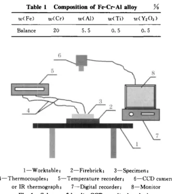
Table 1 Composition of Fe-Cr-AI alloy %
2
Results and Discussion
900 300 500 700
Exposure timeJh
5L-- ---J
100
Fig. 2 Oxidation kinetics curves
35
r---...,
267 h , 362 hand 819 h and the oxide thickness are 14.91, 17.86, 19.71 and 31. 13 p'm, respectively. The oxidation kinetics curve is shown in Fig. 2, from which oxide thickness increases with oxide exposure time t, Eqn. (1) can be obtained by curve fitting which accords with a parabola relationship.
1.034tO.506 (1)
2. 2 Effect of cooling speed
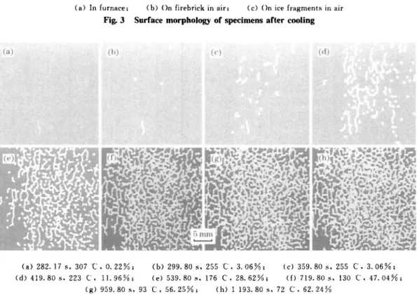
During the sample cooling, the oxide film is possible to crack and spall under the driving force of compressive stresses that are produced from oxide growth and shrinking difference between oxide film and substrate due to their different thermal expan-sion coefficients. The initial temperature drop and surface area fraction of oxide spallation are mainly relative to the oxidation temperature, the cooling speed and the exposure time as well as the intrinsic mechanical properties of the substrate, the oxide and their bonding interface. The surface of speci-mens oxidized at 1 300 'C for 267 h is observed at ambient temperature after cooling in furnace, on firebrick in air (Fig.1) and on ice fragments in air re-spectively. When cooling in furnace, no spallation oc-curred, but there are some cracks on oxide surface [Fig. 3 (a)]. Serious spallation occurred for the specimen cooled on firebrick in air [Fig. 3 (b) ] , whereas near fully spallation when cooling on ice fragments in air [Fig. 3 (c)]. Therefore, cooling speed has an obvious effect on oxide spallation. Dur-ing coolDur-ing, the spallation of oxide film is mainly due to the compressive stress in oxide caused from mismatch of thermal expansion coefficients between substrate and oxide. The more rapid the cooling speed is, the greater the stress is.
Fig. 4 shows the scale spalled morphology of the specimen cooled on firebrick in air. When the surface temperature falls to about 307 'C [Fig. 4 (a)
J,
0.5 0.5 5.5 wCAI) 20 wCCr) wCFe) Balance
1
Experimental
I-Worktable; 2-Firebrick; 3-Specimen;
4-Thermocouples; 5-Temperature recorder; 6-CCD camera or IR thermograph; 7-Digital recorder; 8-Monitor
Fig. 1 Scheme of in-situ CCD monitoring device The chemical composition of Fe-Cr-Al high temperature alloy investigated in this paper (mass percent) is given in Table 1. The oxidation experi-ment was performed in a muffle furnace at 1 300 'C for 194 h , 267 h , 362 hand 819 h. Specimens with 8 mm thick and 30 X 30 mrn" square were polished and ultrasonically cleaned in acetone prior to oxida-tion. The scheme of in-situ CCD monitoring the spallation of oxide scales during cooling is shown in Fig. 1. After oxidation, the specimen is removed out and put on the firebrick on which two thermocouple wire ends are fixed to keep good contact with the back of specimen. Monitor, digital recorder and temperature measurement recorder are turned on simultaneously. CCD camera recorded the surface morphology at a second of 30 frames and infra-red thermograph re-corded temperature distribution of the specimen sur-face. Image analysis is used to evaluate the spalled area of the oxide scales. Hardness was tested by Buehler MICROMET 2001 Vickers microhardness tester and morphology and thickness of oxide were examined by scanning electron microscope.
2. 1 Oxidation kinetics
(a) In furnace; (b) On firebrick in air; (c) On ice fragments in air
Fig. 3 Surface morphology of specimens after cooling
(a) 282. 17s , 307 ·C. 0.22%; (b) 299.80s. 255C. 3.06%; (c) 359.80s , 255 C. 3.06%; (d) 419.80s , 223 C. 11. 96%; (e) 539.80s , 176 C. 28.62%; ({) 719.80s , 130 C. 47.04%;
(g) 959.80 s , 93 C. 56.25%; (h) 1 193.80 s , 72 C. 62.24%
Fig. 4 Scale spalled morphology of specimen oxidized at 1 300 't for 267 h during cooling the oxide film begins to spall in the vermiculate
mor-phology. The oxide spalied area increases subsequently with the specimen temperature falling. The spalled sites are random, but the spalled initial temperature is higher and the spalled area fraction is more in speci-men centre than in specispeci-men edges. The morphology of most spalled region is vermiculate and round.
Surface temperature distribution of cooling to 100 s for the specimen oxidized at 1 300 'C for 267 h are recorded by infra-red thermograph (Fig. 5). The cooling curves of spot 1, 2, 3 and 4 in Fig. 5 are drawn in Fig. 6 respectively. According to Fig. 5 and Fig. 6, there is no spallation in spot 3 in which the cool-ing curve is smooth, and the scales on spot 1, 2 and 4 have been spalled off in which the cooling curves are dis-continuous. The sharp drop points show the onset of scale spallation from which the temperature and time of scale spallation initiation at spot 1, 2 and'4are 520 'C, 15 s , 515 "C, 20 sand 396 "C. 94 s , respectively.
Therefore. formation time. shape. size and po-sition of oxide spallation region are random for the same specimen. which depend on the distribution of compressive stresses in oxide film.
o 100 200 300 400 Cooling tirne/s
Fig. 6 Cooling curves of spot 1, 2, 3 and 4 in Fig. 5
2. 3 Effect of exposure time
The area of scale spallation increases with tem-perature falling for four samples oxidized at 1 300 'C for 194 h , 267 h , 362 hand 819 h. The variation curves of the area spalled with specimen temperature are shown in Fig. 7. During cooling when oxide film is cooled to some temperature, that is, the tempera-ture of spallation initiation, the scale spallation be-gan and the area spalled increase rapidly with speci-men cooling. The spallation ended at about 60- 80 ·C. The area, initial temperature and end temperature of scale spallation are mainly related to the oxide thick-ness, and increase with oxide thickness increasing. The critical temperature drop 6.Tc of spallation initi-ation, that is the difference between oxide tempera-ture and initial spallation temperatempera-ture, is an impor-tant parameter to characterize the adhesion of oxide film which is closely related to the scale thickness or oxide exposure time. The 6.T; value is
corre-spondingly 1 069, 1 035, 1 005 and 768 for the spec-imens with oxide thickness of 14. 91 11m, 17. 86 11m,
Fig.7 Variation of area spalled with specimen temperature
19.71 11m and 31. 13 11m. The curve fitting equation of 6.Tc with is expressed as follows:
6.Tc=1 127+3. 47f (2)
An alternative form of Eqn, (2) is obtained by substituting Eqn, (l) for
6.Tc=1 127+3.32to.506 _ 0 .49tl.12 (3)
Eqn, (3) can be used to predict initial spallation temperature of Fe-Cr-AI alloy after any exposure time at high temperature 1 300 ·C.
2. 4 Microstructure of spalled region and spallation mechanism
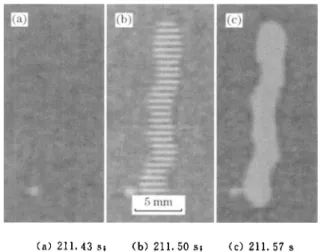
When the specimen oxidized at 1 300 'C for 362 h is cooled to 211 s , the successive evolvement of a spalled region is shown in Fig. 8. No spallation oc-curred in the 13th frame [Fig. 8 (a)] at 211 s , whereas in the 15th frame [Fig. 8 (b)], there is a spalled region which consists of many parallel strips of non spalled oxide film, but in the 17th frame [Fig. 8 (c)], the parallel oxide strips peel fully off. The similar phenomena also occurred in other three specimens. The articles on such oxide spalling process have not read yet.
Evans et al[6.7] considered that there are two typical processes of spallation for thermally grown oxide film under compressive stresses.
If
oxide/ metal interface has a high adhesive strength relative to the cohesive strength of the oxide, cracking of the oxide will take place before decohesion , whereas poor in-terface adhesion will result in decohesion before ox-ide cracking. In this work, more detailed spallation process has been observed (Fig. 8) by in-situ CCD monitoring. Therefore, spallation mechanism may be described in more detail as Fig. 9.(a) 211.4351 (b) 211.5051 (c) 211.57s
Fig. 8 Successive evolvement of surface spalled region for specimen oxidized at 1 300 "C for 362 h during cooling
Fig.9 Sketch of spallation process for Fe-Cr-AI alloy
men centre than in specimen edges.
(3) The critical temperature drop
t:..
T; ofspall-ation initispall-ation is closely related to the scale thick-ness or oxide exposure time t that may be ex-pressed as follows:
t:..Tc = l 127+3. 47f
t:..Tc = l 127+3.32t,,·506_0.49tl.12
The equations can be used to predict and control the spallation of thermally grown oxides.
(4) The spallation process of a little region may be described as micro-decohesion - microbuckles -buckle spreading- -buckle crack- spallation or micro-decohesion-s-micro-buckles-> buckle crack and spall-ation-the residual oxide decohesion and spallation.
(c2) (d2)
/
? fV
(e)n-z:V
(el) (dl)Oxide _ _WI/77ll/IUll; (a) Substrate - -
t
TTZ1LlrtZ:!:zta
(b)/
'"
+
l
The thermal stress in oxide leads to many local-ized micro-decohesion and micro-buckles [Fig. 9 (a)
to (b)] in a little region; then if oxide is stronger. the buckles may spread to all region into a large buckle [Fig. 9 Ccl ) to (d1)] under compressive stress and the buckled scale produce cracks under tensile stress and lead to spallation [Fig. 9 (d l ) to (e)]. whereas the weak oxide buckles will result in crack and spalation [Fig. 9 (c2) to (d2) ] under ten-sile stress. subsequently decohesion and spalation [Fig. 9 (d2) to (e)] take place for the other oxides between the buckles under compressive stress. This work provides a good support for Evans' buckling spallation rou,el 7J •
3
Conclusions
( 1) During oxide spallation process caused by air cooling. temperature. time. shape and size of any spalled region can be obtained by in-situ CCD monitoring method.
(2) The oxide spalled area increases with de-creasing the specimen temperature. The spalled sites are random. but the spalled initial temperature is higher and the spalled area fraction is more in
speci-References:
[1 J Evans H E. Stress Effects in High Temperature Oxidation of Metals
[n.
International Materials Reviews. 1995. 40(\): I. [2J McCartney I. N. Modelling Scale Failure in Tension (Fractureand Spallation) [JJ. Materials at High Temperatures. 2005. 22(\-2): 167.
[3J Bamba G. Wouters Y. Galerie A. et at. Thermal Oxidation Kinetics and Oxide Scale Adhesion of Fe-15Cr Alloys as a Function of Their Silicon Content [J]. Acta Materialia , 2006. 54(15): 3917.
[4 J Evans H E. Spallation Models and Their Relevance to Steam-Grown Oxides[j]. Materials at High Temperatures. 2005. 22 (1-2): 155.
[5J HouI'Y. Saunders S R J. A Survey of Test Methods for Scale Adhesion Measurement
[n.
Materials at High Temperatures. 2005.22(\-2): 121.[6J Evans H E. Spallation of Oxide From Stainless Steel Agr Nu-clear Fuel Cladding: Mechanisms and Consequences [J]' Mater Sci Technol , 1987.4: 415.
[7J Nishiyama Y. Kitamura K. Kudo T. er at. In Situ Evaluations for Spallation of CrzO, Scale by AE and Raman Spectroscopy
[n.
Journal of the Japan Institute of Metals. 2007. 7)( I): 55 (in Japanese).[8J Lours P. Maoult Y. Ade D. er aJ. Direct Examinations of Ox-ide Scales Upon Cooling: A New Way to Analyse OxOx-ide Scale Spallation [JJ. Materials Science Forum. 2004. 461-464<II>: 639. [9J Lours P. Qi Y. Le Maoult Y. et at. In Situ and ex Situ Investi-gation of the Spallation of Thermally Grown Chides[n. Mate-rials Science Forum. 2007. 539-543(2): 1134.