Université du Québec
Institut National de la Recherche Scientifique Énergie, Matériaux et Télécommunications
A Comprehensive Study on Non-precious Metal Catalysts for
Proton Exchange Membrane Fuel Cells (PEMFCs)
Par Xiaohua Yang
Thèse présentée pour l’obtention du grade de Philosophiae doctor (Ph.D.)
en sciences de l’énergie et des matériaux
Jury d’évaluation
Président du jury et Prof. Fiorenzo Vetrone
examinateur interne INRS-EMT
Examinateur externe Prof. Mohamed Siaj
Université du Québec à Montréal
Examinateur externe Prof. Zhibin Ye
Concordia Université Directeur de recherche Prof. Shuhui Sun
INRS-EMT
I
ABSTRACT
Proton exchange membrane fuel cells (PEMFCs) are promising as a type of clean and efficient power source. The anodic hydrogen oxidation reaction (HOR) and cathodic oxygen reduction reaction (ORR) are cornerstone reactions for PEMFCs. Compared to HOR, the kinetics of ORR is more sluggish and requires much more catalyst, such as platinum (Pt), to achieve favorable overall performance. This configuration obviously brings the cost issue because Pt is scarce and expensive. To address this issue, great efforts have been devoted to developing highly active platinum group metal-free (PGM-free) catalysts for the ORR. Currently, the intrinsic activity of the state-of-the-art PGM-free catalyst (e.g. Fe/N/C catalyst) is comparable to Pt. Despite the great progress, several severe challenges still remain: (1) In order to achieve comparable activity and performance to Pt/C cathode under PEMFC operation condition, the high catalyst loading of Fe/N/C catalyst (e.g., 3-4 mgFe/N/C cm-2) is required. However, the high loading leads to a thick
Fe/N/C catalyst layer, which is nearly 10-fold that of the Pt/C catalyst layer (e.g., 100 μm vs. 10 μm), inevitably resulting in a severe mass-transport loss at high current densities. (2) Alongside the high catalytic activity, Fe/N/C catalyst is subject to fast decay. In fact, this unstable behavior is the common issue for the most reported PGM-free catalysts, especially the high-performance catalysts. The underlying decay mechanism has not been well understood yet. (3) Another obstacle is the protocol used so far for the evaluation of the catalyst stability. Owing to the diverse range of experimental conditions used in different labs, the published stability results are difficult to compare between lab to lab. The influence of the test protocols on the degradation mechanism of the catalyst has not been well studied and understood, hindering the further evaluation of PEMFC stability. Therefore, setting a proper test protocol with strict conditions is necessary and imminent. This thesis is aiming at addressing several key points in PGM-free catalysts in PEMFCs. Specifically, based on our highly active and performing Fe/N/C catalyst, we developed a few strategies to enhance the mass transport and improve the catalyst performance and stability; we further made a comprehensive study on the stability test protocols.
The first part of this thesis presents the design of the SiO2-Fe/N/C catalyst to address the
II
wettability as well as increasing pyridinic-N and defects of Fe/N/C catalyst. For this purpose, three precursors for the synthesis Fe/N/C catalyst as well as the SiO2 nanoparticle
network structures were uniformly mixed by the powerful ball milling process. SiO2
-Fe/N/C with 15% SiO2 exhibited the highest limiting current in half cell measurements,
implying the improved mass transport. In H2/Air PEMFC measurements, SiO2-Fe/N/C
catalyst exhibits more than 25 % performance increase at 0.4 V than the pristine Fe/N/C catalyst.
The second part is to investigate the effects of different stability test protocols (potentiostatic and galvanostatic protocols) on the decay mechanism of the PGM-free catalyst. Taking our high-performance Fe/N/C as a representative catalyst, we conducted a series of stability tests under different constant voltages (potentiostatic protocol) and different constant currents (galvanostatic protocol). The results show that the Fe/N/C catalyst decays fast when increasing the constant cell voltage or current/current density. In addition, the stability results by potentiostatic and galvanostatic protocols are not equivalent, even using plausibly equivalent cell voltage and corresponding current values extracted from the initial polarization curve. The effect of the test protocols on the maximum power density was also investigated and discussed. Finally, the different degradation mechanisms using potentiostatic and galvanostatic protocols are revealed. The third part of this thesis is to address the insufficient stability issue of Fe/N/C catalyst with the assistance of low-loading Pt/C catalyst. The strategy of this study is to combine the Pt/C and Fe/N/C catalysts to make a hybrid cathode catalyst to overcome both shortcomings of the Fe/N/C catalyst (the fast decay) and the Pt/C catalyst (the long activation time) at the same time. The promising hybrid cathode catalyst is made with Pt/C and Fe/N/C in two different layers with Pt/C next to the membrane, and the optimal catalyst loadings are 1.0 mg cm-2 for Fe/N/C and 0.035 mg
Pt cm-2 for Pt/C. This hybrid catalyst
shows both increased activity and improved stability in fuel cells. The Pt loading of this hybrid catalyst only takes ca. 30% of the U.S. Department of Energy (DOE) target of Pt usage (0.100 mgPt cm-2 at the cathode), while its mass activity of Pt (in H2/O2 PEMFC) is
0.22 A mgPt-1 at 0.9iR-free V, reaching half of the DOE target (0.44 A mgPt-1). Via both
III
improved activity and stability towards ORR are attributed to the synergistic effect between Pt/C and Fe/N/C catalysts.
In summary, the discoveries in this thesis will significantly promote the development of PEMFC forward by addressing several key issues.
IV
RÉSUMÉ
Les piles à combustible à membrane d’échange de protons (PEMFCs selon l’acronyme des expressions anglaises Proton exchange membrane fuel cells) sont prometteuses en tant que type de source d’énergie propre et efficace. La réaction d’oxydation de l’hydrogène anodique (HOR selon l’acronyme des expressions anglaises hydrogen oxidation reaction) et la réaction de réduction de l’oxygène cathodique (ORR selon l’acronyme des expressions anglaises oxygen reduction reaction) sont les réactions fondamentales des PEMFCs. Par rapport à HOR, la cinétique de l'ORR est lente et requiert l'utilisation d'un métal précieux comme catalyseur, tel que le platine (Pt), pour obtenir des performances globales favorables. Cette configuration pose évidemment un problème de coût car le Pt est rare et coûteux. Pour résoudre ce problème, beaucoup d’efforts ont été consacrés à développer les catalyseurs hautement actifs et sans PGM (PGM selon l’acronyme des expressions anglaises Platinum group metals) pour l’ORR. Actuellement, l'activité intrinsèque du catalyseur sans PGM à la pointe de la technologie est comparable à celle du Pt. Malgré les progrès considérables accomplis, plusieurs problèmes graves subsistent. Afin d'obtenir une activité et des performances comparables à celles de la cathode Pt/C dans des conditions de fonctionnement PEMFC, la forte charge de catalyseur Fe/N/C (3-4 mgFe/N/C cm-2) est nécessaire. Cependant, la charge élevée conduit à une couche épaisse de
catalyseur Fe/N/C, qui est près de 10 fois supérieure à celle de la couche de catalyseur Pt/C (par exemple, 100 µm contre 10 µm), ce qui entraîne inévitablement une grave perte de transport de masse à des densités de courant élevées. (2) Parallèlement à la forte activité catalytique, le catalyseur Fe/N/C est sujet à la dégradation rapide. En fait, ce comportement instable est assez courant pour la plupart des catalyseurs sans PGM, en particulier les catalyseurs à haute performance. Le mécanisme de dégradation fondamental n'a pas été bien compris. Un autre obstacle remarquable est le protocole utilisé jusqu'à présent pour l'évaluation de la stabilité du catalyseur. En raison de la diversité des conditions expérimentales utilisées dans les laboratoires différents, les résultats de stabilité publiés sont difficiles à comparer entre les laboratoires. L’influence des protocoles d’essai sur le mécanisme de dégradation du catalyseur n’a pas été bien étudiée et comprise, ce qui a empêché une évaluation plus approfondie de la stabilité de la PEMFC. Par conséquent, la
V
fixation de protocoles de test appropriés avec des conditions strictes est nécessaire et imminente. Cette thèse vise à aborder plusieurs points clés de l’étude des catalyseurs sans PGM dans les PEMFCs. Plus précisément, basé sur notre catalyseur Fe/N/C hautement actif et performant, nous avons développé quelques stratégies pour optimiser le transport de masse et améliorer les performances et la stabilité du catalyseur ; nous avons ensuite réalisé une étude approfondie sur les protocoles de test de stabilité.
La première partie de cette thèse présente un catalyseur SiO2-Fe/N/C pour résoudre les
problèmes de transport de masse des PEMFCs en ajustant la structure mésoporeuse et la mouillabilité ainsi que l’augmentation de pyridinique-N et des défauts du catalyseur Fe/N/C. À cette fin, trois précurseurs Fe/N/C et des chaînes de nanoparticules de SiO2 ont
été mélangés de manière uniforme par le puissant procédé de broyeur à billes. SiO2-Fe/N/C
avec 15% de SiO2 présentait le courant avec la limite le plus élevé dans les mesures de
demi-cellules, ce qui impliquait l'amélioration du transport de masse. Dans les mesures de H2/Air PEMFCs, le catalyseur SiO2-Fe/N/C présente une augmentation de performance de
plus de 25% à 0,4 V par rapport au catalyseur Fe/N/C primitif.
La deuxième partie consiste à étudier les effets de différents protocoles de tests de stabilité (protocoles potentiostatiques et galvanostatiques) sur le mécanisme de dégradation du catalyseur sans PGM. Prenant notre Fe/N/C hautement performant comme un catalyseur représentatif, nous avons effectué une série de tests de stabilité sous différentes tensions constantes (protocole potentiostatique) et différents courants constants (protocole galvanostatique). Les résultats montrent que le catalyseur Fe/N/C dégrade rapidement lorsque la tension de la cellule ou la densité de courant/courant est augmentée. De plus, les résultats de stabilité des protocoles potentiostatiques et galvanostatiques ne sont pas équivalents, même en utilisant une tension de cellule vraisemblablement équivalente et les valeurs de courant correspondantes extraites de la même courbe de polarisation. L'effet des protocoles de test sur la densité de puissance maximale a également été étudié et discuté. Enfin, les différents mécanismes de dégradation en utilisant les protocoles potentiostatiques et galvanostatiques sont révélés.
La troisième partie de cette thèse est d’aborder le problème de l’instabilité de la couche de catalyseur Fe/N/C à l’aide du catalyseur Pt/C. La stratégie de cette étude est de combiner
VI
les catalyseurs Pt/C et Fe/N/C pour produire un catalyseur cathodique hybride afin de surmonter les inconvénients du catalyseur Fe/N/C (la rapide dégradation) et du catalyseur Pt/C (le long temps d'activation) au même moment. Le prometteur catalyseur cathodique hybride est fabriqué avec du Pt/C et du Fe/N/C en deux couches différentes avec du Pt/C à côté de la membrane, et les chargements de catalyseur optimales sont 1,0 mg cm-2 pour
Fe/N/C et 0,035 mgPt cm-2 pour Pt/C. Ce catalyseur hybride présente une activité accrue
et une stabilité améliorée dans les piles à combustible. Le chargement de Pt de ce catalyseur hybride ne prend que ca. 30% de la cible d'utilisation du Pt (0,100 mgPt cm-2 à la cathode)
par le département de l'Énergie des États-Unis (DOE, selon l’acronyme des expressions anglaises Department of Energy), tandis que son activité de masse de Pt (dans H2/O2
PEMFC) est 0,22 A mgPt-1 à 0,9sans-iR V, atteignant la moitié de la cible du DOE (0,44 A
mgPt-1). Via les évaluations électrochimiques de demi-cellules et de mono cellule ainsi que
d'autres caractérisations, on pense que l'origine de l'activité et de la stabilité améliorées est l'effet synergique entre les catalyseurs Pt/C et Fe/N/C sur ORR.
En résumé, les découvertes de cette thèse promouvront considérablement le développement de PEMFC en abordant plusieurs problèmes clés.
VII
Contents
CHAPTER 1. General Introduction ... 1
1.1 Background ... 1
1.2 Overview of Fuel Cells ... 1
1.2.1 Classification of Fuel Cells... 1
1.2.2 Specific Introduction of PEMFCs ... 3
1.3 Oxygen Reduction Reaction (ORR) ... 7
1.3.1 General Introduction of ORR in PEMFCs ... 7
1.3.2 Class of ORR Catalysts ... 8
1.4 Thesis Objectives ... 14
1.5 Outline of the Thesis ... 15
References ... 17
CHAPTER 2. Experimental and Characterization Techniques ... 27
2.1 Chemicals and Materials ... 27
2.2 Experimental ... 27
2.2.1 Synthesis of Fe/N/C Catalysts ... 27
2.2.2 Synthesis of SiO2-Fe/N/C Catalysts ... 28
2.3 Physical Characterization ... 28
2.3.1 Scanning Electron Microscopy (SEM) ... 28
2.3.2 Transmission Electron Microscopy (TEM) ... 29
2.3.3 Specific Surface Area and Pore Size Distribution ... 30
2.3.4 X-Ray Photoelectron Spectroscopy (XPS) ... 31
2.3.5 Raman Spectroscopy ... 32
2.3.6 X-Ray Diffraction (XRD) ... 33
2.3.7 X-Ray Absorption Spectroscopy (XAS) ... 34
VIII
2.4 Electrochemical Characterizations ... 36
2.4.1 Rotating Ring-Disk Electrode (RRDE) Characterizations ... 36
2.4.1.1 Introduction to Cyclic Voltammetry (CV) ... 36
2.4.1.2 Linear Sweep Voltammetry (LSV) and Koutecky-Levich Analysis ... 37
2.4.2 PEMFC Single-Cell Measurements... 38
References ... 39
CHAPTER 3. Enhancing Cathode Mass Transport ... 40
CHAPTER 4. Investigation on the Decay Mechanism of Fe/N/C Catalyst under Different Stability Test Protocols ... 74
CHAPTER 5. Enhancing the Stability and Activity of PGM-free Catalyst with the Assistance of Pt/C Catalyst ... 111
CHAPTER 6. Conclusions and Perspectives ... 147
6.1 Conclusions ... 147
IX
ACKNOWLEDGMENTS
First, I would like to express my deepest thanks to my supervisor, Prof. Shuhui Sun, for offering me one of the most valuable opportunities that I have ever had. He has been always giving me fruitful guidance and the strongest support for my research work during my study at INRS.
Second, I would like to give my special thanks to Dr. Gaixia Zhang for her invaluable help in my research project. She has made vital comments on most of my works and my thesis writing.
I would like to acknowledge Prof. Mohamed Mohamedi and Prof. Luca Razzari at INRS-EMT, for their valuable comments on my research project during my Pre-doc exam. Also, I sincerely thank Prof. Mohamed Siaj from Université du Québec à Montréal, Prof. Zhibin Ye from Concordia Université, and Prof. Fiorenzo Vetrone from INRS-EMT to be the jury members of my thesis defense.
I would like to thank Dr. Lei Du, Dr. Régis Chenitz and Dr. Michel Lefèvre in Dr. Sun’s group, for their guidance on the operation of fuel cell stations and data analysis. I appreciate Dr. Lijun Yang, Dr. Matthew Markiewicz, and Dr. Ja-yeon Choi from Ballard Power Systems for their fruitful discussions.
I am grateful to all the group members in Prof. Sun’s Group for their help and friendship throughout my study at INRS-EMT, including Yucheng Wang, Qiliang Wei, Nathan Komba, Xin Tong, Jihai Zhang, Dr. Amir Hasanpour, Jiatang Chen, Mingjie Wu, Zhangsen Chen, Dr. Jai Prakasha, Dr. Kunqi Wang, Jun Zhang, Yanqing Fu, Dr. Zhankun Jiang, Fan Yu, Dr. Erhu Yan, Yongpeng Xia, Dr. Zhonghua Pu, etc.
I would like to thank Jean-Philippe Masse at Ecole Polytechnique and Galyna Shul at Université du Québec à Montréal for carrying out the TEM and BET characterizations, respectively. I appreciate the help from the administration staff at INRS: Hélène Sabourin, Michelle Marcotte, Louise Hudon, Sylvain Gingras, Hélène Tanguay, Georges Lamoureux, etc. Many thanks to all the friends who have made my life easy and enjoyable in Canada and gave me a lot of help during my PhD study at INRS: Fuyong Yue, Junliang Dong, Jingdan Liu, Ting Cheng, Xin Jin, Fan Yang, Xin Tong, Jiabin Liu, Shengyun
X
Huang, Sa Liu, Yue Huang, Jianming Zhang, Haiguang Zhao, Chao Wang, Hui Zhang, Zimin Feng, Daling Cui, Andrea Rovere, Vincenzo Aglieri, etc. I have established a strong and precious friendship with them and had wonderful memories of my life. Many thanks to Yuting Lei for helping on the French translation of the RÉSUMÉ session in this thesis. I owe my family too much, who have always given me unconditional love and support all the time. Words are hard to express my appreciation to my girlfriend, Bihui Liu, who loves me deeply, shares my joys when I am happy, and encourages me when I am down. I would like to thank everyone who was important to the realization of my thesis, as well as apologizes that I could not list their names one by one.
Finally, I would acknowledge the following funding/organizations for their support to my study and thesis project: Institut national de la Recherche Scientifique (INRS), the Natural Sciences and Engineering Research Council of Canada (NSERC), Fonds québécois de la Recherche sur la nature et les technologies (FQRNT), Canada Foundation for Innovation (CFI), and Ballad Power System. I highly appreciate the support from the China Scholarship Council (CSC) for my graduate fellowship.
XI
LIST OF FIGURES AND TABLES
Figure 1.1 Overview of five typical fuel cells.
Figure 1.2 Schematic illustration of the components and reaction of a PEMFC. Figure 1.3 Typical polarization curve of a PEM fuel cell.
Figure 1.4 Schematic illustration of the suggested degradation mechanism for supported platinum particles in fuel cells.
Figure 1.5 Schematic illustration of the possible active sites on graphene and its related synthetic transformations as metal-free catalysts. Black, red, magenta, blue and green balls represent carbon, oxygen, boron, nitrogen, and sulfur atoms, respectively.
Figure 1.6 Development of Me/N/C catalysts for ORR.
Figure 1.7 Experimental evidence of FeN4 moieties: (a) Single-atom resolution
aberration-corrected scanning transmission electron microscopy, (b) electron energy-loss spectroscopy, and (c) extended X-ray absorption fine structure.
Figure 2.1. A photo of the SEM at INR-EMT (JEOL JEM-2100F, 200 kV). Figure 2.2 Basic principle of a TEM.
Figure 2.3 A photo of the XPS equipment at INRS-EMT (VG Escalab 220i-XL).
Figure 2.4 Illustration of Raleigh scattering and Raman scattering (Including Stocks scattering and Anti-Stokes Raman scattering).
Figure 2.5 Illustration of the Bragg equation in XRD measurements. Figure 2.6 A photo of the beamlines at Canadian Light Source. Figure 2.7 A typical LSV curve of our Fe/N/C catalyst.
Figure 3.1. Illustration of the synthesis of SiO2-Fe/N/C catalyst.
Figure 3.2. (a) SEM (backscattered electron) morphology of SiO2-Fe/N/C catalyst. EDS
mapping of the elemental species on the surface of SiO2-Fe/N/C catalyst: (b) Si mapping;
XII
Figure 3.3. (a) Raman spectra; (b) XPS surveys; and (c) core level N 1s XPS spectra of Fe/N/C and SiO2-Fe/N/C catalysts.
Figure 3.4. (a) N2-adsorption/desorption isotherms; (b) pore size distribution; (c) pore
volume distribution; and (d) cumulative pore volume distributions of Fe/N/C and SiO2
-Fe/N/C catalysts.
Figure 3.5. Water contact angles of (a) Fe/N/C; and (b) SiO2-Fe/N/C; (c) SiO2_as-received;
(d) SiO2_after pyrolysis samples at room temperature.
Figure. 3.6. RRDE experiment results of Fe/N/C and SiO2-Fe/N/C catalysts. Cyclic
voltammetry curves in (a) N2-saturated 0.1M HClO4 electrolyte; (b) LSV curves (inset:
Tafel slope); (c) electron transfer number (n) and H2O2 selectivity.
Figure 3.7. (a) Polarization curves; and (b) concentration overpotentials of Fe/N/C and SiO2-Fe/N/C catalysts. For the fuel cell tests, humidified gas with 1 bar backpressure and
0.3 SLPM flow rate were used for both electrodes; the membrane was NRE 211, and the anode catalyst loading was 0.5 mgPt cm-2.
Figure 4.1. Various stability tests reported in the literature for PGM-free catalysts with the potentiostatic mode in (a) H2/Air and (b) H2/O2 PEMFCs, and galvanostatic mode in (c)
H2/Air and (d) H2/O2 PEMFCs.
Figure 4.2. The (a) stability and (b) normalized stability curves tested by potentiostatic protocol in PEMFCs for Fe/N/C cathode catalyst under different constant voltages of 0.8 V to 0.4 V. The (c) stability and (d) normalized stability tested by galvanostatic protocol for Fe/N/C catalyst under different constant currents of ca. 100 mA cm-2 to 700 mA cm-2. Figure 4.3. The normalized stability test of Fe/N/C catalyst in PEMFCs under (a) 0.8 V and 110 mA, (b) 0.7 V and 250 mA, (c) 0.6 V and 690 mA, and (d) 0.5 V and 800 mA. Figure 4.4. The stability curves of (a) maximum power density and (b) normalized maximum power density in PEMFCs with Fe/N/C catalyst at the cathode, via two protocols (Solid line: Potentiostatic tests under different voltages. Dot line: Galvanostatic tests under different currents).
XIII
Figure 4.5. RRDE experiment results of the Fe/N/C catalyst. (a) CV curve in N2-saturated
0.1M HClO4 electrolyte; (b) LSV curve; and (c) electron transfer number (n) and H2O2
selectivity. (Catalyst loading: 800 μg cm-2. Rotating speed: 1600 rpm.)
Figure 5.1. (a) The initial polarization and power density curves of Pt/C with different Pt loadings from 0.025 to 0.500 mgPt cm-2 at the cathode. (b) The polarization and power
density curves of Pt/C with different Pt loadings at the cathode after breaking-in of the MEAs. (c) Stability and (d) normalized stability at 0.6 V of MEAs using different loadings of Pt/C at the cathode. Cell temperature: 80 ºC; H2/Air flow rate: 0.3 SLPM with 1 bar
backpressure.
Figure 5.2. (a) Initial polarization and power density curves of MEAs using different Fe/N/C loadings of 1.0, 2.0, 3.0 and 4.0 mg cm-2 at the cathode. (b) Stability and (c) normalized stability curves at 0.6 V of the MEAs using different Fe/N/C loadings at the cathode. Cell temperature: 80 ºC; H2/Air flow rate: 0.3 SLPM with 1 bar backpressure.
Figure 5.3. Illustration of the MEAs with two possible Pt/C and Fe/N/C hybrid cathodes. (a) Type I: Pt/C and Fe/N/C in two different layers with Pt/C next to the membrane; and (b) type II: Pt/C and Fe/N/C uniformly mixed in the same layer.
Figure 5.4. Two attempts to optimize the catalyst loadings of Fe/N/C and Pt/C. (a) Attempt I: variation of the Fe/N/C catalyst loading (0.5, 1.0 and 2.0 mg cm-2), while keeping Pt/C at 0.035 mgPt cm-2 constant. (b) Attempt II: variation of the Pt/C catalyst loading (0.025,
0.035 and 0.050 mgPt cm-2), while using Fe/N/C at 1.0 mg cm-2 constant. Cell temperature:
80 ºC; H2/Air flow rate: 0.3 SLPM with 1 bar backpressure.
Figure 5.5. The performance of the MEAs with two different hybrid cathode GDEs (type I: Pt/C_Fe/N/C with Pt/C layer next to the membrane, and type II: Pt/C_Fe/N/C_U with a uniform mixture of Pt/C and Fe/N/C). Cell temperature: 80 ºC; H2/Air flow rate: 0.3 SLPM
with 1 bar backpressure.
Figure 5.6. (a) Stability curves of the MEAs made by the optimized hybrid cathode. (b) is the enlargement of (a) in the range of 0-30 h. The MEAs with the pure Pt/C or the pristine Fe/N/C as cathode catalyst with the same catalyst loadings are also tested as references.
XIV
The stability tests were carried out under a constant voltage of 0.6 V. Cell temperature: 80 ºC; H2/Air flow rate: 0.3 SLPM with 1 bar backpressure.
Figure 5.7. (a) The iR-corrected polarization and power density curves and (b) Tafel analysis (the iR-corrected Cell potential vs Mass activity) for the activated MEAs using Pt/C-only and layered Pt/C_Fe/N/C (0.035Pt_1.0 mg cm-2) hybrid catalyst at the cathode in
H2/O2 PEMFCs, respectively. The of Cell temperature: 80 ºC; gas flow rate: 0.3 SLPM
with 1 bar backpressure. Membrane: NM 117.
Figure 5.8. (a) XANES and (b) Fourier transformed EXAFS of the pristine Fe/N/C and the hybrid (Pt/C and Fe/N/C; type I) GDEs before and after fuel cell measurements, as well as Fe, Fe2O3, FePc standard samples.
Figure 5.9. (a) The HRTEM image of the hybrid catalyst (type I), showing the coexistence of the Pt/C and the Fe/N/C catalysts. (b) The HADDF-STEM image of the Fe/N/C catalyst region. (c) Schematic of the layered hybrid catalyst, showing the synergetic effect between Pt/C and the Fe/N/C to the ORR.
XV
LIST OF CHEMICAL COMPOUNDS AND ABBREVIATIONS
Chemical Compounds Ar argon B boron C carbon CNT carbon nanotube Co cobalt CO carbon monoxide CO2 carbon dioxide F fluorine Fe iron
FeAc iron (II) acetate H2 hydrogen He helium H2O water H2O2 hydrogen peroxide Mn manganese N2 nitrogen gas NH3 ammonia O2 oxygen O2- superoxide
•OH hydroxyl radical
•OOH hydrogen peroxide radical Phen 1 ,10-phenanthroline
XVI Pt platinum P phosphorus S sulfur Si silicon SiO2 silica
ZIF zeolitic imidazolate framework Zn zinc
Abbreviations
AFC alkaline fuel cell BE binding energy
BET Brunauer, Emmett and Teller CV cyclic voltammetry
CLS Canadian light source DOE department of energy DFT density functional theory DMFC direct methanol fuel cell EDS energy dispersive spectroscopy EIS electrochemical impedance spectra EXAFS extended X-ray absorption fine structure FCV fuel cell vehicle
FLY fluorescent yield
HAADF high angle annular dark field HOR hydrogen oxidation reaction
XVII HXMA hard X-ray micro-analysis GC glassy carbon
GDE gas diffusion electrode GDL gas diffusion layer GE general electric
LSV linear sweeping voltammetry MCFC molten carbonate fuel cell MEA membrane electrode assembly Me/N/C metal-nitrogen-carbon
MOF metal-organic framework MS mass spectrometry OCV open circuit voltage ORR oxygen reduction reaction PAFC phosphoric acid fuel cell
PEMFC proton exchange membrane fuel cell PGM platinum-group-metal
Pt/C carbon black supported platinum
QSDFT quenched solid density functional theory RHE reversible hydrogen electrode
RPM revolutions per minute RRDE rotating ring-disk electrode SCE saturated calomel electrode SEM scanning electron microscopy SHE standard hydrogen electrode
XVIII SLPM standard liter per minute SOFC solid oxide fuel cells
TEM transmission electron microscope TGA thermogravimetric analysis ToF turnover frequency
XANES X-ray absorption near edge structure XAS X-ray absorption spectroscopy XPS X-ray photoelectron spectroscopy XRD X-ray diffraction 3D three-dimensional A ampere µ micro cm centimeter °C degree centigrade Eonset onset potential
E1/2 half-wave potential Id disk current Ir ring current L liter mW milliwatt Ω Ohm
XIX
LIST OF PUBLICATIONS
1) X. Yang, Y. Wang, G. Zhang, et al. SiO2-Fe/N/C catalyst with enhanced mass transport
in PEM Fuel Cells. Appl. Catal. B: Environ. 2019, in press.
2) X. Yang, G. Zhang, J. Prakash, et al. Chemical vapour deposition of graphene: layer control, the transfer process, characterization, and related applications. Int. Rev. Phys. Chem. 2019, 38 (2), 149-199.
3) X. Yang, G. Zhang, J. Zhang, et al. Enhanced stability and activity by hybrid Fe/N/C and ultra-low loading Pt/C cathode catalysts in PEM Fuel Cells ACS Appl. Mater. Inter. 2019, revised.
4) X. Yang, L. Du, G. Zhang, et al. Effects of temperature and backpressure on the performance of PEM fuel cells with cathodic Fe/N/C catalyst: the dependent fading phenomena. To be submitted.
5) X. Yang, G. Zhang, L. Du, et al. Stability study for non-platinum group metal catalyst in PEMFCs: potentiostatic or galvanostatic protocol? To be submitted.
6) G. Zhang, X. Yang. Marc Dubois, et al. Non-PGM electrocatalysts for PEM fuel cells: Effect of fluorination on the activity and the stability of a highly active NC_Ar+NH3
catalyst. Energy Environ. Sci. 2019, 12, 3015-3037.
7) Q. Wei†, X. Yang†, G. Zhang, et al. Bio-inspired nonprecious bimetallic (Fe-Cu)/N/C catalyst for oxygen reduction in proton exchange membrane fuel cells. To be submitted. (†Co-first author)
8) Q. Wei†, X. Yang†, G. Zhang, et al. An active and robust Si-Fe/N/C catalyst derived from waste reed for oxygen reduction. Appl. Catal. B: Environ. 237 (2018) 85-93. (†Co-first author)
9) Q. Wei, G. Zhang, X. Yang, et al. Litchi-like porous Fe/N/C spheres with atomically dispersed FeNx promoted by sulfur as highly efficient oxygen electrocatalysts for Zn– air batteries. J. Mater. Chem. A 6 (2018) 4605-4610.
10) Q. Wei, G. Zhang, X. Yang, et al. 3D porous Fe/N/C spherical nanostructures as high-performance electrocatalysts for oxygen reduction in both alkaline and acidic media. ACS Appl. Mater. Inter. 9 (2017) 36944-36954.
noble-metal-XX
free catalysts: Impact of loading on the activity and selectivity of oxygen reduction reaction in alkaline solution. Appl. Catal. B:Environ. 206 (2017) 115-126.
12) N. Komba, G. Zhang, Q. Wei, X. Yang et al. Iron (II) phthalocyanine/N-doped graphene: A highly efficient non-precious metal catalyst for oxygen reduction. Int. J. Hydrogen. Energ. 44 (2019) 18103-18114.
1
CHAPTER 1. General Introduction
1.1 Background
Nowadays, both academia and industry are seeking alternative renewable energy to replace the currently widely-used fossil fuel due to the ever-increasing energy demand, limited reserves of fossil fuel, and fossil fuel-derived greenhouse gas emissions [1, 2]. In order to build an environmental-friendly, economic, and sustainable society, great efforts have been made towards developing renewable and sustainable energy devices to compete with conventional combustion engines [3].
To date, among several renewable energy conversion devices, fuel cells are one of the most promising candidates for automotive and stationary applications due to the reliable and efficient conversion of hydrogen into electricity at low operating temperatures [4-6]. The fuel cell directly converts chemical energy to electrical energy and is not constrained by Carnot cycle (chemical energy → thermal energy → mechanical energy → electrical energy), which certainly has less energy loss.
Further, fuel cells can continuously provide power as long as the fuels are provided. Thus, the ability of continuous generating electricity makes fuel cells particularly suitable for broad applications such as automotive vehicles, stationary or portable electronics.
1.2 Overview of Fuel Cells
Fuel cells are electrochemical devices that can efficiently convert chemical energy into electrical energy in the presence of catalysts via the oxidation of fuels at the anode and the corresponding reduction reaction of oxidant at the cathode. The basic principle of the fuel cell was discovered by Swiss scientist Christian Friedrich Schonbein in 1838 [7, 8]. The first fuel cell was invented in 1839 by accidentally reversing the electrolysis of water by Sir William Robert Grove (a Welsh judge and physical scientist) [9]. In the 1950s, Francis Bacon at Cambridge University demonstrated the first 5 kW alkaline fuel cell. Later, General Electric (GE) Company began to develop fuel cells in the 1950s and was awarded the contract for the Gemini space mission in 1962. The 1 kW Gemini fuel cell system had a platinum (Pt) loading of 35 mgPt cm-2 and performance of 37 mA cm-2 at 0.78 V [10].
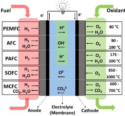
2 The fuel cells can be classified based on the choice of fuels and electrolyte (or ion conductor membranes). At present, five major types of fuel cells are available, as shown in Figure 1.1: proton exchange membrane fuel cells (PEMFCs) including the similar one of direct methanol fuel cell (DMFC), alkaline fuel cells (AFCs), phosphoric acid fuel cells (PAFCs), solid oxide fuel cells (SOFCs), and molten carbonate fuel cells (MCFCs). The former two types are also known as low-temperature fuel cells which are operated at about ca. 80 °C; whereas the latter three types are commonly known as high-temperature fuel cells operated at high temperatures.
Figure 1.1. Overview of five typical fuel cells.
Each kind of fuel cell has its own specific advantages and drawbacks. For example, the operating temperature of SOFCs ranges from 850 °C to 1000 °C, which can be fed by flexible fuels, such as natural gas, oil, gasoline or diesel, etc., have high efficiency and excellent cogeneration [11-13]. Further, the electrolyte for SOFC is solid, so that the electrolyte cannot dry out or leak out as other liquid or membrane ion conductors. However, high temperatures bring tremendous challenges, such as matching materials requirements,
3 mechanical stability, and thermal expansion. Similarly, MCFCs also need to be operated at high temperatures between 600 °C and 700 °C [14]. Previously, PAFC was one of the most mature fuel cells to be used commercially [15, 16]. This type of fuel cell is typically used for stationary power generation between 175 °C and 200 °C, and some PAFCs are used to power large vehicles [17]. However, PAFCs are typically large and heavy leading to lower specific power density than other fuel cells. Further, PAFC is also expensive due to the higher catalyst loading of expensive platinum-group-metal (PGM)-based catalysts than other fuel cells.
AFCs were the first type of fuel cell technology in real-world applications, which generated electricity and water for the U.S. Apollo mission [18]. It is well known that the carbon dioxide (CO2) in the air represents a problem for the wide application of AFCs using
alkaline solution (e.g., potassium hydroxide solution) as the electrolyte. If the fuels/oxidant has a high CO2 content, it is believed that the porous structure of gas diffusion electrodes
(GDEs) will be filled by carbonate gradually and blocked. In fact, even a small amount of CO2 in the air can remarkably affect the cell’s performance. In this regard, the costly and
complicated purification process is necessary for AFCs [19].
The proton exchange membrane fuel cells (PEMFCs), also known as polymer electrolyte membrane fuel cells, have the advantages of high power density, high volume capacity, and low weight, compared to other fuel cells. PEMFCs can be operated at relatively low temperatures (ca. 80 °C), which allows them easy start-up (less warm-up time) and less thermal insulation components on the system. Owing to these advantages, the largest practical use of PEMFCs has been associated with commercial fuel cell vehicles (FCVs) as potential replacements for internal combustion vehicles [20, 21].
1.2.2 Specific Introduction of PEMFCs
PEMFCs were first invented in the early 1960s by GE [22]. At the time, Teflon in the catalyst layer was directly adjacent to the electrolyte. Initially, sulfonated polystyrene membranes were used as electrolytes, but soon the fully fluorinated Nafion® membrane with superior performance and durability was emerging to replace the aforementioned sulfonated polystyrene membranes and is still the most popular membrane in use today. However, at the time the research of PEMFCs did not receive much attention from the
4 federal government (in particular the US Department of Energy (DOE)) and industry. Afterward, Ballard Power Systems Inc. pioneered the research of PEMFCs in the late 1980s and PEMFCs have drawn a world-wide interest. A recent milestone is that Toyota launched its hydrogen fuel cell vehicle of “Mirai” at the Los Angeles Auto Show, on Nov. 2014. This is one of the first mass-market FCVs sold commercially [23]. In 2015, the retail sales of FCVs were 110 vehicles, until 2019, over 6500 FCVs on the road and with expectations for continued growth [24].
1.2.2.1 Main Components and Reaction of PEMFC
The schematic illustration of a PEMFC is demonstrated in Figure 1.2. It consists of a flow field plate, a gas diffusion layer, an anode, a cathode, a proton exchange membrane, and the external circuit. The main part is the membrane electrode assembly (MEA), which sandwiches the anode and the cathode at both sides of the proton exchange membrane where only protons can be conducted. The different electrochemical reactions take place in the catalyst layer at anode and cathode, respectively.
At the anode, H2 is fed as fuels and splits into protons and electrons in the presence of
catalysts. The protons diffuse through the membrane and reach the cathode side. At the cathode side, oxygen molecules react with protons and electrons dragged from anode side by the external circuit.
The chemical reaction at the anode side is hydrogen oxidation reaction (HOR):
Anode: 2H2 → 4H+ + 4e- E = 0.000 V vs. SHE (1)
The chemical reaction at the cathode side is oxygen reduction reaction (ORR):
Cathode: O2 + 4H+ + 4e- → 2H2O E = 1.229 V vs. SHE (2)
The net reaction is:
Net reaction: 2H2 + O2 → 2H2O Ecell = 1.229 V (3)
5 Figure 1.2. Schematic illustration of the components and reaction of a PEMFC.
From the net reaction, we can see that the by-products of PEMFCs are only water and heat. Therefore, PEMFC is the ultimate solution for global warming and environmental pollution issues. In addition, the flow field plates (usually graphite plates) are a pair of supporting parts and current collectors, which have a machined flow field (usually serpentine channel) for supplying the reactants (the fuel and oxygen) to the electrodes.
1.2.2.2 PEMFC Performance
PEMFC performance is indicated by its polarization curve, a plot of voltage-current (E (V)-I (A cm-2)) curve. A typical polarization curve for a PEMFC with three distinct voltage loss regimes is shown in Figure 1.3. An ideally operating fuel cell should provide a constant voltage as long as the reactants and oxidants are supplied. However, the actual cell voltage (Eactual) is always less than the ideal open-circuit voltage (Eideal) due to the irreversible
voltage loss, which is known as the cell overpotential (ηcell). The relationship between the
6 actual= Eideal cell
E
(4) Where
cell=
act
omh
con (5) The three voltage losses of ηact, ηomh, and ηcon represent the activation loss due to thesluggish ORR kinetics, Ohmic loss by the resistance of the cell components and interconnections, and concentration loss at high current densities due to mass transport of reactants within the catalyst layer, respectively.
Figure 1.3. Typical polarization curve of a PEMFC [25].
Activation loss, also known as activation polarization, is caused by the overpotential required to overcome the activation energy of the electrochemical reaction. Therefore, activation losses are the most challenging part. To reduce the activation loss, a better catalyst is needed to reduce the activation barrier, and a lower activation energy barrier is expected to result in a faster reaction rate. A loss in voltage remains due to the slow ORR, because ORR is a complex three-phase interface reaction where gaseous fuel, the catalyst,
7 and electrolyte must be accessible. From the Butler-Volmer equation, the activation loss can be expressed as:
0 = (ln ) act RT i F i (6) where i is the current density and i0 is the reaction exchange current density. T:
thermodynamic temperature (K). F: Faraday constant. R: gas constant. α: charge transfer coefficient. Therefore, the increased exchange current density can reduce the activation loss.
The Ohmic loss is caused by the internal ionic and outer electronic resistances. Internal ionic resistances generally exist inside the membrane (electrolyte) and the catalyst layers. Outer electronic resistances are caused by various components of the fuel cell, such as the electrode substrates, and the two catalyst layers. In the Ohmic polarization region, the relationship between the current density and the cell voltage is almost linear. The concentration loss occurs at a low cell voltage (high current density) region. As the current drawn from the cell is increased, the electrochemical reaction rate in the electrodes increases to meet the current demand. Thus, the consumed reactants also increase to meet the current demand until it reaches a limit that the reactants can no longer be supplied to the active sites because of several limitations, including slow diffusion in the gas phase in the electrode pores, reduced the partial pressure of oxygen in the air, etc. At the practical current densities, slow by-product (i.e., H2O) removal from the active site is a major
contributor to concentration loss.
1.3 Oxygen Reduction Reaction (ORR)
From the aforementioned chemical reaction in PEMFC, the major problem is the sluggish kinetics of ORR at the cathode, since it is ~ 5 orders of magnitude slower than HOR at the anode [26-29]. Therefore, developing a highly efficient catalyst to facilitate the sluggish cathodic ORR is a key issue for PEMFCs.
1.3.1 General Introduction of ORR in PEMFCs
The actual reaction mechanism of ORR is rather complicated, involving different chemical reactions or electron transfer processes and depending on the selectivity of the catalysts
8 and electrolytes. Oxygen molecules can be reduced either in aqueous or non-aqueous electrolytes with different reaction pathways. In aqueous electrolyte, the ORR mainly occurs following two pathways. The one is the two-step 2e- pathway with the formation of hydrogen peroxide (H2O2) as the intermediate product, and the other one is the more
efficient 4e- process to directly reduce O
2 into H2O [30, 31]. In non-aqueous aprotic
electrolytes, aside from the 4e- and 2e- pathways, O2 can also be reduced to superoxide (O2-)
through one-electron transfer [32]. Obviously, the 4e- pathway that reduces O
2 directly into
H2O is highly preferred for PEMFCs.
1.3.2 Class of ORR Catalysts
The ORR is generally catalyzed by various catalysts, such as Pt, to achieve favorable reaction kinetics for practical applications. Among all of the ORR catalysts developed to date, Pt is the best and the most widely used catalyst for both anodic HOR and cathodic ORR [33]. However, the high price and the limited natural reserves of Pt are the major challenges hindering the commercialization of PEMFC [34]. Therefore, significant interest was aroused in developing metal-free or PGM-free catalysts to help either reduce or completely eliminate Pt in PEMFCs.
1.3.2.1 Pt-based Catalysts
ORR is believed sensitive to the surface morphology/shape, particle size and composition of Pt in the Pt-based catalyst [35-37]. Hence, tuning the surface properties, including surface morphology and particle size, etc., is believed to be able to enhance both activity and durability. Further, the high cost and scarcity of Pt have driven great efforts to reduce Pt usage by rational optimizing the intrinsic activity of Pt-involved active sites in Pt-based catalysts. In view of this situation, intense research has been undertaken over the last decade to develop catalysts for PEMFCs that are more active and stable than the currently most prevalent carbon black supported platinum (Pt/C) catalysts. For example, there are several strategies to develop the ultra-low Pt loading catalysts: (1) The first one is dispersing Pt into the atomic level (single-atom catalysts), which can result in ultra-high mass activity [38, 39]; (2) the Second approach is to prepare the well-shaped large Pt-M (mostly Co and Ni) alloy crystallites with distinctive three-dimensional (3D) structures, in which the addition of another metal can alter the availability of active surface sites.
9 However, this approach does not expose all active Pt atoms to the oxidant (i.e., O2 or Air)
[40-42]; (3) Designing controlled architectures, including textured structure, such as core-shell, Pt skin, or Pt monolayer, etc., for Pt-based catalysts.
Figure 1.4. Schematic illustration of the suggested degradation mechanism for supported platinum particles in fuel cells [43].
The aforementioned strategies greatly improve the catalytic activity of Pt-based catalysts. In fact, the stability of the catalysts is another critical factor preventing their practical application in PEMFCs. The fading of Pt-based catalysts occurs via several pathways [43], including the corrosion of the carbon support, Pt detachment and agglomeration, dissolution and Ostwald ripening of the Pt particles, as shown in Figure 1.4. The corrosion of the carbon support occurs because of the oxidation of carbon to CO or CO2 under a
typical cell voltage of fuel cell operating conditions. This carbon corrosion is likely a trigger which results in the weakening of the interaction between the carbon support and
10 the Pt particles, accordingly, further leading to the detachment and agglomeration of the Pt particles. To this end, strategies to enhance the stability of Pt-based catalysts should be carried on: (1) designing new support materials with high conductivity, chemical stability, and surface area to achieving a uniform distribution of Pt or Pt-alloy nanoparticles [44, 45]; (2) Choosing an appropriate catalyst support with high corrosion resistance and with strong interactions with the supported metallic catalyst [46]. Several types of carbon support, including carbon nanofibers, carbon nanotubes, and graphene, etc., have been utilized as supports to improve the stabilities of Pt-based catalysts [47]. It is also recognized that the selection of robust non-carbon support can improve the durability of the catalysts.
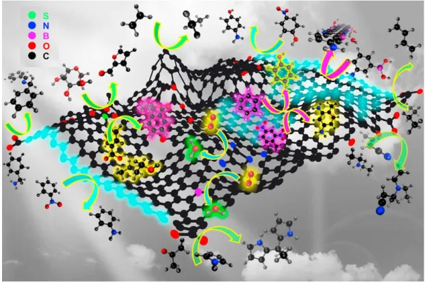
1.3.2.2 Metal-free Catalysts
Metal-free catalysts, also known as heteroatom-doped carbons, are of emerging importance in PEMFCs. Compared with the un-doped analogs, doping of heteroatoms into nanostructured carbon can give rise to enhanced performance in the ORR in terms of both activity and reaction kinetics. The metal-free catalysts typically consist of various heteroatom-doped carbon materials where the heteroatoms are usually non-metallic elements, including B [48, 49], F [50], N [30, 51-55], P [56, 57], S [58, 59], and O [60], etc., or their dual-doping [61-64] and trinary-doping [65, 66] materials. The carbon materials include graphite, graphene, carbon nanotubes (CNTs) and ordered mesoporous carbon. As shown in Figure 1.5, various active sites in metal-free catalysts are considered to be relevant to the ORR. Owing to the low cost, metal-free catalysts are considered as potential alternatives to replace the PGM ORR catalysts of fuel cells. However, the catalytic and decay mechanism of different metal-free catalysts is complicated and still remains unrevealed.
Some researchers believe that the graphitic species play the dominant role in metal-free catalysts [67], while others claim that the heteroatom species is more active and dominant [68-70]. Some authors propose that both graphitic and heteroatom species are active sites [67]. In order to understand the intrinsic activity of the different forms of heteroatom-doped carbon, for example, the N-doped carbon, the tailored synthesis of a specific active site candidate is required. However, this is extremely challenging to implement, since the syntheses usually concurrently yield several types of nitrogen functionalization, such as
11 pyridinic, pyrrolic, or graphitic N, etc. Recently, Dai et al. [70] proposed that the high ORR activity of N-doped carbon catalysts was attributed to the larger electro-negativity of N (electro-negativity of nitrogen: 3.04 vs. carbon: 2.55), and the resulting positive charge density on the adjacent C atoms. However, this explanation is not suitable for other heteroatom-doped carbon materials, such as phosphorus-doped (electro-negativity of phosphorus is 2.19) and B doped (electronegativity of boron is 2.04) carbon materials. The following theoretical DFT simulation has confirmed that breaking the electro-neutrality of carbon materials is a key reason to create charged sites that are favorable for O2 adsorption
and enhance ORR activity, regardless of whether the dopant is electron-rich (e.g., N) or electron-deficient (e.g. P, B) [48]. However, these conclusions are entirely based on theoretical studies. Experimental investigations that can systemically correlate the impact of heteroatom-doping in carbons materials with enhanced ORR activity are rarely reported.
Figure 1.5. Schematic illustration of the possible active sites on graphene and its related synthetic transformations as metal-free catalysts. Black, red, magenta, blue and green balls represent carbon, oxygen, boron, nitrogen, and sulfur atoms, respectively [60].
12 1.3.2.3 TransitionMetal-Nitrogen-Carbon Catalysts (Me/N/C Catalysts)
Among the proposed PGM-free catalysts, transition metal-nitrogen-carbon (Me/N/C) catalysts are considered as one of the most promising ORR catalysts for PEMFC because of the high ORR activity closed to Pt/C catalysts and low price [71-73]. Figure 1.6 summarizes the development of Me/N/C catalysts for ORR. Jasinski et al. published in 1964 that transitions metal porphyrins and phthalocyanines showed an electrochemical activity and could be used as cathode material in fuel cells [74]. It is unfortunate that other researchers found this type of catalyst was not stable in the acidic environment [75]. In 1976, Jahnke et al. demonstrated that the activity and stability of the transition metal macrocycles were improved by heat treatment under an inert atmosphere [76]. Since that time, the synthesis method of Me/N/C catalyst is focused on pyrolyzing metal-N4 (MeN4)
macrocycles supported on high surface area carbons [77]. Another great breakthrough was made by Yeager's group in 1989: Me/N/C catalysts were synthesized by simple organic or inorganic precursors (polyacrylonitrile/Co(II) or Fe(II) acetate) which were attached on a high surface area carbons [78]. Following so, Me/N/C catalyst can be obtained by pyrolyzing metal salt or metal complexes and nitrogen precursor with carbon. This approach allows us to design and synthesize Me/N/C catalyst with more flexible precursors.
13 Figure 1.6. Development of Me/N/C catalysts for ORR.
However, Me/N/C catalysts could not be used as alternatives to replace the Pt-based catalysts due to the unsatisfied ORR performance. In 2005, a benchmark between PGM-free catalysts and PGM catalysts were proposed. If the PGM-PGM-free catalysts have activity lower than 1/10 (A/cm3) of Pt/C catalysts, they could never be used for FCVs applications
due to the limited physical spaces when designing an automobile [79]. Therefore, the intense effort has been made on minimizing the gap between Me/N/C catalysts and Pt/C. In 2009, the Dodelet group at INRS reported a ground-breaking achievement in the ORR activity [80]: the 99 A cm-3 @ 0.8 ViR-free of their reported Fe/N/C catalysts are much closer
to the 2010 DOE target of 130 A cm-3 for ORR on PGM-free catalyst. In 2011, the Dodelet group further improved the Fe/N/C catalyst by using a metal-organic framework (MOF), Zn zeolitic imidazolate (ZIF-8), as the host for Fe and N precursors. The catalyst has a peak power density of 0.91 W cm-2 and a volumetric current density of 230 A cm-3 @ 0.8 V iR-free, which is closer to the 2015 DOE target of 300 A cm-3. Both the reported activities were
the highest for PGM-free catalysts in PEMFCs at the time. The latter performance is comparable with the state-of-the-art Pt/C cathode with a loading of 0.3 mgPt cm-2 [81].
However, at high current density region, the cell performance is limited by mass transport across the cathode layer (In order to achieve the maximum current density, the cathode catalyst loading are usually at 3-4 mg cm-2 with a layer thickness of 100 μm [82]), and the catalyst suffers from 40% decay in the stability test at constant voltage of 0.6 V within 15 hours. Meanwhile, Zelenay et al. developed a FeCo/N/C catalyst with excellent 4e -selectivity (H2O2 yield < 1.0%) and long-term stability at a constant voltage of 0.4 V [83].
However, the two stability results are incomparable due to the different test protocols (e.g., 0.6 V vs. 0.4 V).
14 Figure 1.7. Experimental evidence of FeN4 moieties: (a) Single-atom resolution
aberration-corrected scanning transmission electron microscopy, (b) electron energy-loss spectroscopy, and (c) extended X-ray absorption fine structure [84].
With such achievements, numerous challenges still remain before PGM-free catalysts become viable for PEMFCs, of which the catalyst instability seems to be the greatest. There has been a growing consensus that the active sites in Me/N/C catalyst can be generally summarized as MeNx (most as Me-N4), CNx, Fe3C, Fe@N/C, defects, edges, etc. [85]. The
most active sites for ORR are commonly viewed as Me-Nx bounded to the carbon matrix, which is supported by a wealth of experimental data [86-90]. Figure 1.7 shows the atomic-level microscopic and spectroscopic evidence for MeN4 from aberration-corrected
scanning transmission electron microscopy [86, 91]. Due to the complex nature and diversity of active sites, the decay mechanism for Me/N/C catalyst are still under debate and facing considerable difficulties to be completely revealed. To date, four decay mechanisms have been proposed for the PGM-free catalysts in the PEMFCs [84]: (1) micropore flooding; (2) protonation of active sites or N moieties next to the active sites; (3) demetalation; (4) carbon oxidation. Possibly all these mechanisms can be responsible for the fading of PGM-free catalysts to some extent, but more research and comparable experimental data are needed.
To sum up, since Jasinski first reported PGM-free catalysts for ORR in 1964, great efforts have been provided and encouraging progress has been obtained to develop efficient Me/N/C catalysts. However, the following challenges remain: (1) The long-term instability of the Me/N/C catalyst; (2) the controversial decay mechanism; (3) unreached unified and benchmarked test protocols; (4) the slow mass transport of thick Me/N/C catalyst layer. To address the above challenges and push the PGM-free catalyst forward, a better (in situ) characterization, a catalyst modification in the MEA level and a systematic test protocol study are the prerequisites.
1.4 Thesis Objectives
As discussed above, this thesis is aiming at addressing the inescapable problems based on our highly active Fe/N/C catalyst. The topic of this thesis is reasonable as “A comprehensive study on non-precious metal catalysts for Proton Exchange Membrane Fuel
15 Cells (PEMFCs)”. To address several key points in PGM-free catalyst study (e.g., slow mass transport and diverse test protocols, etc.), specific Objectives are listed below: Objective I: The optimized catalyst layer with high Fe/N/C loading (3-4 mgFe/N/C cm-2) has
a thickness of up to 100 μm, leading to a severe mass transport loss at the low cell voltage. Thus, the fabrication of MEA with high catalyst loading and fast mass transport is great challenging. To address this issue, the porosity and wettability of our highly active Fe/N/C catalyst are expected to be adjusted by SiO2 nanoparticle network structures. Through
adjusting porosity and wettability, the catalyst layer should have more transport channels for oxidants.
Objective II: The reported stability behavior and test protocols of Fe/N/C catalysts are varied from lab to lab, which likely sets a big barrier to compare the results and further understand the fading mechanism. In order to clear the hurdles for the stability and decay mechanism research, the stability behaviors of our highly active Fe/N/C catalyst will be investigated under different protocols (e.g., at different constant voltages or currents, etc.). The optimized test protocol and benchmark will be obtained.
Objective III: The stability curves of our Fe/N/C catalyst can be fitted by the summation of two exponential decays: (1) the fast exponential decay which results from the specific demetalation of FeNx sites located in the micropores of the catalyst; and (2) the slow decay involving the action of H2O2 and its derived aggressive species with FeNx catalytic sites
located everywhere in the catalyst. So far, there is still challenging to solve the stability issue from root-cause. For addressing the stability issue, a novel hybrid GDE engineer between Fe/N/C and ultra-low loading Pt/C catalysts is proposed to increase the stability of Fe/N/C catalyst. The fast decay of Fe/N/C will be compensated by the activation process of Pt/C catalyst
1.5 Outline of the Thesis
This thesis consists of six chapters, including one introductory chapter, one experimental chapter, three articles, and one final chapter. Specifically, they are arranged as follows: Chapter 1: This thesis begins with a general introduction of PEMFCs and an overview of varies of catalysts for the PEMFC cathode in chapter 1. Five types fuel cells are
16 summarized with their respective advantages and shortcomings. Recent developments of three main types of catalysts for the ORR are presented in detail as (i) PGM catalysts; (ii) Metal-free catalysts; (iii) Me/N/C catalysts. Besides, the thesis objectives and the thesis organization of this study are also clearly stated.
Chapter 2: This part describes the details of materials synthesis, several physical and electrochemical analytical techniques, which were used to study and characterize the samples in this thesis.
Chapter 3: Enhancing cathode mass transport. This part (SiO2-Fe/N/C catalyst with
enhanced mass transport in PEM Fuel Cells) reports a facile powerful ball-milling method to synthesize SiO2 mixed Fe/N/C catalyst. This novel SiO2-Fe/N/C catalyst shows
much-improved mass transport properties.
Chapter 4: Investigation on the decay mechanism of Fe/N/C catalyst under different stability test protocols. (Stability study for non-platinum group metal catalyst in PEMFCs: potentiostatic or galvanostatic protocol?). Based on our high active Fe/N/C catalyst, this part demonstrates the dependent of catalyst stability on potentiostatic and galvanostatic test protocols, a stability test benchmark of potentiostatic test @ 0.4-0.6 V is highly recommended.
Chapter 5: Enhancing the stability and activity of PGM-free catalyst with the assistance of Pt/C catalyst. (PGM-free Fe/N/C and ultra-low loading Pt/C hybrid cathode catalysts with enhanced stability and activity in PEM Fuel Cells). This part explores a new GDE fabricating strategy by combining the Pt/C catalyst layer (with ultra-low Pt loading) and Fe/N/C catalyst layer to increase the stability and shorten the activation time. This novel catalyst layer was prepared by coating a thin Pt/C layer on the surface of Fe/N/C catalyst layer. Electrochemical properties, such as stability and activity, were compared with the pure Fe/N/C and Pt/C GDEs. The results show that the stability of the hybrid GDEs is increased by the synergistic effect between Fe/N/C and Pt/C catalyst layer. This work provides a new and effective strategy to bypass the hinder of the instability of Fe/N/C and the limited natural reserves of Pt for the industrialization for PEMFCs.
Chapter 6: This part summarizes the results and main conclusions of the thesis work. In addition, some perspectives and outlook are provided for future work.
17 In this thesis, most of the work was completed by Xiaohua Yang under the guidance of Prof. Shuhui Sun; Dr. Gaixia Zhang gave important suggestions and guidance on the data analysis. Dr. Lei Du helps for the revision of several articles and thesis. Dr. Yucheng Wang helps with the wettability parts of the experiment design of Chapter 3. The collaborators from Ballard Power Systems contributed to the formation of the final version with discussion. Dr. Qiliang Wei shows the operation of the instruments in this lab when Xiaohua Yang is a first-year Ph.D. student. Xiaohua Yang, Dr. Gaixia Zhang and Prof. Shuhui Sun conceived the project and designed the experiments. All authors discussed the results and gave comments on the manuscripts.
References
[1] S. Chu, Y. Cui, N. Liu, The path towards sustainable energy, Nat. Mater., 16 (2017) 16-22.
[2] M. Lefevre, J.P. Dodelet, Recent Advances in Non-precious Metal Electrocatalysts for Oxygen Reduction in PEM Fuel Cells, ECS Trans., 45 (2012) 35-44.
[3] M.Z. Jacobson, M.A. Delucchi, Z.A.F. Bauer, S.C. Goodman, W.E. Chapman, M.A. Cameron, C. Bozonnat, L. Chobadi, H.A. Clonts, P. Enevoldsen, 100% clean and renewable wind, water, and sunlight all-sector energy roadmaps for 139 countries of the world, Joule, 1 (2017) 108-121.
[4] A. Sartbaeva, V. Kuznetsov, S. Wells, P. Edwards, Hydrogen nexus in a sustainable energy future, Energy Environ. Sci., 1 (2008) 79-85.
[5] M.W. Ellis, M.R. Von Spakovsky, D.J. Nelson, Fuel cell systems: efficient, flexible energy conversion for the 21st century, Proc. IEEE, 89 (2001) 1808-1818.
[6] J.-H. Wee, K.-Y. Lee, S.H. Kim, Sodium borohydride as the hydrogen supplier for proton exchange membrane fuel cell systems, Fuel Process. Technol., 87 (2006) 811-819. [7] J. St-Pierre, D.P. Wilkinson, Fuel cells: a new, efficient and cleaner power source, American Institute of Chemical Engineers. AIChE J., 47 (2001) 1482-1486.
18 [9] A.B. Stambouli, E. Traversa, Fuel cells, an alternative to standard sources of energy, Renew. Sust. Energy Rev., 6 (2002) 295-304.
[10] A.J. Appleby, E.B. Yeager, Solid polymer electrolyte fuel cells (SPEFCs), Energy, 11 (1986) 137-152.
[11] E. Ivers-Tiffée, A. Weber, D. Herbstritt, Materials and technologies for SOFC-components, J. Eur. Ceram. Soc., 21 (2001) 1805-1811.
[12] J. Huijsmans, F. Van Berkel, G. Christie, Intermediate temperature SOFC–a promise for the 21st century, J. Power Sources, 71 (1998) 107-110.
[13] S. Badwal, K. Foger, Solid oxide electrolyte fuel cell review, Ceram. Int., 22 (1996) 257-265.
[14] E. Antolini, The stability of molten carbonate fuel cell electrodes: a review of recent improvements, Appl. energy, 88 (2011) 4274-4293.
[15] A. Kirubakaran, S. Jain, R. Nema, A review on fuel cell technologies and power electronic interface, Renew. Sust. Energy Rev., 13 (2009) 2430-2440.
[16] T. Fuller, M. Perry, C. Reiser, Applying the lessons learned from PAFC to PEM fuel cells, ECS Trans., 1 (2006) 337-344.
[17] R. Anahara, A perspective on PAFC commercialization by Fuji Electric, J. Power Sources, 37 (1992) 119-131.
[18] M. Warshay, P.R. Prokopius, The fuel cell in space: yesterday, today and tomorrow, NASA Technical Report (1989).
[19] C. Bernay, M. Marchand, M. Cassir, Prospects of different fuel cell technologies for vehicle applications, J. Power Sources, 108 (2002) 139-152.
[20] S. Nagamatsu, S. Takao, G. Samjeske, K. Nagasawa, O. Sekizawa, T. Kaneko, K. Higashi, T. Uruga, S. Gayen, S. Velaga, M.K. Saniyal, Y. Iwasawa, Structural and Electronic Transformations of Pt/C, Pd@Pt(1 ML)/C and Pd@Pt(2 ML)/C Cathode Catalysts in Polymer Electrolyte Fuel Cells during Potential-step Operating Processes Characterized by In-situ Time-resolved XAFS, Surf. Sci., 648 (2016) 100-113.
19 [21] T. Yoshida, K. Kojima, Toyota MIRAI Fuel Cell Vehicle and Progress Toward a Future Hydrogen Society, Electrochem. Soc. Interface, 24 (2015) 45-49.
[22] P. Costamagna, S. Srinivasan, Quantum jumps in the PEMFC science and technology from the 1960s to the year 2000: Part II. Engineering, technology development and application aspects, J. Power Sources, 102 (2001) 253-269.
[23] M. Shao, Q. Chang, J.-P. Dodelet, R. Chenitz, Recent advances in electrocatalysts for oxygen reduction reaction, Chem. Rev., 116 (2016) 3594-3657.
[24] S.T. Thompson, D. Papageorgopoulos, Platinum group metal-free catalysts boost cost competitiveness of fuel cell vehicles, Nat. Catal., 2 (2019) 558.
[25] T. Agaesse, Simulations of one and two-phase flows in porous microstructures, from tomographic images of gas diffusion layers of proton exchange membrane fuel cells, (2016).
[26] W. Xia, A. Mahmood, Z. Liang, R. Zou, S. Guo, Earth‐Abundant Nanomaterials for Oxygen Reduction, Angew. Chem. Int. Ed., 55 (2016) 2650-2676.
[27] R.M. Darling, J.P. Meyers, Kinetic model of platinum dissolution in PEMFCs, J. Electrochem. Soc., 150 (2003) A1523-A1527.
[28] F. Jaouen, J. Herranz, M. Lefevre, J.P. Dodelet, U.I. Kramm, I. Herrmann, P. Bogdanoff, J. Maruyama, T. Nagaoka, A. Garsuch, J.R. Dahn, T. Olson, S. Pylypenko, P. Atanassov, E.A. Ustinov, Cross-laboratory experimental study of non-noble-metal electrocatalysts for the oxygen reduction reaction, ACS Appl. Mater. Inter., 1 (2009) 1623-1639.
[29] S. Sun, G. Zhang, D. Geng, Y. Chen, R. Li, M. Cai, X. Sun, A highly durable platinum nanocatalyst for proton exchange membrane fuel cells: multiarmed starlike nanowire single crystal, Angew. Chem. Int. Ed. Engl., 50 (2011) 422-426.
[30] Q. Wei, X. Tong, G. Zhang, J. Qiao, Q. Gong, S. Sun, Nitrogen-Doped Carbon Nanotube and Graphene Materials for Oxygen Reduction Reactions, Catal., 5 (2015) 1574-1602.
20 [31] W.R.P. Barros, Q. Wei, G. Zhang, S. Sun, M.R.V. Lanza, A.C. Tavares, Oxygen reduction to hydrogen peroxide on Fe3O4 nanoparticles supported on Printex carbon and Graphene, Electrochim. Acta, 162 (2015) 263-270.
[32] C. Song, J. Zhang, Electrocatalytic oxygen reduction reaction, PEM fuel cell electrocatalysts and catalyst layers, Springer2008, pp. 89-134.
[33] Y. Nie, L. Li, Z. Wei, Recent advancements in Pt and Pt-free catalysts for oxygen reduction reaction, Chem. Soc. Rev., 44 (2015) 2168-2201.
[34] Z. Zhang, X. Gao, M. Dou, J. Ji, F. Wang, Biomass Derived N‐Doped Porous Carbon Supported Single Fe Atoms as Superior Electrocatalysts for Oxygen Reduction, Small, 13 (2017) 1604290.
[35] P. Strasser, S. Koh, T. Anniyev, J. Greeley, K. More, C. Yu, Z. Liu, S. Kaya, D. Nordlund, H. Ogasawara, Lattice-strain control of the activity in dealloyed core–shell fuel cell catalysts, Nat. Chem., 2 (2010) 454.
[36] J.R. Kitchin, J.K. Nørskov, M.A. Barteau, J.G. Chen, Modification of the surface electronic and chemical properties of Pt (111) by subsurface 3d transition metals, J. Chem. Phys., 120 (2004) 10240-10246.
[37] V.R. Stamenkovic, B.S. Mun, M. Arenz, K.J.J. Mayrhofer, C.A. Lucas, G. Wang, P.N. Ross, N.M. Markovic, Trends in electrocatalysis on extended and nanoscale Pt-bimetallic alloy surfaces, Nat. Mater., 6 (2007) 241-247.
[38] R. Makharia, S. Kocha, P. Yu, M.A. Sweikart, W. Gu, F. Wagner, H.A. Gasteiger, Durable PEM fuel cell electrode materials: Requirements and benchmarking methodologies, Ecs Trans., 1 (2006) 3-18.
[39] L. Chong, J. Wen, J. Kubal, F.G. Sen, J. Zou, J. Greeley, M. Chan, H. Barkholtz, W. Ding, D.-J. Liu, Ultralow-loading platinum-cobalt fuel cell catalysts derived from imidazolate frameworks, Science, 362 (2018) 1276-1281.
[40] L. Bu, N. Zhang, S. Guo, X. Zhang, J. Li, J. Yao, T. Wu, G. Lu, J.-Y. Ma, D. Su, Biaxially strained PtPb/Pt core/shell nanoplate boosts oxygen reduction catalysis, Science, 354 (2016) 1410-1414.
![Figure 1.3. Typical polarization curve of a PEMFC [25].](https://thumb-eu.123doks.com/thumbv2/123doknet/5004999.124746/27.918.170.747.358.812/figure-typical-polarization-curve-pemfc.webp)
![Figure 1.4. Schematic illustration of the suggested degradation mechanism for supported platinum particles in fuel cells [43]](https://thumb-eu.123doks.com/thumbv2/123doknet/5004999.124746/30.918.140.769.201.744/schematic-illustration-suggested-degradation-mechanism-supported-platinum-particles.webp)

![Figure 2.2 Basic principle of a TEM [2].](https://thumb-eu.123doks.com/thumbv2/123doknet/5004999.124746/50.918.281.625.513.946/figure-basic-principle-tem.webp)

![Figure 2.5 Illustration of the Bragg equation in XRD measurements [7].](https://thumb-eu.123doks.com/thumbv2/123doknet/5004999.124746/55.918.193.717.441.671/figure-illustration-bragg-equation-xrd-measurements.webp)