HAL Id: hal-00502365
https://hal.archives-ouvertes.fr/hal-00502365
Submitted on 13 Jul 2010
HAL is a multi-disciplinary open access
archive for the deposit and dissemination of
sci-entific research documents, whether they are
pub-lished or not. The documents may come from
teaching and research institutions in France or
abroad, or from public or private research centers.
L’archive ouverte pluridisciplinaire HAL, est
destinée au dépôt et à la diffusion de documents
scientifiques de niveau recherche, publiés ou non,
émanant des établissements d’enseignement et de
recherche français ou étrangers, des laboratoires
publics ou privés.
Ultra Wide Band over fibre transparent architecture for
High Bit-rate Home Networks
Quoc Thai Nguyen, Anna Pizzinat, Benoit Charbonnier, Sylvain Meyer,
Philippe Guignard
To cite this version:
Quoc Thai Nguyen, Anna Pizzinat, Benoit Charbonnier, Sylvain Meyer, Philippe Guignard. Ultra
Wide Band over fibre transparent architecture for High Bit-rate Home Networks. ” Advanced optical
communications systems : from short range to long haul networks ” 2007 e-PhotonONe+ Summer
School, Jul 2007, Brest, France. pp.1-4. �hal-00502365�
Ultra Wide Band over fibre transparent architecture for High
Bit-rate Home Networks
Q. T. Nguyen, A. Pizzinat, B. Charbonnier, S. Meyer, P. Guignard
France Telecom Research & Development Division, 2 Avenue Pierre Marzin 22307 Lannion, France Email: quocthai.nguyen@orange-ftgroup.com
A
BSTRACTWe numerically and experimentally demonstrate the feasibility of an Ultra Wide Band (UWB) over fiber
transparent architecture based on laser direct
modulation and using single mode fiber (SMF) for high bit rate home networks.
1.
I
NTRODUCTIONToday two phenomena are driving the increase of the bit rate needed in a home network. The first one is the multiplication of connected devices (i.e. computers, media centers, media renderers etc…) and of services available to the end user (i.e. domestic storage area network, video-phony and video conferencing, TVoIP, ToIP, etc…). The second phenomenon is the evolution of fiber to the home. As a consequence, a well connected home will need an internal network working at speeds of 1 Gbit/s by 2010 [1]. Whereas such a target might not be attained by current wired solutions, the large bandwidth of optical fibers makes of them the only solution able to guarantee a long life to the network infrastructure and justify the expense for the installation of a new cable. Moreover, using an optical fiber as a home backbone may be seen as the natural prolongation of the optical access.
Additionally, it has to be noted that users have developed a strong preference for wireless connectivity and will require that future systems evolve to higher data rates while remaining wireless. A solution to this requirement can be found in Ultra Wide Band (UWB) technologiy [2], [3]. UWB radio systems operate in the frequency range from 3.1 to 10.6 GHz and offer a wireless connectivity up to 1 Gbit/s, but, as a result are limited in coverage to a few meters (< 10 m).
In this paper we propose to couple radio UWB systems to an optical fibre backbone as shown in figure 1 so to extend the coverage to a few hundred meters, i.e. the typical dimension of an in-building network. The radio home networks will then become a multicellular network with the additional potential of transparently distributing, in parallel with the UWB signal mentioned above, other conventional baseband data signals (GbE etc..) or other radio signals throughout the house such as mobile signals (UMTS, 3G etc…), or different standards of WiFi (e.g. IEEE802.11n) [4], [5]. The
important point is the mutualisation of the infrastructure that radio over fiber (RoF) achieves.
FTTH DL >>100Mb/s UL >>100Mb/s NAS 1GbE 1GbE + UWB HDTV DVR HiFi 3G Phone Office Lounge Bedroom Gateway House control Optical infrastructure 1Gb UWB 1Gb UWB LDR UWB 1Gb UWB
Figure 1: Very High Data Rate Home Area Network supported by an optical infrastructure
In particular, we use the optical fibre as a tunnel that allows enlarging an UWB cell in a completely transparent way, by means of a passive multipoint to multipoint (MP2MP) architecture based on an NxN splitter. This architecture is advantageous because it is equivalent to having all the users in the same room. RoF has been demonstrated over many types of optical fiber even on legacy multimode fibers [6], but an analysis and experimentation of a complete system keeping into account at the same time for the radio and optical transmission is still lacking. In the following sections we will present the MP2MP architecture. Then, we will introduce the system budget link calculation and compare it with numerical simulations. Finally, we will present the experimental results and come to conclusions.
2.
MP2MP
A
RCHITECTUREThe proposed architecture is shown in figure 2 and described in detail in [7]. The key point is the NxN splitter thanks to which a signal injected at a network input reaches all network outputs. An important choice concerns the fibre type. Indeed, for cost reasons the use of multi-mode fibre and VCSEL may be preferred, but the perennity of such a home backbone has also an important weight. Thus, we study numerically and experimentally the feasibility of the proposed system in the case of single-mode fibres (SMF). Considering now only the RoF link between two end users, the link to be dimensioned takes the form shown in figure 3.
Fig. 2: Hybrid Wireless-Optical MP2MP Architecture
Fig. 3: System setup
The UWB signal directly modulates a laser, then, after propagation on the fibre the electrical signal at the output of the photodiode directly feeds the UWB antenna. Moreover, it has to be noted that the system is independent of the used radio format as far as it respects the laser and PIN frequency bands. The link shown in figure 2 has been evaluated by means of analytical link budget calculations and extensive simulations using Matlab and VPI Transmission Maker. The first three UWB bands have been considered. The power at the output of the transmitting antenna is fixed to -14 dBm for an OFDM band of 528 MHz (-41.3dBm/MHz). Amplification is needed before the laser so to partially compensate the free space losses. The 16x16 splitter is considered so to simulate 16 access points.
3.
S
IMULATIONR
ESULTSFist of all, the system shown in figure 3 has been analytically characterised in terms of link budget. The gain, noise factor and signal to noise ratio (SNR) at the UWB receiver have been calculated for the global link including radio and optical propagation [8]. The received bit error rate (BER) is also estimated from the SNR. For the radio channel only free space losses have been taken into account as a first order approximation. In spite of being valid only for a linear system, the link budget calculation of fundamental importance for the system dimensioning, i.e.: the ratio of the NxN coupler and the amplification stage.
For a targeted BER of 10-5 (that corresponds to error
free propagation with coding), we have found that the dimension of the system can reach 16x16 for a propagation distance on each air link up to 10m.
Besides the system dimensioning, the amplification stage (fig. 3) is also a critical point of the system. This amplification stage is composed of a high gain low noise amplifier (LNA), followed by an electrical variable attenuator and a high power amplifier (HPA). The role of the LNA is to compensate the attenuation of the UWB signal due to the propagation in the first air link. The variable attenuator is used to keep constant the RF power at the laser input independently of the propagation distance on the first air link. Finally, the HPA is used to increase the RF power of the UWB signal at the input of the RoF link, in order to compensate the very weak RF gain of the RoF link (about -32.5dB). At the output of the RoF link, an electrical attenuator is used to ensure that the transmitting power of the Tx2 antenna respects the regulation. The parameters for all the system components are shown in Table 1.
Other two parameters that can be tuned are the laser input RF power and polarisation current. Their values must be chosen so to avoid laser clipping and third order intermodulation effects. VPI Transmission Maker simulations and the characterization of a RoF link showed that the RF power injected into the RoF link can be up to 18dBm without strong degradation due to the clipping effect of the laser. Therefore, the RF power injected into the RoF link is adjusted to 15dBm. Fig. 4 and 5 show the evolutions of the SNR and BER of the UWB signal transmitted through the optical - wireless hybrid system (fig. 3) as a function of the propagation distance on the two air links.
ηEO 0.08W/A @ IBias = 80mA
Zin 50 Ω
RIN Extracted from real DFB
laser (-140 dBc/Hz) Imax 150 mA IBias 80mA DFB Laser IThreshold 10mA Length < 500m Attenuation 0.2 dB/km SMF D 16 ps/nm/km ηOE 0.95 A/W Zout 50 Ω ZTIA 500 Ω PIN Photodiode NEP 11.54 pA/Hz1/2 Splitter Ratio 16x16
Optical Loss 15dB (including 12dB optical loss of 16x16
splitter) Antenna GTx/Rx 7dB G 56dB NF 0.6dB Pout@1dBComp 10dBm LNA Freq. Range 2.6GHz – 5.2GHz
Var. Attenuator Att. Range 0dB – 30dB
G 35dB
NF 5.7dB
Pout@1dBComp 26dBm
HPA
Freq. Range 0.5GHz – 8.0GHz
Fix Attenuator Attenuation 4dB
Pre-Amplifier
at Reception NF 2.5dB
Fig. 3: SNR of the first UWB sub-band (3.432GHz) at the system output as a function of the propagation
distance on the two air links.
Fig. 4: BER of the first UWB sub-band as a function of the propagation distance on the two air links. The system behavior has been then numerically simulated in Matlab and VPI in order to analyze also nonlinear effects in the electro-optic conversion. For these simulations, we generate a pseudo random bit sequence at 640Mbps for each OFDM sub-band, we apply QPSK modulation and obtain the OFDM signal according to [3]. Afterwards, we extract the UWB baseband signal in base-band and load it into VPI. There, the UWB signal is transposed in frequency to create the OFDM sub-band (at 3.432GHz, 3.960GHz and 4.488GHz). Then, the UWB signal is transmitted through the system (described in fig.3) implemented in VPI. The propagation in each air link is simulated by a filter which has the frequency response corresponding to free space propagation. At the system output, the UWB signal is brought back to base-band and loaded into Matlab for OFDM demodulation and performance evaluation. Figures 5 and 6 show the temporal and spectral behavior of the UWB signal and the QPSK transmitted and received constellations, respectively.
Fig. 5: Temporal and spectral representations of the ideal UWB signal (including thermal noise only) in the
first OFDM sub-band (3.432GHz)
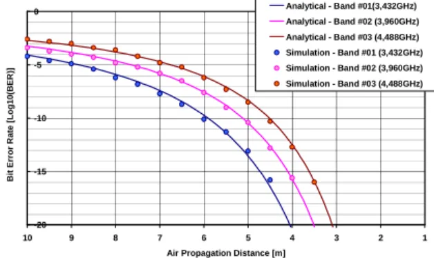
Fig. 6: Constellation diagram of DATA sub-carriers: ideal (left) and after transmission (right) Figure 7 shows the BER as a function of the air propagation distance (supposing equal distances on the two links). A good agreement between analytical calculation and simulation results can be observed.
-20 -15 -10 -5 0 1 2 3 4 5 6 7 8 9 10
Air Propagation Distance [m]
B it E rr o r R a te [ L o g 1 0 (B E R )] Analytical - Band #01(3,432GHz) Analytical - Band #02 (3,960GHz) Analytical - Band #03 (4,488GHz) Simulation - Band #01 (3,432GHz) Simulation - Band #02 (3,960GHz) Simulation - Band #03 (4,488GHz)
Fig. 7: Bit error rate as a function of the transmission distance on the two air links.
From this simulation result, we can conclude that the propagation distance on each air link can reach up to
7m for a targeted BER of 10-5.
4.
E
XPERIMENTALR
ESULTSThe feasibility of the system shown in fig. 3 has been then experimentally demonstrated. For the moment, we have only tested the transmission of the UWB signal on the optical fibre that is named optical tunnel to underline its transparency. We have introduced RF attenuation in order to simulate free space losses of the first air link. Figure 8 shows the system setup and its composition. It has to be noted that this configuration
corresponds to the transmission between a user and the gateway in the architecture of figure 2.
Fig. 8: Configuration of the optical tunnel in the MP2MP architecture
The principle of the experimental characterization is the same as that applied in the case of the numerical simulation. The UWB signal is loaded into an arbitrary waveform generator (AWG) through a LabVIEW interface (figure 9). After an attenuation stage the signal is sent to the optical tunnel for testing. At the tunnel output, the UWB signal is read by the real time oscilloscope and loaded into the computer. Finally, the UWB signal is demodulated and evaluated by Mablab.
Fig. 9: Principle of the experimental test bench
The optical tunnel has the same parameters given in table 1. To evaluate the performance of the optical tunnel in the same operating condition as in the hybrid optical – wireless system shown in the figure 3, the RF power of the UWB signal at the tunnel input has to be very weak due to the attenuation of the propagation on the first air link. Therefore, the performance of the tunnel is evaluated for an input RF power ranging from -80dBm to -50dBm. The BER of the UWB signal transmitted through the tunnel is reported in the fig. 10, which includes as well the propagation distance on the first air link corresponding to the input RF power. From this experimental result, we can conclude that the quality of UWB signal at the output of the optical
tunnel is always maintained (BER < 10-12) for the
propagation distance lower than 10m on the first air link. If the system does not include the second air link (communication between the end user and the gateway in fig. 2 for example), the range of the only air link can
reach up to 20m for a targeted BER of 10-5.
-20 -15 -10 -5 0 -80 -77 -74 -71 -68 -65 -62 -59 -56 -53 -50 RF Power at the tunnel input [dBm]
B it E rr o r R a te [ L O G 1 0 (B E R )] 0 10 20 30 40 P ro p a g a ti o n d is ta n c e o n t h e f ir s t a ir l in k [ m ] BER - Band #01 (3.432GHz) BER - Band #02 (3.960GHz) BER - Band #03 (4.488GHz) Propagation Distance - Band #01 (3.432GHz) Propagation Distance - Band #02 (3.960GHz) Propagation Distance - Band #03 (4.488GHz)
-Fig. 10: BER of UWB signal transmitted through the optical tunnel as a function of input RF power
5.
C
ONCLUSIONSWe have demonstrated the feasibility of using a hybrid optical – RF wireless system based on single mode
fibre to transmit UWB radio signals corresponding to
first 3 OFDM sub-bands of 528 MHz in 3.1GHz – 4.7GHz frequency range, each carrying 640 Mbps. Such results prove the possibility of deploying very
high bit-rate,UWB based multi-cellular home wireless
networks using multipoint-to-multipoint transparent architecture.
A
CKNOWLEDGEMENTSThis work has been done in the frame of the national project RNRT/BILBAO and of the ePhotonONE+ VDH Network of Excellence.
R
EFERENCES[1] M. Bellec, "Home Broadband Home Area Network", Keynote 3, Tuesday 3rd April, European Wireless 2007
[2] FCC, "Rev. Part 15 of the Commission's Rules Regarding UWB Transmission System", ET Docket 98-153, FCC-2-48, 2002. [3] Standard ECMA-368, Geneva, 1st ed. Dec.2005.
[4] http://www.ieee802.org/15/pub/TG3c.html
[5] Michael J. Crisp et al, "Demonstration of a Radio over Fibre Distributed Antenna Network for Combined In-building WLAN and 3G Coverage", OFC2007, JThA81
[6] Anna Pizzinat et al, "1.92Gbit/s MB-OFDM Ultra Wide Band Radio Transmission over Low Bandwidth Multimode Fiber", OFC2007, OThM6.
[7] P. Guignard et al., "Home network based on CWDM broadcast and select technology", accepted for the presentation at ECOC 2007, Berlin.
[8] C. Carlsson et al, "RF transmission over Multimode Fibers using VCSELs-comparing standard and highbandwidth multimode fibers", IEEE J. Lightwave Technol., pp. 1694-1700, 2004.