Drone Relays for Battery-Free Networks
The MIT Faculty has made this article openly available.
Please share
how this access benefits you. Your story matters.
Citation
Ma, Yunfei, Nicholas Selby, and Fadel Adib. "Drone Relays for
Battery-Free Networks." Proceedings of the Conference of the ACM
Special Interest Group on Data Communication, August 2017, Los
Angeles, CA, USA, Association for Computing Machinery, 2017
As Published
http://dx.doi.org/10.1145/3098822.3098847
Publisher
ACM
Version
Author's final manuscript
Citable link
https://hdl.handle.net/1721.1/125328
Terms of Use
Creative Commons Attribution-Noncommercial-Share Alike
Yunfei Ma, Nicholas Selby, Fadel Adib
Massachusetts Institute of Technology{yunfeima,nselby,fadel}@mit.edu
ABSTRACT
Battery-free sensors, such as RFIDs, are annually attached to billions of items including pharmaceutical drugs, clothes, and manufacturing parts. The fundamental challenge with battery-free sensors is that they are only reliable at short distances of tens of centimeters to few meters. As a result, today’s systems for communicating with and localizing battery-free sensors are crippled by the limited range.
To overcome this challenge, this paper presents RFly, a system that leverages drones as relays for battery-free networks. RFly de-livers two key innovations. It introduces the first full-duplex relay for battery-free networks. The relay can seamlessly integrate with a deployed RFID infrastructure, and it preserves phase and timing characteristics of the forwarded packets. RFly also develops the first RF-localization algorithm that can operate through a mobile relay.
We built a hardware prototype of RFly’s relay into a custom PCB circuit and mounted it on a Parrot Bebop drone. Our experimental evaluation demonstrates that RFly enables communication with com-mercial RFIDs at over 50 m. Moreover, its through-relay localization algorithm has a median accuracy of 19 centimeters. These results demonstrate that RFly provides powerful primitives for communica-tion and localizacommunica-tion in battery-free networks.
CCS CONCEPTS
• Networks → Cyber-physical networks; Mobile networks; Sensor networks;
KEYWORDS
Drones, RFID, Relay, Full-Duplex, Localization, Battery-free, SAR
ACM Reference format:
Yunfei Ma, Nicholas Selby, Fadel Adib. 2017. Drone Relays for Battery-Free Networks. In Proceedings of SIGCOMM ’17, Los Angeles, CA, USA, August 21-25, 2017,13 pages.
https://doi.org/10.1145/3098822.3098847
1
INTRODUCTION
The largest and fastest growing market of networked devices by unit sale consists of passive RFIDs (Radio Frequency Identifiers). In 2016 alone, over 5 billion RFIDs were sold and the market size exceeded 16 billion dollars [33]. The primary use of RFIDs is to
Permission to make digital or hard copies of all or part of this work for personal or classroom use is granted without fee provided that copies are not made or distributed for profit or commercial advantage and that copies bear this notice and the full citation on the first page. Copyrights for components of this work owned by others than the author(s) must be honored. Abstracting with credit is permitted. To copy otherwise, or republish, to post on servers or to redistribute to lists, requires prior specific permission and/or a fee. Request permissions from [email protected].
SIGCOMM ’17, August 21-25, 2017, Los Angeles, CA, USA
© 2017 Copyright held by the owner/author(s). Publication rights licensed to Association for Computing Machinery.
ACM ISBN 978-1-4503-4653-5/17/08. . . $15.00 https://doi.org/10.1145/3098822.3098847
identify and track objects in factories, warehouses, or supply chains. Passive RFIDs are battery-free stickers which are attached to objects similar to barcodes. When queried by a wireless device called a reader, RFIDs respond with their unique IDs, enabling the reader to read and identify them from a distance.
The fundamental difficulty with passive RFID technology, how-ever, is that it is only reliable at distances of few meters [42, 47, 50]. This is because one cannot reliably power RFIDs at longer distances. The distance becomes much lower if the RFID is buried under other objects, for example, under a stack of clothes in a retail store. In fact, even if an entire store or warehouse were outfitted with a dense infrastructure of RFID readers, 20-80% of RFIDs may remain in blind spots due to destructive interference or orientation misalign-ment [31]. As a result, to perform inventory control in warehouses, employees today need to walk around the warehouse carrying a reader in their hand or maneuvering forklifts to scan the entire ware-house, a process that can take up to a month [34].1
Due to this problem, recent efforts have considered moving away from RFIDs, and replacing them with vision-based systems. For example, in 2016, Walmart started testing imaging drones in its warehouses, predicting that they could slash its cycle counting op-erations from a month to less than a day [34]. Similarly, Amazon started testing Amazon Go [43], a grocery store that can eliminate checkout lines by leveraging cameras and machine learning tech-niques. However, cameras and vision based techniques are limited in that they can only operate in line-of-sight. Such a limitation is particularly problematic and cannot realize the vision of localizing every item in a store, hospital, or warehouse.
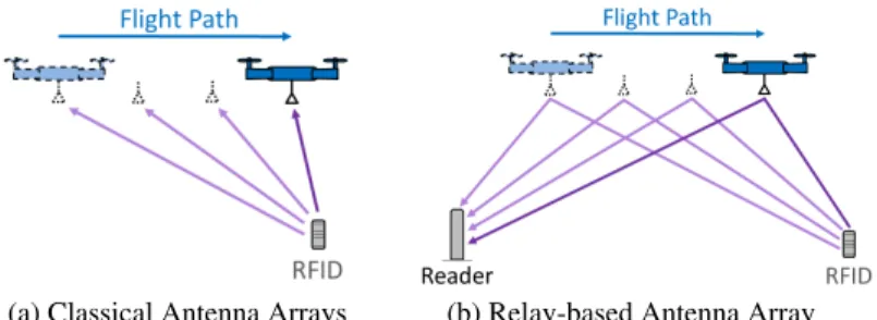
In this paper, we present RFly, a system that combines the agility of drones with the sensing capabilities of RF signals, enabling drones to detect and localize objects in non-line-of-settings and over a wide area. To realize this vision, RFly introduces a new relay technology, designed particularly for battery-free networks. The relay can seam-lessly integrate with an already deployed RFID infrastructure, as shown in Fig. 1. When a reader transmits a query, the relay picks it up, forwards it to an RFID then forwards the RFID’s reply back to the reader. As the drone flies, it can scan an entire warehouse, seamlessly extending the range of an already deployed infrastructure and eliminating its blind spots.
RFly’s relay needs to satisfy three key properties:
• First, it must be bidirectionally full-duplex. In particular, backscatter communication is full-duplex in nature (RFIDs communicate by reflecting a reader’s signal). Hence, to en-able backscatter communication, RFly’s relay must support four concurrent wireless transmissions as shown in Fig. 1. • Second, the relay needs to preserve the phase and timing
char-acteristics of the forwarded packets. This is necessary because
1Similarly, RFID localization proposals in the academic community run their
Reader
Drone with Relay
RFID Self-Interference
Figure 1: RFly overview and the self-interference challenge. The packets forwarded by the relay on the uplink and downlink feed back into its antenna, causing self-interference.
(a) Classical Antenna Arrays (b) Relay-based Antenna Array Figure 2: Challenge of phase entanglement. (a) In traditional antenna arrays, the phase measurements correspond to a direct link between the RF source and the antenna. (b) When the reader obtains the phase through the relay, the phase is an entanglement of two half-links: one between the relay and the drone and another between the relay and the RFID.
accurate localization hinges on phase measurements [24, 45, 46, 48].
• Finally, it must be compact to be mounted on a drone. To realize these properties, RFly’s relay adopts a mirrored archi-tecture that has two main components. The first component performs self-interference cancellation to enable bidirectionally full-duplex communication. In contrast to past full-duplex relay proposals [15], the cancellation is done entirely in the analog domain in order to preserve the timing characteristics of the forwarded packets. Un-fortunately, the cancellation inadvertently introduces random phase and frequency offsets that can preclude localization. The second component compensates for these offsets by exploiting the fact that it can control both the uplink and downlink forwarding hardware (since they are co-located on the drone). Hence, it subtracts on the uplink the exact (phase and frequency) offsets that it inadvertently adds on the downlink. This mirrored architecture enables the reader to capture the phase of the RFID’s response through the relay and is described in detail in §4.
Now that we can capture the phase of the RFID’s response, we may proceed to localization. In particular, as the drone flies, the relay captures RFID responses at different points along its trajectory, emu-lating an antenna array as shown in Fig. 2(a). However, relay-based localization exhibits a fundamental difference from all past work on antenna arrays. Since the reader obtains phase measurements through the relay, the measured phase does not consist of a single link (direction) as in typical antenna array scenarios. Rather, the phase is an entanglement of two half-links: one between the reader and the relay and another between the relay and the RFID tag, as shown in Fig. 2(b).
RFly’s solution to this challenge consists of embedding an RFID into the relay itself. This enables it to isolate each of the two half-links and process each of them independently. At a high level, RFly’s disentanglement protocol queries both the on-board RFID and other RFIDs in the environment to capture their phases. This effectively provides it with two equations and two unknowns. It can then solve these equations to recover the two half-links. Having isolated the phases for each of the half-links, RFly may proceed to applying standard antenna array equations on each of the half-links for local-ization. In §5, we elaborate on this idea and describe how RFly’s algorithm can deal with additional challenges due to multi-path reflections in the environment.
We built a prototype of RFly. To implement the relay, we built RFly’s hardware design into a custom PCB circuit and mounted it on a Parrot Bebop2 drone [23]. We implemented an RFID reader on USRP N210 software radios [6] and used the Alien Squiggle passive RFID tags [12] for evaluation. Our experimental evaluation demonstrates the following results:
• Read Range: RFly’s relay significantly extends the range over which a reader can communicate with off-the-shelf passive RFIDs. Our stress-test experiments demonstrate that a reader can achieve 100% read rate when an RFID is over 50 m away even in non-line-of-sight environments and through walls; this represents over10× range improvement over scenarios where the relay is absent.2
• Localization Accuracy: RFly’s median localization error is 19 cm and90th percentile error is 53 cm. The localization accuracy decreases with distance due to SNR reduction but remains sub-meter even when the localized RFID is over 50 m from the reader.
RFly’s relay has few additional desirable features that make the system amenable to immediate deployment. First, it is transparent to the RFID protocol. This enables it to naturally scale already deployed infrastructures of RFID readers in warehouses, stores, or factories without requiring any modification. Second, it is lightweight and can be miniatured further into a single integrated circuit. This allows us to mount the entire relay on a small drone, which is safe to fly indoors in warehouses and factories. In contrast, none of today’s commercially available readers can be mounted on small drones and would instead require larger drones that are only safe to fly in outdoor environments or away from humans [19, 41]. Finally, RFly’s design incorporates a mechanism that enables it to automatically manage interference from multiple readers within its radio range. Contributions: We make the following contributions:
• We present the first system that leverages drones as relays for battery-free networks. The system enables drones to detect and localize objects in non-line-of-sight settings and over a wide area.
2The distance gain comes from the reader-relay half-link (which is similar to a standard
WiFi link) because the relay is powered-up by the drone’s battery. In contrast, the distance between the RFID and the relay remains limited to few meters since the relay must power up the tag and deliver sufficient modulation depth for communication.
• We design and build the first phase-preserving and bidirec-tionally full-duplex relay.
• We introduce a new localization algorithm that operates on RF signals obtained through a mobile relay.
• We present a prototype implementation of our system demon-strating its accuracy and range of operation.
RFly has a few limitations that are worth noting. First, the drone still relies on vision-based systems for navigation, obstacle avoid-ance, and stability. While this does not prevent RFly from localizing RFIDs in non-line-of-sight, it requires optical markers that can guide the drone’s navigation. Second, the localization range is still lim-ited to few tens of meters. We believe that these limitation can be addressed as the research evolves and hope that RFly’s design motivates new systems that synergize drone technologies with RF capabilities and battery-free networks.
2
PRIMER
Passive RFIDs are battery-free tags which communicate with a de-vice called a reader. A reader bootstraps communication by sending a query on the downlink channel. The query serves both as a mecha-nism to power up the tag and a means to communicate messages to it. A powered up tag responds with its unique identifier through ON-OFF keying modulation. To do so, it switches its internal impedance between two states: reflective and non-reflective.
State-of-the-art localization techniques [32, 45, 46] operate on the phase of the received tag response, which encodes distance information. Specifically:
•On the downlink, after transmitting a query, the reader trans-mits a continuous wave at some frequencyf , which can be expressed as:
x (t ) = ej2π f t (1) •On the uplink, the RFID modulates the wave with some sig-nals(t ), and the signal received at the reader can be expressed as:
y(t ) = s(t)ej2π f (t −2d/c ) (2) where2d corresponds to the round-trip distance from the reader to the tag andc is the speed of light.
Upon demodulation, a reader can recover the phase of the received signal asϕ = 4πd/c and use it for localization.
Finally, we note that the communication range between the reader and the tag is limited on the downlink channel. This is because the reader must deliver sufficient power to the RFID (around -15 dBm for off-the-shelf tags [12]) and modulation depth so that it may power up and decode. This limits the reliable range of passive RFID communication to 3-6 m [12, 42].
3
RFLY OVERVIEW
RFly is a system that leverages drones as relays for UHF RFID networks. The system can detect and localize RFIDs that are sep-arated by tens of meters from an RFID reader, i.e., much larger than the read range of a typical reader. RFly works in both line-of-sight and non-line-of-line-of-sight environments, enabling us to localize occluded RFID-tagged objects in highly cluttered environments such as warehouses, stores, and factories.
In order to localize objects in the environment, RFly dispatches a drone that navigates throughout the area of interest following a
predetermined flight plan. The drone has an on-board RFID relay, which acts as a transparent intermediary between RFID readers and RFID tags in the environment, as shown in Fig. 1. As the drone flies, the relay continuously forwards uplink and downlink traffic between the readers and the RFIDs. In §4, we describe how RFly’s relay forwards the packets in the analog domain to preserve localization-sensitive characteristics of the signal.
The RFID reader collects the responses obtained through the relay, and decodes the responses to identify the RFIDs’ unique IDs. In §5, we describe how a reader can localize RFIDs in the environment by synthesizing the measurements collected along the drone’s trajectory. Finally, to identify the localized objects, the system leverages a local database that maps each RFID’s unique ID to the object it is attached to. Such databases are typically provided by a manufacturer and map each object to its RFID’s unique identifier [1].
Before describing the details of RFly’s design, it is worth consid-ering a simple alternative: Why not mount an entire RFID reader on a drone and use it for localization in battery-free networks? RFly is superior to such a design for three main reasons:
• Ability to use indoor drones: Today’s commercially available indoor drones, such as the Parrot Bebop, can only carry a very limited payload – between few to tens of grams [22, 23]. Because RFly’s relay weighs only 35 grams, RFly can leverage these drones; hence, it is safe to operate indoors and near humans. In contrast, the lightest-weight standalone UHF RFID readers available on the market today weigh over 0.5 kg [8]. Sustaining such a payload would require relatively larger drones which are restricted to outdoor environments and are unsafe to fly near humans [19, 41].
• Interference management: Many of today’s factories and warehouses are already outfitted with an infrastructure of RFID readers. RFly can extend such an infrastructure and incorporates mechanisms that allow us to manage interfer-ence, while remaining transparent to the RFID communica-tion protocol. In contrast, a flying indoor RFID reader would introduce additional interference and result in more collisions with an already deployed infrastructure. Addressing such in-terference would require changing the RFID protocol. • Generality of the proposed techniques: Finally, it is
impor-tant to note that RFly’s contributions extend beyond the spe-cific problem of drone-based localization in battery-free net-works. In particular, the bidirectionally full-duplex capability can extend the coverage of battery-free networks even if in static settings. Moreover, the phase-preserving design and the through-relay localization algorithm extend beyond battery-free networks to various types of wireless networks. The following sections describe RFly’s relay design and drone-based localization algorithm.
4
RELAY DESIGN FOR BACKSCATTER
COMMUNICATIONS
Recall from §1 that RFly’s relay must be bidirectionally full-duplex, and it must preserve the phase and timing characteristics of the forwarded packets to enable localization. In this section, we de-scribe RFly’s relay design; then, in §5 we dede-scribe how it performs localization through the relay.
Figure 3: Four sources of self-interference. The relay suffers from self-interference between each of its transmit and receive chains.
4.1
The Challenge of Self-Interference
The key challenge in designing RFly’s relay is self-interference. To understand this challenge, let us consider the simplest relay design, shown in Fig. 3. In order to preserve the phase and timing character-istics of the forwarded packets, the relay may simply amplify and forward the received packets without performing digital manipula-tion. However, such an approach results in self-interference, whereby the forwarded packets feed back into the relay’s receive antennas. Based on fundamental principles in control theory, this amplified feedback drives the relay into an unstable state whereby it rings as its output feeds back into its input [15]. This problem is exacerbated by the fact that RFID communication is full-duplex in nature since RFID tags communicate by reflecting the reader’s signal. As a result, the relay simultaneously suffers from self-interference on both the uplink and the downlink as can be seen in Fig. 3.
To overcome this challenge, RFly must address two types of self-interference:
(1) Inter-link self-interference, which refers to the interference between the uplink and downlink forwarding pathsInterud andInterduin Fig. 3.
(2) Intra-link self-interference, which refers to the interference between the transmit and receive antennas on each of the uplink and downlink processing paths separately, denoted by IntrauandIntradrespectively in Fig. 3.
Isolation vs. Communication Range. Before delving into how RFly addresses these two types of self-interference, it is worth noting that the amount of achieved isolation (i.e., self-interference cancella-tion) directly impacts the communication range between the relay and the RFID reader. Specifically, to ensure that the relay does not oscillate, the signal arriving from the reader must be greater than the leakage from the relay’s transmit antennas. Hence, the path lossL between the reader and the relay must be smaller than the isolationI between the transmit and receive antennas. Mathematically, since path loss can be expressed as a function of the rangeR and the wavelengthλ, the following inequality must be satisfied:
I > L = 20 log (4πR/λ) (3) R/λ < 10I /20/(4π ) (4) The inequality demonstrates that in order to achieve larger range, we need to achieve higher isolation. Numerically, an isolation of 30dB
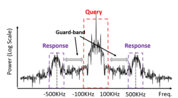
Figure 4: RFID communication frequency response. The figure shows that the reader and tag’s frequency responses are separable by a guard-band in the frequency domain.
results in a range of 0.75 m, while an isolation of 80dB results in a range of 238 m.
Next, we describe how RFly addresses the two types of self-interference.
4.2
Addressing Inter-Link Self-Interference
We start by addressing the self-interference between the uplink and the downlink relay paths. Recall that an RFID responds by reflecting the signal transmitted by the reader. Hence, both uplink and down-link are at the same frequency. This results in leakageInterduand Interudin Fig. 3.
RFly’s solution to this challenge exploits the signal structure of RFID communications in the frequency domain. Specifically, it ex-ploits the fact that the reader’s query (on the downlink channel) and the RFID’s response (on the uplink channel) occupy different sub-bands around the center frequency used for communication. Fig. 4 illustrates this property by overlaying the frequency response of the reader’s query and the RFID’s response. The figure demonstrates a gap, which is called the guard-band, in the signal spectrum between uplink tag response and downlink query from the reader to the RFID. For example, the EPC Gen2 protocol allows an RFID tag backscat-ter link frequency (BLF) as high as 640kHz while the spectrum of reader to tag query command is constrained within 125kHz.
RFly’s design takes advantage of the guard-band by implementing filters on the uplink and downlink relays. Note, however, that since the frequency difference between the uplink and downlink is very small (tens of kHz) in comparison to the center frequency (around 900MHz), implementing such filtering in passband (i.e., around the center frequency) would require extremely high quality-factor filters, which are unavailable on the market. Instead, we adopt a downconvert-upconvert approach and filter in baseband.
For simplicity, let us start with the downlink channel (from the reader to the tag). This channel occupies a small bandwidth around the center frequency, as shown in Fig. 4. RFly downconverts the received signal to baseband, low-pass filters, then upconverts before transmitting it to the tag. Through this filtering, it prevents the re-layed response’s self-interference, which is denoted asInterud in Fig. 3 from leaking into the downlink relay channel. Similarly, on the uplink channel (from tag to reader), RFly downconverts to baseband, then bandpass filters around the tag’s response, then upconverts back.
A natural question is: how can the relay discover the reader’s center frequency? Specifically, a reader may send a query at any frequency within the 900 MHz ISM band for UHF RFID commu-nications, and the relay needs to figure out that frequency in order to downconvert and filter in baseband. In contrast to performing a standard Fourier transform – which would require digitizing and processing the signal at tens of MHz of bandwidth – RFly emulates the behavior of the Fourier transform through a simple energy de-tection and correlation mechanism. In particular, the relay gradually sweeps the center frequency for downconversion, correlates with all the possible center frequencies within the ISM band, and chooses the frequency where the correlation peaks. Mathematically, if the incoming signal isx (t ), we can express the operation as:
ˆ fc= arg max f X t x (t )e−j2π f t (5) Note that in contrast to a Fourier transform which would first digitize and storex (t ) then perform the transform operation, RFly’s approach is akin to a streaming algorithm that operates on contiguous 1-ms chunks of the reader’s transmitted wave. In practice, the entire sweeping operation takes 20 ms, after which, the relay locks onto the frequency of the reader.3
4.3
Addressing Intra-Link Self-Interference
Next, we describe how RFly addresses intra-link interference, i.e., the interference due to the leakage between a given relay’s transmit and receive antennas. This is denoted byIntrauandIntradin Fig. 3. RFly’s solution to this challenge is an out-of-band full-duplex de-sign, i.e., the relay transmits at a signal whose frequency is different from the one it receives at. To do so, it leverages the downconvert-upconvert approach described in §4.2. For example, on the downlink channel, it downconverts with the reader’s center frequency but up-converts with another frequencyf2, effectively achieving frequency
division between the reader-relay link and the relay-RFID half-link.
Note, however, this downconvert-upconvert strategy breaks the co-herent nature of RFID communication. Said differently, this strategy distorts the phase of the RFID’s response, which is particularly prob-lematic since localization relies on accurate phase measurements. Specifically, since the relay and the reader have different oscilla-tors, they are not synchronized and as a result, the relay introduces a carrier frequency offset (CFO) and phase offset into the signal. Mathematically, the relay generates some frequencyf′different than the reader’s frequencyf , and introduces a random, unknown phase offsetϕo to the downlink signal. We can express the time-varying induced phase as:
ϕ′(t ) = 2π (f − f′)t + ϕ
0 (6)
To address this challenge, we leverage the fact that RFly has con-trol over both the downlink and uplink relays. Hence, we design the uplink forwarding path such that it inverts the effect of the downlink path by mirroring its behavior. Specifically, on the uplink processing path, it upconverts with the same oscillator used for downconversion
3Note that in certain regions of the world, the regulations dictate that the reader hops
frequencies every half second according to a prespecified pattern. Once the relay iden-tifies the center frequency at a given point in time, it can lock onto the same hopping pattern. [2]
on the downlink relay. This induces a phase shift −ϕ′(t ), which
cancels the effect of the oscillator discrepancies between the relay and the reader. Such an approach restores the coherent nature of the communication link and allows the relay to act as a transparent intermediary between the reader and the RFIDs in the environment.
A few additional points are worth noting:
• In the presence of multiple RFID readers in the environment, the relay automatically selects the frequency of the reader with the strongest receive signal as per Eq. 5. Once it locks onto the corresponding reader’s center frequency, the base-band filters on the downlink and uplink filter out the signals of all other readers, naturally managing the interference.4 • The above discussion focuses on the operation of a single
relay. In practice, RFly’s design can extend to multiple relays, which may be daisy chained. The system architecture and analysis of such a system are outside the scope of this paper. • Finally, in contrast to past relay architectures which can achieve up to2× range extension between communicating nodes, RFly’s relay enables increasing the communication range by orders of magnitude between the reader and RFIDs in the environment. This owes primarily to the fact that battery-free RFIDs rely on the signal received on the down-link channel to power up, typically requiring about -15dBm of received signal strength [12]. This requirement limits the path loss budget on the downlink channel; as a result, existing readers have a maximum range of few meters [47, 50]. In contrast, by employing a relay, we can decouple the commu-nication range from the powering up range in passive RFID communications. Specifically, while the half-link between the relay and an RFID remains limited to few meters, the range between the relay and the reader is only limited by our iso-lation ability (as evident from Eq. 4). In §7, we demonstrate how we can achieve multiple tens of meters in range.
5
THROUGH-RELAY LOCALIZATION
In this section, we describe how RFly can localize a single RFID by mounting our relay on a drone. The same technique generalizes to a large number of tags in the environment.
RFly’s approach builds on past work on synthetic aperture radar (SAR) [17, 28, 45]. Specifically, as the drone flies, the relay cap-tures the RFID responses from different locations along the drone’s trajectory, and treats these spatial measurements as an antenna ar-ray. Subsequently, by applying antenna array equations to these measurements, it can localize the RFIDs.
While our approach is inspired by SAR, it faces two key chal-lenges which are unique to our system architecture:
(1) Phase entanglement: First, since the reader obtains phase measurements through the relay, the measured phase does not consist of single direction as in typical antenna array scenarios (e.g., Fig. 2(a)). Rather, the phase consists of two half-links: one between the reader and the relay and another between the relay and the RFID tag, as shown in Fig. 2(b). In order to apply antenna array equations, RFly must first disentangle
4In the event that multiple readers transmit at the same frequency, we can leverage past
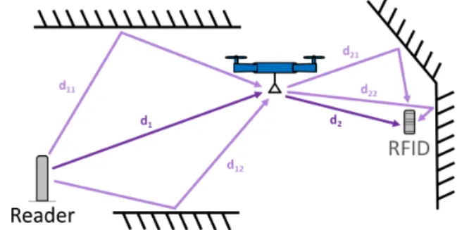
Figure 5: Multipath. The signals bounce off various objects in the environment on each of the two half-links, complicating localization. the two half-links and distill the phases corresponding to the relay-RFID link as we describe in §5.1.
(2) Multipath: The second challenge stems from multipath in the environment. Specifically, the packets traveling on each of the links do not arrive only on the direct line-of-sight between the nodes. Rather, they bounce off of different objects in the environment, including walls and furniture, as shown in Fig. 5. This problem is exacerbated by the fact that the direct path on each of these links may be significantly attenuated by an obstacle (e.g., furniture). As a result, the direct path may not always be the path with the strongest signal. In §5.2, we describe how RFly leverages the structure of indoor multipath to identify the direct path and localize the RFIDs.
In what follows, we discuss how RFly addresses each of these challenges.
5.1
Disentangling the Phase Half-Links
We start by characterizing the problem of the phase entanglement before we delve into the solution.
Phase Received through the Relay. Let us start by assuming that there is a single direct (line-of-sight) path from the reader to the relay (with distanced1) and a single path from the relay to the reader
(with distanced2). Mathematically, it follows from Eq. 2 that we can
express the channel of the signal received at the reader as:
hLOS= e−j2π (f (2d1/c )+f2(2d2/c )) (7)
wheref and f2correspond to the frequencies of the signals on each
of the half-links as explained in §4.2.5
In practice, however, due to indoor multipath, the packets traverse multiple paths on each of the half-links, whose distances we denote d1iandd2irespectively, as shown in Fig. 5. Due to the superposition of signals over the wireless medium, the different paths linearly combine at the receiver. Hence, in the presence of multipath, we may express the received channel at the reader as:
h =X
i
X
j
e−j2π(f (2d1i/c )+f2(2d2j/c )) (8)
Since each of the paths on the first half-link traverses all the paths of the second half-link and vice-versa, we may re-factor the above
5Note that, in practice, the effect of the second half-link would bef
2+ f′−f . However,
f′−f is less than few hundred Hz; hence, it is negligible in the channel estimates.
equation as follows: h =X i e−j2π f (2d1i/c )X j e−j2π f2(2d2j/c ) (9)
The equation shows that even if we know the location of the drone, we still cannot isolate the phase of the relay-RFID half-link. This is because the position of the drone would only allow us to estimate the impact of the direct path on the reader-relay channel but not that of the multipath. As a result, even if we factor out this impact, we still cannot isolate the relay-RFID half-link because of the residual multipath on the reader-relay half-link.
Embedding an RFID into the relay. Next, in order to separate the two half-link channels, we embed an RFID into our relay itself. (Note that even if the embedded RFID is outside the reading range of the reader, the reader may still capture its phase through the relay.) Since the on-board RFID and the relay are co-located, the RFID’s channel as recorded by the reader reduces entirely to the half-link between the reader and the relay.6Hence, in order to eliminate the impact of the reader-relay half-link, the reader may simply divide the channel of any given RFID by the channel of the relay-embedded RFIDhb. The resulting equation becomes entirely a factor of the half-link between the relay and the RFID in the environment as shown below: h′= h hb = X j e−j2π f (2d2j/c ) (10)
Aside from enabling RFly to eliminate the impact of the half-link between the reader and the relay, this approach provides two additional interesting features. First, since we embed the RFID into the relay, it abides by the EPC Gen2 protocol which enables RFly to naturally avoid collisions between the relay-embedded RFID and other RFIDs in the environment. By storing the identifier of the relay-embedded RFID on the reader, the reader can always distinguish it from other RFIDs in the environment. Second, while the relay-embedded RFID will likely be out of the range of the reader itself, it is always within the range of the relay. Said differently, the relay-embedded RFID can always be powered up by the relay since it is in close proximity to the relay’s antennas on the drone. Hence, whenever the reader receives a response from the relay-embedded RFID, it knows that the drone’s relay is within its radio range. This enables the reader to identify when the relay itself is within its radio range whenever it can decode the relay-embedded RFID.
Finally, we note that since the channel of the relay-embedded RFID consists entirely of the half-link between the ground-based reader and the relay, this channel may be used to localize the drone itself by leveraging standard SAR equations. However, localizing the drone itself solely from RF measurements is outside the scope of this paper. Instead, in this paper, we rely on accurate vision-based systems for localizing and navigating the drone.
5.2
Localization Algorithm
Now that we have isolated the channel corresponding to the half-link between the relay and an RFID in the environment, we can proceed to localizing the RFID.
6In practice, it still has a multiplicative constant which does not change as the drone flies
since the distance between the relay-embedded RFID and the relay remains constant. As a result, we can ignore that constant since it does not affect the antenna array equations and can be factored out.
At a high level, RFly leverages the fact that the drone’s movement emulates an antenna array and applies standard array equations to perform localization. Antenna arrays exploit small phase changes due to distance in order to localize an object of interest. The literature on antenna arrays discusses various formulations [37]. Among these, non-linear projections are the most suitable for RFly since they can synthesize RF measurements over long trajectories.
For simplicity, let us focus on how this localization method works in 2D space. Intuitively, this formulation leverages the fact that every point(x,y) in 2D space can be described by a set of distances from the different points along the drone’s trajectory. Hence, to localize, it applies a matched filter on all possible locations and chooses the highest peak.7
Mathematically, considerK locations along the drone’s trajectory where it captures responses from a given RFID. If the coordinates of these points are(x1,y1) . . . (xK,yK), and the isolated channels for a given RFID are(h′1. . . h′K), the 2D location of the RFID may be estimated as:
( ˆx, ˆy) = arg max
(x,y)P (x,y) (11) where P (x,y) = K X l=1 h′ lej2π f c2 √ (x−xl)2+(y−yl)2 (12) Fig. 6(a) depicts an example where the RFID is in line-of-sight of the relay. The figure shows a heatmap ofP (x,y) in 2D space, where red indicates high likelihood of the RFID’s location and navy blue indicates low likelihood. The white triangle indicates the actual location of the RFID, and the cyan line marks the robot’s trajectory. We make the following observations from this experiment:
• RFly’s estimated location of the RFID (denoted by the peak of this heatmap in dark red) is very accurate relative to the RFID’s actual location, with an error less than 7 cm. • The heatmap exhibits few light blue patches. These are due
to environmental noise as well as the sidelobes of the antenna array projections.
• RFly can obtain an RFID’s 2D location from a 1D trajectory since it leverages non-linear projections in Eq. 12.
The above example demonstrates that RFly can estimate an RFID’s location by simply picking the peak inP (x,y) when the line-of-sight path is the most dominant. However, indoor environments are abound with multipath due to the various reflectors (walls, furniture, ceil-ings, etc.). Fig. 6(b) showsP (x,y) for an experiment run with heavy multipath due to steel shelves in the surrounding environment. The figure shows multiple dark red regions, indicating various potential positions for the RFID.
To address multipath, RFly’s underlying insight is that indirect reflections (caused by reflectors) always arrive along a longer path than the direct path from the RFID to the relay. Hence, the “ghost” locations caused by multipath reflections are always further from the robot’s trajectory than the actual tag location. RFly harnesses this insight in its localization process. In particular, rather than picking the highest peak in Eq. 12, it chooses the peak nearest to its trajectory.
7The literature also discusses multi-resolution algorithms for optimizing the search,
which we omit in our discussion for brevity and refer the interested reader to [9, 37, 46].
-0.5 0 0.5 1 1.5 2 2.5 3 x-axis (meters) -0.5 0 0.5 1 1.5 2 2.5 3 Y-axis (meters) Drone flightpath Actual tag location
-0.5 0 0.5 1 1.5 2 2.5 3 x-axis (meters) -0.5 0 0.5 1 1.5 2 2.5 3 Y-axis (meters) Drone flightpath Actual tag location
Multipath image
(a) Line-of-sight (b) Strong Multipath Figure 6: RFly’s localization. The figures plotP (x,y) as a heatmap, where red indicates high likelihood of the RFID’s location and navy blue indicates low likelihood. The white triangle indicates the actual location of an RFID and the cyan line denotes the drone’s trajectory used for localization.
Finally, we list a few interesting features of RFly’s localization algorithm:
• While the above localization method was described in 2D for simplicity, it can be extended to 3D if the robot’s trajectory is two-dimensional.
• RFly’s localization accuracy improves when integrating Eq. 12 over longer trajectories as we show empirically in §7.3. This is because a larger aperture results in narrower beamwidths for localization [9, 37]. In practice, however, the integration path is limited to 3-5 meters due to the limited communication range between the relay and the RFID tag.
• The above localization algorithm naturally extends to multi-ple tags in the environment. In particular, the standard RFID protocol (the EPC Gen2) can read multiple tags, and our algorithm operates on the channels of each of the tags inde-pendently.
• Aside from the ability to accurately localize RFIDs, RFly’s approach of leveraging drones does not suffer from blind spots which are typically very challenging with stationary RFID readers (due to destructive interference or orientation mismatch) [31]. This is because the drone can capture each RFID’s response from different perspectives.
• RFly’s algorithm can seamlessly deal with scenarios where an RFID is within the communication range of both the relay and an RFID reader in the environment. In such scenarios, the channel from the (stationary) reader to the RFID remains constant, while that from the relay to the RFID varies due to motion. As a result, the constant channel is factored out by Eq. 12 and does not affect the localization results.
• It is worth noting that the reader may still use f in Eq. 12 despite the fact that the isolated channel is measured atf2.
This owes to the fact that the relay can ensure that (f − f2)/f < 0.01 by shifting the center frequency by as little as
1MHz while still ensuring that the half-links do not interfere as explained in §4.3.
(a) RFly’s relay circuit (b) Bebop2 drone
Figure 7: RFly’s relay circuit and drone. (Note: images not to scale). The custom-designed PCB in (a) measures10 × 7.5cm and is attached to the drone shown in (b) which measures32 × 38cm.
6
IMPLEMENTATION & EVALUATION
We built a prototype of RFly. The system consists of a lightweight relay which can be mounted on drone and used to detect and localize battery-free UHF RFIDs.
6.1
Hardware Prototype of RFly’s Relay
We built RFly’s relay, discussed in §4 into a custom designed PCB circuit shown in Fig. 7(a). The circuit schematic is shown in Fig. 8. Mirrored Architecture: Recall that the relay has a mirrored archi-tecture in order to compensate for frequency and phase offsets. The relay consists of two paths: the downlink forwarding path and the uplink forwarding path. Each path employs two RF mixers. The first mixer downconverts the signal to baseband while the second mixer upconverts the baseband signal back to passband. The frequencies for upconversion and downcoversion are generated by frequency synthesizers.
Self-interference Cancellation: Self-interference cancellation is achieved through a combination of frequency shifts and baseband fil-ters. Specifically, the relay eliminates inter-link interference through baseband filtering. In particular, a low-pass filter with cut-off fre-quency at 100kHz and a bandpass filter with center frefre-quency at 500kHz are implemented in the downlink and uplink respectively. As a result, the baseband filter only allows the reader’s query command to pass on the downlink; and, the bandpass filter only allows the RFID tag’s response to pass on the uplink. Together, the baseband and passband filters effectively block the reader’s query signal from leaking from the downlink path to the uplink path and block the RFID tag’s response from leaking from the uplink path to the down-link path, achieving high inter-down-link isolations. To eliminate intra-down-link interference, the relay uses different frequencies for downconversion and upconversion. The frequencies are separated by a frequency shift larger than the bandwidth of both the lowpass and bandpass filters to ensure that no signal feeds back from the output to input on each of the downlink and uplink paths, resulting in high intra-link isolation.
Tunable Amplification: Both the downlink and uplink have an amplification chain which is implemented as a serial combination of amplifiers and matching pads. The downlink also employs a power amplifier (PA) at the output with a 1-dB compression point of 29dBm.
Figure 8: RFly’s relay schematic. The relay has a mirrored archi-tecture to eliminate phase and frequency offsets that would otherwise preclude localization.
To maximize the efficiency of the PA, we insert a drive amplifier. All amplifiers aside from the PA are variable gain amplifiers (VGA) so that the gain in each stage can be tuned independently according to the communication range needed. Few points are worth noting about how the VGAs are programmed:
• The total gain on each of the uplink and downlink is inde-pendently constrained by the amount of intra-link isolation. This ensures that each of the links does not resonate through positive feedback.
• The sum of all the gains (in Fig. 8) is constrained by the total achievable isolation from both the inter-link and intra-link self-interference cancellation.
• Since the communication range with battery-free RFIDs is primarily limited by the downlink (which must deliver suffi-cient power and modulation depth to an RFID), the downlink gain should be maximized subject to the above constraints. • Maximizing the gain on the downlink (as per the previous
point) results in very high power at its output (i.e., the relayed query atf2in Fig. 8). This creates a risk of saturation at the
input of the uplink. We mitigate this problem by shifting most of the uplink gain to the output of the uplink path, i.e., after the baseband cancellation from the bandpass filter in Fig. 8. Fabrication and Physical Dimensions: We implemented our de-sign on a 4-layer FR-4 PCB using standard commercial components. High dielectric ceramic antennas are chosen to minimize the system size. The final size of our relay is 10cm x 7.5cm and the total weight is 35g. Our current design employs four antennas for ease of testing and debugging. The number of antenna can be reduced to two by utilizing two circulators shared between the downlink and uplink.
6.2
Integrating the Relay with a Commercial
Drone
RFly’s relay is mounted on a Parrot Bebop 2 drone [23] shown in Fig. 7(b). The Bebop 2 is a low-cost commercial drone. The present retail price is $499. The overall dimension of Bebop 2 is32 × 38cm, and it can carry a maximum payload of 200g.
We use the drone’s battery to power RFly’s relay. Because the relay requires a 5.5 V DC power supply while the drone’s battery output is 12 V, we insert a DC-to-DC converter between the drone’s battery and the relay. The converter is connected to the anode and cathode of the battery via secondary wiring. The relay’s total power consumption is 5.8 Watts, drawing 0.49 Amps current from the
0 0.2 0.4 0.6 0.8 1 0 20 40 60 80 100 120 140 CDF Isolation (in dB) RFly Analog Relay
0 0.2 0.4 0.6 0.8 1 0 20 40 60 80 100 120 140 CDF Isolation (in dB) RFly Analog Relay
0 0.2 0.4 0.6 0.8 1 0 20 40 60 80 100 CDF Isolation (in dB) RFly Analog Relay
0 0.2 0.4 0.6 0.8 1 0 20 40 60 80 100 CDF Isolation (in dB) RFly Analog Relay
(a) Inter-downlink Isolation. (b) Inter-uplink Isolation. (c) Intra-downlink Isolation. (d) Intra-uplink Isolation. Figure 9: RFly’s Isolation from self-interference cancellation. RFly can achieve at least 50dB improvement in isolation over a traditional analog relay.
battery. Since the battery is designed to support up to 21.6 Amps, the relay consumes less than 3% of the drone’s battery.
6.3
RFID System Implementation and Evaluation
The overall system consists of RFly’s relay mounted on a low-cost commercial drone, an RFID reader which is compliant with the EPC Gen2 protocol, and off-the-shelf low-cost passive RFID tags. RFID Reader: State-of-the-art commercial off-the-shelf RFID read-ers have limitations in accurately measuring the phase with a full 360-degree cycle. For example, the ThingMagic M6e reader [4] can only report phases between 0 and 180 degrees, while the Imp-inj R420 [2] experiences 180 degrees random phase jumps. Hence, we adapt a USRP RFID reader implementation developed in [26] and incorporate RFly’s localization algorithm described in §5. The reader handles a variety of commands including the Query com-mand, ACK comcom-mand, Select comcom-mand, and QueryRep Command. We retrieve the complex channels from USRP and post-process them in MATLAB.
Passive RFID Tags: We use the Alien Squiggle General Purpose tags [12] in our evaluation, which are the current industry standard. The cost of each tag is $0.12.
Ground Truth: We use OptiTrack [5], which is an optical tracking system, as a ground truth for location measurements. The system consists of an array of infrared cameras mounted on a ceiling, and can achieve sub-cm localization accuracy in tracking objects tagged with infrared-reflective markers in its line-of-sight. The optical track-ing system serves two purposes: first, it measures the ground truth location of the target RFID tag. Second, it captures the flight path trajectory of the drone. Note that the drone’s trajectory may also be acquired from its odometry sensors.
7
RESULTS
In this section, we report the results of RFly’s evaluation.
7.1
Does RFly’s Relay Satisfy the Two Key
Properties?
First, we evaluate whether RFly’s relay satisfies its two key proper-ties: bidirectionally full-duplex and phase-preserving.
(a) Self-interference Cancellation: We evaluate the amount of iso-lation achieved on each of the four self-interference links described in §4. We run 100 experimental trials in total. In each trial, we use the USRP to generate an input signal that is fed to the relay, and we perform power measurements using a spectrum analyzer. In each
experiment, we vary the power and the center frequency of the in-put signal (within the UHF ISM band). We perform four types of experiments:
• To measureIntrad, we feedf1+ 50kHz to the input of the
downlink (to emulate a query) and measure the power at the output of the downlink atf1+ 50kHz.
• To measureIntrau, we feed f2+ 500kHz to the input of
the uplink (to emulate an RFID’s response) and measure the power at the output of the downlink atf2+ 500kHz.
• To measureInterdu, we feedf2+ 50kHz to the input of the
uplink (to emulate a the leakage of a query from downlink to uplink) and measure the power at the output of the uplink at f1+ 50kHz.
• To measureInterud, we feed f1+ 500kHz to the input of
the downlink (to emulate a the leakage of a tag’s response) and measure the power at the output of the downlink atf2+
500kHz.
We compute the isolation as the signal attenuation (between the input and output of interest) plus the gain. This allows us to factor out the gain of the circuit. We also count the isolation of the antennas toward the total isolation.
The CDFs for the isolations are shown in Fig. 9. The figures also report the amount of isolation achieved by a baseline analog relay. The baseline implements a traditional analog relay design that achieves isolation by antenna separation and polarization. Note that the antennas are spaced relatively closely (at 10cm separation) to enable a compact relay that can be mounted on a drone. Recall that RFly can only rely on analog cancellation in order to preserve phase and timing characteristics for localization.
The figures demonstrate the following findings:
• RFly’s relay achieves median isolations of 110, 92, 77, and 64dB. These consist at least 50dB improvement over a tradi-tional analog relay.
• The inter-link isolations (110dB and 92dB) are higher than the intra-link isolations (77dB and 64dB). This is expected be-cause RFly’s isolation is achieved primarily through baseband filters that are optimized for maximizing low frequency can-cellation (which is used in RFly’s inter-link isolation) rather than minimizing high frequency feed-through (which results in intra-link leakage). Note that additional RF filters can be used if higher isolations are needed.
• The downlink isolation is higher than the uplink isolation. This is because the downlink (low-pass) filter results in more attenuation than the uplink (band-pass) filter. Note that this
0 0.2 0.4 0.6 0.8 1 0 20 40 60 80 100 120 140 160 180 CDF
Phase Error (in degrees) RFly No-Mirror
Figure 10: Phase accuracy with and without the mirrored archi-tecture. RFly enables preserving the phase of the relayed signal to enable SAR-based localization.
discrepancy is benign since RFly’s relay is optimized for downlink isolation (as explained in §6.1) to enable more amplified power delivery to an RFID.
(b) Phase Preservation: Unlike conventional relay technologies which introduce random frequency and phase offsets, RFly’s relay is phase-preserving. In particular, it only introduces a constant phase offset (due to the hardware path) which can be eliminated using the drone-embedded RFID as described in §5.1.
To measure the phase-preserving capability of RFly’s relay, we place an RFID tag 0.5 m away from the relay and connect the relay over the wire to the USRP-implemented reader. We run 50 experimental trials in total. In each trial, we generate a reader’s query with a random initial phase using the USRP and feed it as an input to the downlink relay. The relay’s uplink output is also connected directly to a reader. The reader’s decoder computes the channel of the RFID and extracts its phase. We measure the offset as the phase difference between estimated channels across the different trials. We use the embedded RFID in order to factor out the effect of the hardware channel.
The CDF of the phase offset is shown in Fig. 10. The median phase error in our mirrored architecture is0.34◦and the99th per-centile error is1.2◦. In contrast, without a mirrored architecture (i.e., if the upconversion/downconversion frequencies are not locked to the same synthesizers), the phase is completely random as shown in Fig. 10. This shows that RFly can preserve the phase of an RFID’s response and use it for localization.
7.2
How Does the Overall System Perform?
Next, to evaluate that RFly can detect and accurately localize battery-free RFIDs over a wide area, we run 100 experimental trials locations throughout two floors our research facility building. The building is30 × 40m wide. Our experiments encompass both line-of-sight and non-line-of-sight settings and span three floors of our research facility.
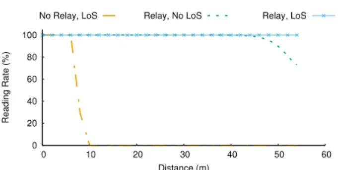
(a) Range Evaluation: To evaluate RFly’s range improvement, we run two types of experiments: one with the relay and one baseline without the relay. At each location we measure the percentage of decodable RFID tag responses to determine the reading rate.
Fig. 11 plots the reading rate as a function of distance. The figure shows that in the absence of a relay, the read rate drops to zero at a range of 10 m. In contrast, in the presence of a relay, the reader’s
0 20 40 60 80 100 0 10 20 30 40 50 60 Reading Rate (%) Distance (m)
No Relay, LoS Relay, No LoS Relay, LoS
Figure 11: RFly’s detection with range. RFly can detect RFIDs more than 50 m away from the reader with 100% accuracy in line-of-sight and 75% in non-line-line-of-sight. Without the relay, the range decreases to less than 10 m.
read rate stays at 100% even if the relay is more than 50 m in line-of-sight. In non-line-of-sight scenarios, the read rate drops to 75% at a distance of 55 m.
We note few important points about these results:
• These results are not surprising as per Eq. 4. Specifically, based on §7.1, RFly can achieve more than 70 dB isolation across each of its sources of self-interference. This translates to a theoretical range of 83 m in line-of-sight. In non-line-of-sight environments, it naturally decreases due to attenuation. • Most of the gain comes from the reader-relay half-link. Specif-ically, the relay-RFID half-link remains restricted to 3-5 m since the relay still needs to power up the tag. However, the reader-relay half link is primarily limited by isolation as de-scribed in §4.
(b) Localization Accuracy: We mount RFly’s relay on a drone and run experiments to measure the localization accuracy throughout the experimental environment detailed above. To obtain an accurate ground truth for locations, we use the OptiTrack system described in §6. The system uses infrared-reflective markers on the drone and the RFIDs in order to measure their exact locations. We ensure that the drone remains within the field of view of the OptiTrack infrared cameras. In order to test RFly throughout a large area, we vary the location of the RFID reader across two floors of our building. Throughout these experiments, the RFID of interest is placed on the ground in order to focus on RFly’s ability to perform 2D localization. To perform localization, RFly utilizes the embedded RFID tag to disentangle the phase and applies the nonlinear antenna array equation to compute target tag location in 2D space as described in §5. We perform coordinate conversion between RFly’s frame of reference and the OptiTrack’s frame of reference. We compute the localization error as the difference between the RFly-computed location and the OptiTrack computed location.
Fig. 12 plots the CDF of the localization error across 100 exper-imental trials. These results demonstrate that RFly has a median localization error of 19 cm and a90th percentile error of 53 cm. This accuracy is comparable with state-of-the-art localization sys-tems [44, 45, 48]. Moreover, in contrast to past RFID localization proposals that are limited in range to within few meters [45, 46], RFly can achieve this accuracy at10× the range of past systems. This is due to the combination of its phase-preserving relay and through-relay localization algorithm.
0 0.2 0.4 0.6 0.8 1 0 0.1 0.2 0.3 0.4 0.5 0.6 0.7 0.8 0.9 1 CDF
Localization Error (in meters)
Figure 12: CDF of localization error. RFly achieves a median localization error of 19 cm and a90th percentile error of 53 cm across all the experiments.
7.3
How Does Localization Accuracy vary with
Different Parameters?
Next, we would like to understand how RFly’s localization accuracy varies with two important parameters: flight-path aperture and dis-tance to an RFID reader. To evaluate the impact of these metrics, we run controlled microbenchmarks.
(a) Accuracy vs. Flight-path Aperture. Recall from §5.2 that a longer aperture (i.e., a longer path along which we collect RFID channel measurements) is expected to enable higher localization accuracy. This is because a larger aperture results in a narrower beamwidth for the antenna array. To understand the influence of aperture on localization accuracy, we vary the aperture provided to the antenna array equations described in §5.2. We run 20 experiments in total, each time varying the location of the target RFID but fixing the average distance between the RFID and the relay. To control for the range, trajectory, and SNR (signal-to-noise ratio), we mount RFly’s relay on an iRobot Create 2 [3] and fix the average distance between the relay and the RFID reader to around 5 m.
Fig. 13 shows the impact of aperture size on localization accu-racy, plotting the median,10th, and90thpercentile errors. The plot demonstrates that the accuracy monotonically improves with in-creased aperture size. Specifically, with an aperture of 0.5 m, the median error is around 22 cm. This error decreases to less than 5 cm with an aperture of 1 m. We notice that the median accuracy does not improve significantly beyond 1 m; however, the90thpercentile keeps improving as the aperture size increases, and the error is less than 7 cm with a 2.5 m aperture.
We also compare RFly’s localization error with an RSSI-based localization method. We provide the channels of both the relay-embedded RFID and the target RFID to the RSSI-based technique and apply the free-space propagation model to the RSS measure-ments [37] for estimating the distance from the target tag to the relay. Fig. 13 shows that even with an RSSI-based approach, RFly achieves reasonable localization accuracy with a median error of 1 m when the aperture is 2.5 m-long. However, the error from the SAR-based technique is20× lower, and the resulting accuracy is high enough to enable warehouse robots to identify the exact shelf of an RFID-tagged item for robotic manipulation.
(b) Accuracy vs. Range. Next, we would like to study the impact of the distance on the localization accuracy. To understand the impact of distance, we adjust the reader’s transmission power (and map it to the projected distance using the free-space propagation model).
0 0.5 1 1.5 2 0.5 1 1.5 2 2.5 Absolute Error (m) Aperture (m) SAR RSSI
Figure 13: RFly’s localization accuracy vs. aperture size. RFly’s accuracy improves with a larger aperture.
0 0.5 1 1.5 2 2.5 5 10 15 20 25 30 35 40 45 50 Absolute Error (m) Projected Distance (m) SAR RSSI
Figure 14: RFly’s localization accuracy vs. projected distance from the reader. RFly’s accuracy decreases with distance due to lower SNR.
We run 50 experiments in total, fixing the aperture size to 1 m. During each run, we change the location of the RFID tagged object within the testing area. We test both the SAR-based and RSSI-based localization techniques through RFly’s relay.
Fig. 14 shows the median,10th, and90th percentile errors as a function of the projected distance. The figure shows that the lo-calization error becomes larger as the distance increases. This is expected since a larger distance results in lower SNR, decreasing RFly’s ability to perform accurate measurements for localization. However, even at a projected distance of 40 m, RFly’s SAR-based algorithm can achieve a median error less than18 cm and a 90th per-centile error less than24 cm. Beyond 50 m, the 90thpercentile error in RFly increases to82 cm. This is because the SNR at this range drops below 3dB, making the phase measurements significantly less reliable. Thus, by using a more sensitive receiver or designing a relay with more isolation, RFly would be able to maintain its high localization accuracy at further distances.
8
RELATED WORK
A natural question is whether there are other approaches that can solve the problems of long-range communication and localization for battery-free networks? Past literature has explored the topics of relay designs, long-range backscatter communication, and localization. However, in contrast to RFly, none of the past proposals can solve these problems for today’s commercial passive RFIDs, leaving out the billions of RFIDs already produced and deployed. Below, we described how RFly relates to past literature in each of these areas. Relay designs. Relays (often called signal boosters or repeaters) have been traditionally designed to increase communication range or throughput between a client and an access point or cellular base
stations [15, 21, 29, 36, 52]. In contrast to all past relay designs, RFly introduces the first phase-preserving and bidirectionally full-duplex relay. Note that the loss of phase and timing information is benign for existing relays since they were intended purely for communication purposes rather than for localization. However, it is critical for RFly’s relay to preserve phase and timing information in order to localize the RFIDs.
Past full-duplex relay proposals fall into two categories: ana-log and digital [29]. Anaana-log designs simply amplify and transmit the packets [39]. As such, they suffer from the problem of self-interference and they require large physical separation (and often occlusions like walls) between the antennas to overcome that in-terference [18, 39].8In contrast to these designs, RFly’s intelligent filtering and mirrored architecture allow us to embed the entire de-sign on a miniature circuit, which we can mount on a drone. The second category of full-duplex relays are digital – i.e., require some form of digital processing of the packet symbols [15, 21, 38], which results in the loss of phase and timing information. In contrast to these past proposals, RFly’s relay preserves phase and timing in-formation on both the uplink and downlink channels, enabling it to localize RFIDs through the relay.
RF-based localization is a classical area of research in wireless networking spanning over two decades of academic research [10, 14, 24, 45, 46, 48]. Past proposals have demonstrated the ability to local-ize active transmitters (such as WiFi [24, 44, 48] or active tags [27]) and battery-free nodes (such as RFIDs [45, 46]). In contrast to active transmitters which can operate over a longer range, passive RFIDs have no batteries; hence, their communication range is limited to within few centimeters to few meters. RFly’s relay design and local-ization algorithm enable locallocal-ization at distances10× longer than past state-of-the-art RFID localization proposals.
Algorithmically, RFly is inspired by past proposals in synthetic aperture radar (SAR) [17, 28, 45]. Specifically, we leverage the drone’s motion and exploit the fact that the drone’s trajectory emu-lates an antenna array. We introduce two primary innovations over all past systems. First, since indoor drones cannot carry an RFID reader, we introduce a new relay design that enables a reader to capture the phase of the signal. And second, we develop a new localization algorithm that can operate on RF signals obtained through the relay by intelligently disentangling the phase measurements as described in §5.1.
Longer-Range backscatter communication. RFly is also related to non-localization systems that enable backscatter devices to com-municate over a long range. These proposals either require bulky and expensive battery-powered RFIDs,9or they require designing new backscatter hardware [35, 51]. In contrast, our system operates with passive off-the-shelf RFIDs which cost few cents and are widely deployed and adopted by the industry [33]. This is possible since our relay is designed to operate as transparent intermediary for RFID communications.
Drone Solutions. Recently, few startups have proposed leveraging drones in warehouse inventory control [7, 16, 20]. By mounting a barcode reader or a camera on a drone, these proposals aim to fly
8Without such separation, these proposals cannot amplify too much.
9Active RFIDs cost100 − 1000× more than passive RFIDs [13].
a drone around a warehouse to catalog the various items. The key challenge facing these vision-based techniques is that they can only work in line-of-sight environments; hence, they would miss most objects in a warehouse since items are tightly packed together. In contrast, by relying on RF signals, RFly can localize objects even if they are occluded from its field of view.
Another body of work has experimented with mounting an entire RFID reader on a drones and flying in outdoor fields to detect the RFIDs within its radio range [7, 30, 40]. However, because RFID readers and their large antennas are heavy, these proposals require larger, powerful drones (similar to delivery drones), which are unsafe to operate near humans. As such, these proposals have either been deployed in outdoor yards [7] or have been tested in safeguarded environments with no humans around. RFly differs from these past systems in technology and capability. Technologically, it introduces a new relay design that is low-power and low-weight and can be mounted on small, light drones. In terms of capability, it not only detectsRFIDs within its radio range but accurately localizes them to within tens of centimeters.
9
DISCUSSION & LIMITATIONS
RFly demonstrates new possibilities for bringing ubiquitous connec-tivity and localization to battery-free networks. However, our current prototype still has few limitations that are left for future work:
• Reliance on vision-based systems: Our current evaluation relies on vision-based systems for navigation, obstacle avoid-ance, and stability. In particular, we place infrared-reflective markers on the drone and require it to remain within the field of view of the OptiTrack’s infrared cameras; hence, the drone would need to fly high enough to remain within the cameras’ field of view. However, it is desirable to enable the drone to operate in more challenging environments. Future research could leverage RF for drone self-localization and apply the SAR equations on the channel of reader-relay half-link as de-scribed in §5.2. Moreover, it would be interesting to explore using RF signals for imaging indoor environments and aiding in obstacle avoidance.
• Operation Range: The system’s range is limited to 55 m due to the extent of self-interference cancellation. To cover a larger area, one could improve the design of cancellation circuits and algorithms by building on past work in full-duplex designs [15, 38] or MIMO techniques [11].
• Swarm Extension: RFly currently operates with a single drone. It is desirable to extend the system’s operation to swarms of drones. Future research could explore designs that daisy-chain the drone-based relays (as discussed in §4) to extend the range of operation. The phase-preserving characteristics may also be leveraged by the drones to localize other drones in cluttered environments.
Despite these limitations, RFly marks an important step toward enabling long-range communication and localization in battery-free networks. More importantly, it motivates new directions in network-ing research that combine the agility of drones with the sensnetwork-ing capability of RF signals. It also motivates new relay designs that enable communication, sensing, and localization beyond the realm of battery-free networks.