MULTIBODY DYNAMICS 2009, ECCOMAS Thematic Conference K. Arczewski, J. Frączek, M. Wojtyra (eds.) Warsaw, Poland, 29 June – 2 July 2009
DYNAMIC ANALYSIS AND PRELIMINARY DESIGN OF
TWIN-CYLINDER ENGINES FOR CLEAN PROPULSION SYSTEMS
Yannick Louvigny1, Nicolas Vanoverschelde1, Guy Janssen2, Ernst Breuer3 and PierreDuysinx1
1 LTAS – Automotive Engineering – University of Liège B52, Chemin des Chevreuils 1, B-4000 Liège, Belgium
e-mail: [email protected] 2 GDTech – Liège Science Park,
Rue des Chasseurs-Ardennais, B-4031 Angleur, Belgium 3 Breuer Technical development
Avenue de Norvège 6, B-4960 Malmedy, Belgium
Keywords: Twin-cylinder Engine, Boxer Engine, Engine Balancing, Rigid Multibody Simulation, Flexible Multibody Simulation, Stress Analysis.
Abstract. Facing environmental and energy challenges, automotive industry has to improve the fuel economy of vehicles and to reduce their polluting emissions. In this particular context, small twin-cylinder engines regain interest for using in urban cars or as prime movers in hybrid electric cars. One difficulty with engine having few cylinders (three or less) comes from the balancing of the inertia forces created by the moving parts. Several models (from simple analytical model to complex flexible multibody simulation) of different configurations of twin-cylinder engine are developed. These models allow computing the inertia forces and moments generated by the engines and computing the strains and stresses of engine components. An important step is the engine balancing by modification of the crankshaft counterweights or by addition of balance shafts. The effect of the gas pressure on the balancing and on the component’s strains and stresses is also modelled. At the end, a comparison of the different configurations of twin-cylinder engine is provided.
Yannick Louvigny, Nicolas Vanoverschelde, Guy Janssen, Ernst Breuer and Pierre Duysinx
1 INTRODUCTION 1.1 Background
Facing environmental and energy challenges, automotive industry has to improve the fuel economy of new vehicles and to reduce their polluting emissions. To make cleaner car, a strategy that is widely used nowadays is the downsizing i.e. replacing large engines by smaller ones having a higher specific power. In this particular context, small twin-cylinder engines regain interest for using in urban cars or as prime movers in hybrid electric cars. Moreover, the twin-cylinder has the advantage of needing fewer parts than a four-cylinder of the same displacement and thus being less expensive to produce. The main drawback of engines with few cylinders (three or less) comes from the balancing of the inertia forces created by the moving parts.
1.2 Objectives
The first section of this paper introduces the background and the objectives of the study. The second one describes the engine configurations that are studied, the gas pressure model and the different engine models developed. The next section discusses the most important results. Finally, a few conclusions end this paper.
The objectives of this study are:
• Developing several models (from simple analytical model to complex flexible multibody simulation) of different configurations of twin-cylinder engine
• Computing the inertia forces and moments generated by the engines
• Balancing the engines by modifying the crankshaft counterweights or using balance shafts
• Taking care of the gas pressure effect on the balancing and on the component’s strains and stresses
• Comparing the different configurations of twin-cylinder engine and determining the best suited configurations to specific applications.
2 ENGINES MODELLING 2.1 Engine configuration
The regarded types of engine (see in table 1) are in-line and boxer (opposed cylinders) engines with in-phase or out-of-phase motion of the pistons (different crankshaft configurations).
Yannick Louvigny, Nicolas Vanoverschelde, Guy Janssen, Ernst Breuer and Pierre Duysinx
In-phase Out-of-phase
In-line
Boxer
Table 1: Four configurations of twin-cylinder engines studied in this paper 2.2 Gas pressure model
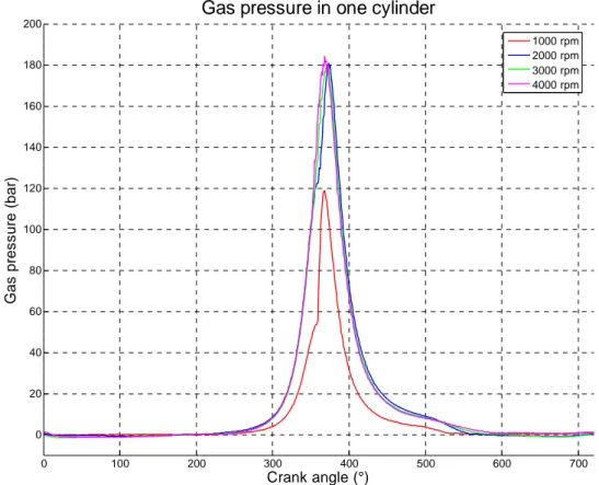
The gas pressure in the cylinder has been determined by experiments on an existing similar diesel engine by Breuer Technical Development (Ref. [1]). The gas pressure at full throttle is known for every position of the crankshaft angle between 0 and 720 degrees and for different engine speeds (see Fig. (1)).
0 100 200 300 400 500 600 700 0 20 40 60 80 100 120 140 160 180 200
Gas pressure in one cylinder
Crank angle (°) G a s p re ssu re ( b a r) 1000 rpm 2000 rpm 3000 rpm 4000 rpm
Yannick Louvigny, Nicolas Vanoverschelde, Guy Janssen, Ernst Breuer and Pierre Duysinx
2.3 Analytical model
The first model is an analytical model based on the piston motion equations. The equations of the inertia forces for one cylinder (Eq. 1 and Eq. 2) are obtained by linearization of the piston motion equations (Ref. [2]). The oscillating mass is the mass of the piston and the connecting rod (see Fig. (2)) while the rotating mass is the mass of the connecting rod and the crankshaft. The assumption is made (Ref. [3]) that one third of the connecting rod mass (small end) is part of the reciprocating mass and two thirds (big end) is part of the rotating mass (Eq. 4 and Eq. 5).
Figure 2: Piston motion, inertia forces, oscillating and rotating masses (Ref. [4]) θ ω2⋅ ⋅sin ⋅ = r y r m F (1) ...)] 6 cos 4 cos 2 cos (cos cos [ 2 4 6 2⋅ ⋅ + ⋅ + ⋅ + ⋅ + ⋅ + ⋅ =r ω m θ m θ A θ A θ A θ Fx r o (2) 2 2 y x res F F F = + (3) mr = rotating mass = m1 + 2/3 m2 (4) mo = oscillating mass= m3 + 1/3 m2 (5) ... 128 15 4 1 3 5 2 =λ+ ⋅λ + ⋅λ + A (6) ... 16 3 4 1 3 5 4 =− ⋅λ − ⋅λ + A (7)
Yannick Louvigny, Nicolas Vanoverschelde, Guy Janssen, Ernst Breuer and Pierre Duysinx ... 128 9 5 6 = λ + A (8)
This model allows calculating quickly the inertia forces and moments for each configuration of the different types of engine and highlighting the main characteristics of each ones. Several balancing solutions are also evaluated and compared with this model. Thereafter, more complex simulations are carried out with rigid and flexible multibody models but only for the in-phase boxer configuration.
2.4 Rigid multibody model
The second model is a rigid multibody model using finite element approach (Ref. [5]) in the SamcefField Mecano software (Ref. [6]). This model takes advantages of the actual geometries of engine parts coming from CAD models. The CAD drawing of the two pistons, two connecting rods and crankshaft are imported in the Samcef Field environment (see Fig. (3)). The parts are linked together using appropriate kinematic joints. First, a rigid multibody (all components are rigid) dynamic simulation is realized with an imposed crankshaft rotation speed. This simulation allows model validation and it allows also calculating the inertia forces and comparing them with the forces of the analytical model. Then, the force due to the gas pressure is added in the simulation to calculate more precisely the load that is applied on each part of the engine.
Figure 3: Geometric model of the in-phase boxer engine in Samcef Field (Ref. [7]) 2.5 Flexible multibody model, static simulation
A static simulation is carried out on the crankshaft meshed with flexible element. The load cases come from the rigid multibody simulation that has been conducted earlier. The larger forces calculated in the previous model are applied directly on the crankshaft to make first estimations of the maximum values of crankshaft strains and stresses.
2.6 Flexible multibody model, dynamic simulation
Thanks to the finite element approach that is implemented in SamcefField Mecano, a dynamic simulation is made with pistons and connecting rods modelled as rigid elements while the crankshaft is meshed as a flexible body. The links and kinematic joints used are the ones of the rigid multibody simulation. With this model, calculation of crankshaft strains and stresses during all the engine cycle is possible. Several methods to simulate the crankpins and bearing surfaces (rigid hinge, rigid-flexible contact, bushing and hydrodynamic bearing) are used and compared.
Yannick Louvigny, Nicolas Vanoverschelde, Guy Janssen, Ernst Breuer and Pierre Duysinx
3 RESULTS AND DISCUSSION 3.1 Analytical model
First, the inertia forces generated inside one cylinder are considered, in the case of an engine with no balance shaft and a well-balanced crankshaft. This means that the crankshaft and the related part of the connecting rod do not produce any inertia forces. We focus mainly on the forces in the direction of the piston motion (X direction) because there are no resulting forces in the perpendicular direction (the crankshaft is well-balanced).
Fig. (4) shows that the total force, in the X direction, is the sum of different order forces. The influence of the fourth order force is already very small and the higher order forces (>4) become negligible. The aspect of the total force curve depends mainly of the interaction between the first and second order forces. At the top dead center (0° or 360°), the first and second order forces have the same direction, so their values add to each other to reach the maximum value of the total force (10987 N). At the bottom dead center (180°), the second order force is positive whereas the first order force is negative, thus the second order force reduces the peak value of the first order force. Therefore, the total force curve is not symmetric. 0 50 100 150 200 250 300 350 -1 -0.5 0 0.5 1
x 104 Inertia forces (in the x direction) for one cylinder
Angular crankshaft position (°)
F x
(N
)
First order force Second order force Four order force Total force
Figure 4: Inertia forces (X direction) for one cylinder (rotation speed of 4000 rpm)
The forces calculated in each cylinder are added up, taking care of the position and phase shift between the two cylinders, to obtain the inertia forces and moments for the different configurations of twin-cylinder engine. Each configuration of twin-cylinder is subjected to two types of inertia loads (first or second order forces or moments).
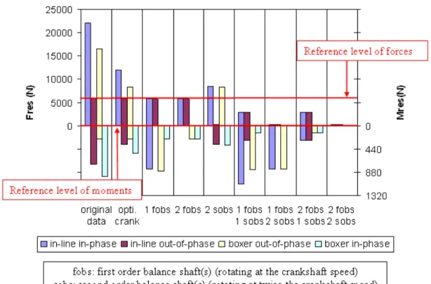
Several solutions to reduce these loads are evaluated. First, an optimisation of the crankshaft counterweights is done. Afterwards, different associations of balance shafts (first or second order balance shafts) are simulated and compared. Fig. (5) shows the maximum value of inertia forces and moments for different configurations of twin-cylinder engines. The
Yannick Louvigny, Nicolas Vanoverschelde, Guy Janssen, Ernst Breuer and Pierre Duysinx
two horizontal red lines show the maximum value of forces and moments of an equivalent (same power) four-cylinder engine in its basic configuration (without balance shaft) that serves as a reference (Ref. [8] and Ref. [9]).
Figure 5: Resulting forces and moments for different balancing systems of twin-cylinder engine
The most interesting configuration of engine is the in-phase boxer engine because it does not need to be equipped with balance shafts to reach a low level of vibrations. Some modification of the crankshaft counterweights is sufficient to have a well-balanced engine. Another solution to reduce the loadings is to reduce the distance between bore centers which is also an advantage for the size of the engine. The most interesting solutions for the other configurations of engine are: the out-of-phase in-line engine with a modified crankshaft and one first order double balance shaft, the out-of-phase boxer engine with two first order balance shafts (it is also possible in this case to reduce the distance between bore centers) and the in-phase in-line engine with two first order balance shafts.
3.2 Rigid multibody model
The first rigid multibody dynamic simulation is realized with an imposed crankshaft rotation speed of 4000 rpm and no gas pressure forces acting on the systems. At first, this simulation allows checking that the SamcefField multibody model has been properly realized (no error or warning during the simulation, the motion of each part seems correct according to a visual inspection and the values of inertia forces and moments are consistent with the values given by the analytical model).
Fig. (6) points out the position (red line), the speed (blue line) and the acceleration (green line) of one piston during three revolutions of the crankshaft (0,045 seconds). The maximum acceleration of the piston is approximately 11000 m/s². Since the oscillating mass (piston and
Yannick Louvigny, Nicolas Vanoverschelde, Guy Janssen, Ernst Breuer and Pierre Duysinx
connecting rod) weighs 0,985 kg, the maximum value of the inertia force created by one piston is 10835 N which is close to the value calculated with the equation (10987 N).
Figure 6: Position, speed and acceleration of one piston
A second rigid multibody dynamic simulation takes into account the effect of the gas pressure inside the cylinder. This gas pressure creates a force on the piston that is responsible for the useful torque of the engine. But, this force is also responsible for the important stresses inside the components and it has to be simulated to carry out strains and stresses analysis. Fig. (7) shows the forces that are transmitted from one connecting rod to the crankshaft during the working of the engine. The radial force is maximal (65000 N) during the fuel combustion when the piston is 7 degrees after its top dead center. The tangential force is maximal 24 degrees after the top dead center and its corresponding value is 36000 N.
Figure 7: Radial (red line) and tangential (blue line) force acting on one crankpin (in Newton) 3.3 Flexible multibody model, static simulation
A static simulation is done now to determine the maximal strains and stresses of the crankshaft. The forces acting on the crankshaft are known from the rigid multibody
Yannick Louvigny, Nicolas Vanoverschelde, Guy Janssen, Ernst Breuer and Pierre Duysinx
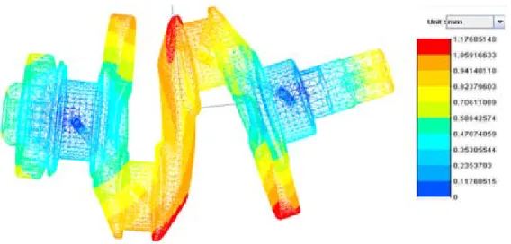
simulation and the critical load case is the one where the radial force is maximal. The value and direction of the radial and tangential forces come from the previous simulation and are applied on one crankpin. To avoid overstress problems due to a bad modelling of the force distribution around the crankpin, the forces are not applied directly on it. A flexible ring is added around the crankpin and linked to it with a contact constraint. The forces are then applied on the ring. This method gives a better modelling of the contact between the connecting rod and the crankpin. The boundary conditions are locking of the translations at crankshaft main journals using the same intermediate rings method and locking of the crankshaft rotation at one of its extremity (flywheel side). The crankshaft is then meshed with 4 mm tetrahedral elements. Fig. (8) points out the crankshaft displacement and Fig. (9) shows the stresses.
Figure 8: Crankshaft strains for the “maximal radial force” load case
Figure 9: Crankshaft stresses for the “maximal radial force” load case
As it is still close to the top dead center (7 degrees after it), the crankshaft is mainly subjected to plane bending and not to torsion. The maximal value of the displacement is 1,18 mm at the extremities of the crank webs. The stresses maximal value is higher than 1000 MPa
Yannick Louvigny, Nicolas Vanoverschelde, Guy Janssen, Ernst Breuer and Pierre Duysinx
at the fillet of the loaded crankpins. Elsewhere, the stresses reach 700 MPa in the central crank web and 400 MPa in the crankpins. These values of stresses are very high, particularly at the crankpin fillet. One reason to explain these high values come from the gas pressure model. The gas pressure that is used here is the maximum measured pressure (full speed and full throttle). Another reason is the flexible rings used to apply the forces and the boundary conditions that are only an approximation of the real contact conditions.
3.4 Flexible multibody model, dynamic simulation
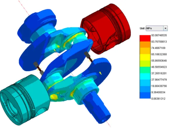
The crankshaft of the rigid multibody model is now considered as flexible and meshed with 8 mm tetrahedral elements. As noticed in the static simulation, the bearing models are critical, different models are used and compared in this section. The first simulation uses a “rigid hinge” model for the connecting rod crankshaft contacts and for the crankshaft main journals. The rigid hinge allows no translation between the two components, only the rotation is permitted. Fig. (10) illustrates the crankshaft stresses for the “top dead center” load case (piston at the top dead center at the beginning of the power stroke, there is an important radial force (45000 N) and no tangential force).
Figure 10: Crankshaft stresses for the “TDC” load case and the « rigid hinge » bearing model
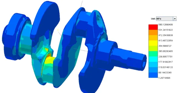
The second simulation uses a “flexible-rigid contact” model for the connecting rod crankshaft contacts and for the crankshaft main journals. This model allows defining a bore diameter slightly larger to take into account a running clearance. Fig. (11) points out the crankshaft stresses for the top dead center load case and a clearance of 50 µm at each bearing.
Yannick Louvigny, Nicolas Vanoverschelde, Guy Janssen, Ernst Breuer and Pierre Duysinx
Figure 11: Crankshaft stresses for the “TDC” load case and the « flexible-rigid contact » bearing model In the next simulation, a “radial bushing” model is used. The model is similar to the “flexible-rigid contact” model but it has a radial stiffness to slow down the translational motion of the crankshaft in the bore. The radial stiffness is used to approximate the effect of an oil film, its value is chosen constant and equal to 2*106 N/m (see Fig. (12)).
Figure 12: Crankshaft stresses for the “TDC” load case and the « radial bushing » bearing model
The last bearing model simulated is the “hydrodynamic bearing model” implemented in SamcefField Mecano. This model simulates the oil film behaviour by solving the Reynolds equation. The parameters values used for the hydrodynamics bearing are a clearance of 50 µm, a oil viscosity of 0,01 Pa.s and no cavitations (see Fig. (13)).
Yannick Louvigny, Nicolas Vanoverschelde, Guy Janssen, Ernst Breuer and Pierre Duysinx
Figure 13: Crankshaft stresses for the “TDC” load case and the « hydrodynamic bearing » model
The “hydrodynamic bearing” model is the most complete model and it is now used to determine the critical load case and the maximal values of crankshaft stresses (see Fig. (14)). This critical load case is not the “maximal radial force” load case as expected from the previous simulations but the “maximal tangential force” load case. The maximal stress value is less than 600 MPa. Compared to the 1000 MPa calculated with the static model, this value is more realistic and emphasizes the interest of good bearing models and dynamic simulations.
Figure 14 : Crankshaft stresses for the “maximal tangential force” case and the « hydrodynamic bearing » model 4 CONCLUSIONS
Each configuration of engine has its own characteristics in terms of inertia forces and moments. The in-phase in-line engine produces first and second order forces. The out-of-phase in-line engine produces second order forces and first order moments. The in-out-of-phase boxer engine generates first and second order moments. And the out-of-phase engine
Yannick Louvigny, Nicolas Vanoverschelde, Guy Janssen, Ernst Breuer and Pierre Duysinx
produces first order forces and second order moments. For all these engines, different combinations of balance shafts and crankshaft are compared in order to minimise the forces and moments.
The rigid multibody simulation allows calculating quickly inertia forces and moments inside the engine without having to write and solve complex equations. Moreover, the exact forces acting on each component are also known from this simulation. With theses forces, a static simulation is done to evaluate the crankshaft strains and stresses. The main advantage of the static simulation is that it does not need too much computing resources. Nevertheless, the difficulty to apply correctly loads and boundary conditions limits the results accuracy. The flexible multibody dynamic simulation solves this problem and it allows carrying out strain and stress analysis during all the engine rotation. Thus, thanks to these kinds of simulation, designers can take into account resistance and deformation criteria from early design stages.
REFERENCES
[1] BTD (Breuer Technical Development), http://www.btd.be/
[2] H. Maass, H. Klier. Kräfte, momente und deren ausgleich in der verbrennungskraftmaschine, Springer-Verlag, 1981
[3] R. Bosch. Automotive Handbook, 5th edition, Bosch, 2000
[4] J.C. Golinval. Dynamique des constructions mécaniques (lecture notes), Université de Liège, 2001
[5] M. Geradin, A. Cardona. Flexible multibody dynamics: a finite element approach, John Wiley, 2000
[6] Samtech, http://www.samcef.com/
[7] N. Vanoverschelde. Etude de la dynamique d’un groupe motopropulseur deux cylindres à plat (master thesis), Université de Liège, 2008
[8] Y. Louvigny. Preliminary design of twin-cylinder engines (DEA thesis), Université de Liège, 2008
[9] Y. Louvigny, S. Christiaens, P. Duysinx. Preliminary design of twin-cylinder engines for hybrid electric vehicle applications, Proceedings of the IAMF Conference, Geneva, Switzerland, March 10-12, 2009
![Figure 2: Piston motion, inertia forces, oscillating and rotating masses (Ref. [4])](https://thumb-eu.123doks.com/thumbv2/123doknet/6804158.189147/4.892.339.551.324.669/figure-piston-motion-inertia-forces-oscillating-rotating-masses.webp)
![Figure 3: Geometric model of the in-phase boxer engine in Samcef Field (Ref. [7])](https://thumb-eu.123doks.com/thumbv2/123doknet/6804158.189147/5.892.331.568.575.752/figure-geometric-model-phase-boxer-engine-samcef-field.webp)