HAL Id: tel-02518517
https://pastel.archives-ouvertes.fr/tel-02518517
Submitted on 25 Mar 2020HAL is a multi-disciplinary open access archive for the deposit and dissemination of sci-entific research documents, whether they are pub-lished or not. The documents may come from teaching and research institutions in France or abroad, or from public or private research centers.
L’archive ouverte pluridisciplinaire HAL, est destinée au dépôt et à la diffusion de documents scientifiques de niveau recherche, publiés ou non, émanant des établissements d’enseignement et de recherche français ou étrangers, des laboratoires publics ou privés.
Methodology for the selection and optimization of
energy converters for automotive powertrain
applications
Wissam Bou Nader
To cite this version:
Wissam Bou Nader. Methodology for the selection and optimization of energy converters for automo-tive powertrain applications. Chemical and Process Engineering. Université Paris sciences et lettres, 2019. English. �NNT : 2019PSLEM047�. �tel-02518517�
1
Préparée à Mines ParisTech
Methodology for the Selection and Optimization of
Energy Converters for Automotive Powertrain
Applications
Méthodologie de Choix et d’Optimisation de
Convertisseurs d’Energie pour les Applications
Chaînes de Traction Automobile
Composition du jury :
Christine ROUSSELLE
Prof. Dr, University of Orléans Présidente
Predrag PEGA HRNJAK
Prof. Dr, University of Illinois Rapporteur
Vincent LEMORT
Prof. Dr, University of Liège Rapporteur
Rochdi TRIGUI
Research Director, IFSTTAR Examinateur
Clément DUMAND
Dr, PSA Groupe Examinateur
Charbel MANSOUR
Assistat Prof. Dr, LAU Examinateur
Maroun NEMER
Research Director, Mines ParisTech Examinateur
Dominique MARCHIO
Prof. Dr, Mines ParisTech Directeur de thèse
Soutenue par
Wissam BOU NADER
Le 01 Février 2019
Ecole doctorale n° 621-ISMME
Ingénierie des systèmes,
Matériaux, Mécanique,
Energétique
Spécialité
Energétique et Génie des
Procédés
2
“Knowledge in not power. Knowledge is only potential
power. It becomes power only when, and if, it is organized
into definite plans of action, and directed to a definite end”
3
Acknowledgement
It would not have been possible to write this doctoral thesis without the help and support of the kind people around me, to only some of whom it is possible to give particular mention here. First i would like to thank the Groupe PSA, for its financial support during this thesis project. Especial thanks to Erwann Samson, Olivier Guezet and Clément Dumand for their trust and confidence in me.
I would like to express my deepest gratitude to my supervisor Maroun Nemer, Director of Centre Efficacité Energétique des Systèmes (CES), who provided me valuable comments and advices and offered me an excellent environment for research.
Special thanks to Charbel Mansour, my supervisor from the Lebanese American University (LAU) for his excellent guidance and patience. He helped me to develop my background in research. His support has been invaluable on both academic and personal level, for which I am extremely grateful.
I gratefully acknowledge Dominique Marchio, for his advices during this thesis project. He provided me valuable comment and advices during these three years.
Special thanks to Christine Rousselle, Predrag Hrnjak, Vincent Lemort and Rochdi Trigui, for accepting to be me members of the Examination Board and evaluating my work.
I would like to thank also the Science of Conversion, Energy and Propulsion (SEPC) team in Groupe PSA. I cannot forget the contribution of Yuan Cheng, Bilal Kabalan, Jean Bernard Douet, Sebastien Houille and Larry Sanfo in this work. I am also very grateful to all my collegues in (CES) for their advices and for creating a suitable environment for me to work as well as for their helpful instructions : Florent Brecque, Luca Di Caraino and Samer Wakim. I wish to express my gratitude to my parents, my father Samir, my mother Ghada, my brothers Habib and Charbel and my lovely sister Myriam for their understanding, endless patience and encouragement. Also, I can never forget the advices of my uncle Pierre, both from technical and personal sides.
Last but not least, I am forever indebted to my Daughter Romane. She gave me the power, the energy, the reason and the faith to achieve this work.
4
Nomenclature
Symbol
A Section area m2
C Capacity of the battery kW.h
C Specific heat J.kg-1.K-1
C Coefficient of drag -
DT Temperature difference / Pinch K
DP Pressure drop Pa
E, Ex Exergy kJ.kg-1
f Coefficient of the wheel friction -
h Specific enthalpy kJ.kg-1
h Heat transfer coefficient W.m-2.K-1
H Height m
H Fuel heating value MJ.kg-1
i Transmission ratio -
I Irreversibility kJ.kg-1
j Colburn j-factor -
k Thermal conductivity W.m-1.K-1
L Length m
Lv Latent heat of vaporization kJ.kg-1
m Mass flow rate Kg.s-1
M Mass of the vehicle Kg
P Pressure Pa
P Consumption of the auxiliaries W
Q Heat capacity kJ.kg-1
R Radius of the wheels m
s Specific entropy kJ.kg-1.K-1 S Frontal area m2 T Temperature °C (K) u Control variable - V volume m3 V Velocity m.s-1
V Open-circuit voltage of the battery V
U Global heat transfer coefficient W.m-2.K-1
W Net specific work kJ.kg-1
Greek letters
η Efficiency %
Δ Relative variation %
τ Turbine expansion ratio -
ρ Density Kg.m-3
ξ Friction factor -
δ Thickness mm
θ Angle °
λ Thermal conductivity W.m-1.K-1
5
Abbreviations
AC Alternative Current
AFC Alkaline Fuel Cell
APU Auxiliary Power Unit
ASE Automotive Stirling Engine
ATDC After Top Dead Centre
B Battery
BMEP Brake Mean Effective Pressure
BSFC Brake Specific Fuel Consumption
BTDC Before Top Dead Centre
C Condenser
CC Combustion Chamber
CCB Combustion Chamber Blower
CO Carbon monoxide
CVT Continuous Variable Transmission
CCGT Combined Cycle Gas Turbine
DC Direct Current
DMFC Direct Methanol Fuel Cell
DOE Department Of Energy
DP Dynamic Programming
E Energy
EC Energy converter
ECGT External Combustion Gas Turbine
ECU Electronic Control Unit
EECU Engine Electronic Control Unit
EG Electric Generator
EG Exhaust Gases
EM Electric Machine
EMS Energy Management Strategy
EPA Environmental Protection Agency
EREV Extended Range Electric Vehicle
FC Fuel Cell
FC Fuel consumption
FCS Fuel Cell System
FCV Fuel Cell Vehicle
G Gearbox
GHG Greenhouse Gas
GT Gas Turbine
GWP Global Warming Potential
H2 Hydrogen
He Helium
HEV Hybrid electric Vehicle
HEX Heat Exchanger
HSS Hydrogen Storage System
ICE Internal combustion Engine
IcRGT Isothermal Compression Regenerative Gas Turbine
IcRIeGT Isothermal Compression Regenerative Isothermal Expansion Gas Turbine IcRReGT Isothermal Compression Regenerative Reheat Gas Turbine
IRGT Intercooling Regenerative Gas Turbine
6
LHV Low Heating Value
MCFC Molten Carbonate Fuel Cell
MGT Micro Gas Turbine
NASA National Aeronautics and Space Administration
NOx Nitrogen Oxide
NSGA Non-dominated Sorting Genetic Algorithm
NVH Noise, Vibration and Harshness
OEM Original Equipment Manufacturer
ORC Organic Rankine Cycle
ODP Ozone Depletion Potential
PC Passenger car
PEMFC Proton Exchange Membrane Fuel Cell
PHEV Parallel Hybrid electric Vehicle
RDE Real Driving Emission
RG Reduction Gear
RGT Regenerative Gas Turbine
SCE Split Cycle Engine
SHEV Series Hybrid Electric Vehicle
SI Spark Ignition
SOC State Of Charge
SRC Steam Rankine Cycle
SUV Sport Utility Vehicle
TA ThermoAcoustic
TDC Top Dead Center
TEG ThermoElectric Generator
TIT Turbine Inlet Temperature
UHC Unburned Hydrocarbons
VCM Vapor Cycle Machine
WHR Waste Heat Recovery
WLTC Worldwide Harmonized Light Vehicles Test Cycle
Non-dimensional numbers
. Nusselt number
. Prandtl number
7
CONTENTS
Nomenclature ... 4
General introduction ... 11
Chapter 1: A review on energy converters for automotive powertrain applications 15 1.1 Introduction ... 17
1.2 ICE: the dominant prime mover in automotive powertrain applications ... 18
1.2.1 Regulating the GHG emissions from vehicles ... 19
1.2.2 ICE’s fuel consumption savings potential ... 20
1.3 Investigation of the potential use of new energy converters ... 21
1.3.1 Research questions ... 22
1.3.2 Review approach adopted in the manuscript ... 22
1.4 Internal combustion engines ... 24
1.4.1 Split Cycle Engine ... 24
1.4.2 Gas turbine ... 29
1.5 External combustion engines ... 35
1.1.1 Stirling Engine ... 35
1.1.2 Vapor Cycle Machine ... 40
1.1.3 Ericsson Engine ... 44
1.1.4 Thermoacoustic Machine ... 48
1.1.5 Thermoelectric generators ... 54
1.6 Electrochemical energy converters ... 59
1.6.1 Fuel Cells ... 59
1.7 Synthesis ... 66
1.8 Conclusion ... 73
Chapter 2: Exergo-Technological Explicit Selection Methodology for Energy Converters for Series Hybrid Electric Vehicles: Case of Gas Turbine Systems* ... 75
2.1 Introduction ... 78
2.2 Methodology for Optimal Gas Turbine System Selection and Optimization for SHEV 80
2.3 Optimization cycle ... 81
2.3.1 Methodolgy for accounting of vehicle thermal cabin and auxiliary power needs on the WLTC ... 82
2.3.2 Modified WTLC results ... 85
8
2.4.1 Energy and exergy analysis of simple gas-turbine system ... 87
2.4.2 Energy and exergy analysis of identified potential gas-turbine systems ... 92
2.5 Vehicle Model ... 96
2.5.1 Methodology ... 96
2.5.2 Powertrain setup and components sizing ... 97
2.6 Energy Management Strategy ... 102
2.7 Results and discussion ... 103
2.8 Conclusion and perspectives ... 107
Chapter 3: Technological analysis of different GT-system thermodynamic configurations as auxiliary power unit for automotive powertrain applications* ... 111
3.1 Introduction ... 113
3.2 Methodology ... 115
3.3 Energetic analysis of the different GT-system options ... 117
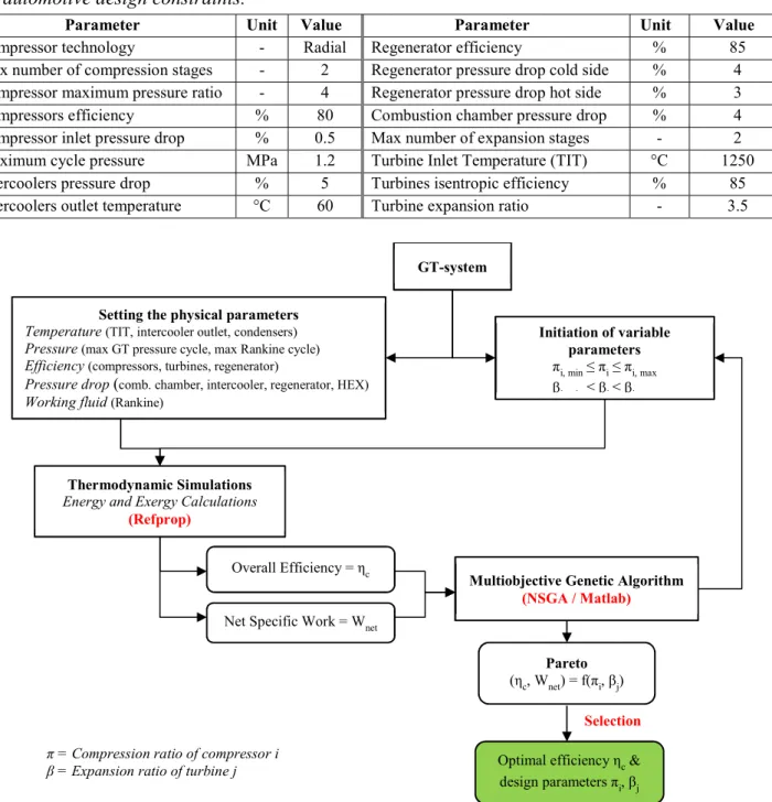
3.3.1 Components specifications ... 118
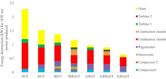
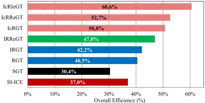
3.3.2 Thermodynamic optimization results ... 121
3.4 GT-system components design ... 124
3.4.1 Turbomachines ... 125
3.4.2 Heat Exchangers ... 126
3.4.3 Conclusions ... 130
3.5 Series Hybrid Electric vehicle model ... 133
3.5.1 Powertrain setup ... 134
3.5.2 Energy Management Strategy ... 134
3.6 Simulation results ... 137
3.7 Conclusion and perspectives ... 142
Annex 3.A : Simulation results ... 143
Chapter 4: Dynamic modelling of an Intercooled Regenerative Reheat Gas Turbine for auxiliary power unit on series hybrid electric vehicle ... 147
4.1 Introduction ... 149
4.2 IRReGT-System overview ... 152
4.3 Methodology ... 153
4.4 SHEV model ... 154
4.4.1 Powertrain setup ... 155
4.4.2 Energy Management Strategy ... 156
9
4.5 IRReGT dynamic modeling ... 159
4.5.1 Turbomachines ... 160
4.5.2 Heat Exchanger ... 162
4.5.3 Dynamic model results ... 164
4.6 IRReGT-SHEV Fuel consumption dynamic simulation results ... 170
4.7 Conclusions ... 174
Annex 4.1: fuel consumption results ... 176
Annex 4.2: Scenario 1 strategy ... 177
Annex 4.3: Scenario 2 strategy ... 178
Chapter 5: Experimental study on gas turbine subsystems: Evaluation of the turbine’s reheat process effect on the system performances ... 179
5.1 Test objectives ... 182
5.2 Theoretical power ... 184
5.3 Test bench description ... 187
5.3.1 Turbocharger description ... 191
5.4 Testing Method ... 193
5.5 Tests results ... 195
5.6 Conclusions ... 202
General Conclusion and perspectives ... 203
References ... 209
Annex 1: Evaluation of fuel availability ... 252
Annex 2: Exergo-technological explicit methodology for gas- turbine system optimization of series hybrid electric vehicles ... 260
Annex 3 : Assessing additional fuel consumption from cabin thermal comfort and auxiliary needs on the worldwide harmonized light vehicles test cycle ... 261
Annex 4 : Optimization of a Brayton external combustion gas-turbine system for extended range electric vehicles ... 262
Annex 5 : Fuel consumption saving potential of Stirling machine on series parallel hybrid electric vehicle : Case of the Toyota Prius ... 263
Annex 6 : Brayton cycles as waste heat recovery systems on series hybrid electric vehicles ... 264
Annex 7 : Exergo-technological explicit selection methodology for vapor cycle systems optimization for series hybrid electric vehicles ... 265
10
Annex 9: Internal combustion engine with high pressure isothermal compression of an intake air flow ... 267 Annex 10: Internal combustion engine with high pressure isothermal compression of an intake air flow ... 268 Annex 11: Regenerative Reheat Stirling machine ... 269 Annex 12: Innovative thermoacoustic machine for range extender vehicle application ... 270 Annex 13: External combustion Ericsson Split Cycle Engine for Powertrain
Automotive Applications ... 271 Annex 14: External combustion Ericsson Split Cycle Engine for Powertrain
Automotive Applications ... 272 Annex 15: Innovative Combined Cycle Gas Turbine System for Extended Range Hybrid Electric Vehicles ... 273
11
General introduction
Road transportation sector is amongst the fast-growing consumers of world oil and a source of greenhouse gas emissions, the most pressing factors of the current global environmental problems. Governments around the world are implementing policies to reduce oil consumption, climate-related emissions, and local air pollution. Several solutions have been offered by car manufacturers and stakeholders to reduce the environmental impact of road transportation. Today, the Internal Combustion Engines (ICEs) continue to play an important role as a power source for automobiles and is expected to keep its leadership as a primary converter for many years to come. However, the ICE, compatible with conventional fuels such as gasoline, natural gas and gasoil, generates non-negligible amounts of carbon dioxide (CO2) and is partly responsible of these greenhouse gas emissions. Therefore, according to an amended regulation, the average CO2 fleet emissions for particular cars in Europe must be reduced to 95 g CO2/km by the end of 2020 and to an indicative target range of around 70 g CO2/km in 2025; which means an approximate 50 % reduction in comparison to the 2015 target value of 130 g CO2/km. These numbers highlight the pressure on the automotive industry to innovate and push technological measures within every new vehicle to achieve these challenging targets; otherwise, high penalty payments are applied. Along with the introduction of such new targets, homologation procedures are either updated or created in order to reflect the vehicle usage in real life and avoid discrepancies between homologated values and what the driver is seeing in terms of fuel consumption, improving then realistically the air quality in the cities.
To reach these ambitious regulations targets, with the introduction of EURO6c regulation, associated to Worldwide Harmonized Light Vehicles Test cycle (WLTC) and Read Drive Emission (RDE) cycles, it is necessary to look for new technologies and powertrain innovations. A CO2 emission reduction can be achieved by either improving the power train efficiency of the energy conversion and/or by reducing the vehicle energy demands. Beside the development of hybrid electric vehicles (HEV) or plug-in hybrid vehicles (PHEV), innovations in the ICEs are essential to maximize the overall efficiency of the powertrains. Therefore, several technologies were identified during the period up to 2020, including innovation in combustion, engine architecture, thermal management, ICE component electrifications, ICE waste heat recovery systems, among others.
However, while these technologies allow to achieve the desired reduction in CO2 emissions, the potential of gain for after 2025, where the regulation will be more severe, is difficult to reach. In fact, the potential of the fuel efficiency gain is limited by the maximum theoretical efficiency of the ICE thermodynamic cycle performed. The ICE itself presents exergetic losses and its efficiency remains far from ideal engine efficiency, the Carnot engine. Also, adding these technologies to gain few efficiency points is at the expense of a cost that is becoming significant, which opens the opportunity for other energy converters to act as a replacement for the ICE.
12
Another key point to consider when using the ICE as primary converter, is its compatibility with different fuel types. ICE is compatible with conventional fuel, and the development of new energy vectors such as solid fuels, amoniac, or bio-fuels may jeopardize the operation of this machine.
Similarly, the homologation tests aim to reproduce the real vehicle consumption and emission and try to represent the driving mode. However, these cycles do not take into account the additional fuel consumption needed to ensure the thermal needs, (heating and cooling the vehicle cabin) which, under certain ambient conditions, could seriously impact the customer's consumption.
In addition, battery electric vehicle (BEV) promotion efforts across the world are increasingly diverse, with many governments and automakers pushing to promote awareness and sales of advanced electric-drive vehicles, as well as the necessary regulatory, charging infrastructure, and financial support. However, well-to-wheel CO2 emissions of a BEV is not advantageous mainly in markets where the electricity production relies on dirty fossil fuels.
In this context, and in order to meet the future CO2 requirements that are going to be set after 2025, PSA Groupe is investigating the potential of new energy converters, based on conventional thermodynamic cycles such as Stirling, Brayton, Gas Turbine, among others and not conventional machines such as fuel cells, thermoacoustic, thermoelectric generator, as primary energy converter in replacement of the ICE in automotive powertrain applications. Therefore, this thesis work aims at investigating the new potential energy converters that could replace the ICE, and targets at developing a methodology of choice and optimization of energy converters for automotive applications, while considering the energy converters compatibility with fuel and powertrain, the vehicle power needs to be included in the traction power, in the cabin heating and cooling power and in the electric auxiliary power, as well as in vehicle integration constraints such as weight and size. This scientific approach for the automotive industry requires taking into account technological constraints such as materials, maximum temperatures, maximum pressures, and automotive constraints such as mass, volume, power density, noise, price among others. Therefore, a methodology for choice and optimization of energy converters for automotive applications is required.
Chapter 1 of this work is a review for the different energy converters for automotive powertrain applications. The different energy converters are classified as internal combustion machines, external combustion machines or electro-chemical machines. Then a literature review and performance assessment is realized for each energy converter and the state of the art of each energy converter in automotive powertrain application is presented. The advantages and disadvantages of each energy converter compared to the reference internal combustion engine are presented. The chapter ends up by a synthesis in which a classification of the different energy converters in term of powertrain compatibility, fuel compatibility among other criteria is done. This synthesis highlights the advantages and disadvantages of energy converters other than piston engines for the automotive sector. It also helps understand the technological barriers
13
that must be removed in order to improve the efficiency and the performance of these converters.
Based on this synthesis, the gas turbine energy converter is selected among the potential energy converters for future electrified powertrains. It presents many vehicle intrinsic benefits such as multi-fuel capability, compactness, reduced weight, cogeneration capability, reduced number of moving parts compared to the reference internal combustion engine. Therefore, this energy converter has been selected for the rest of the study.
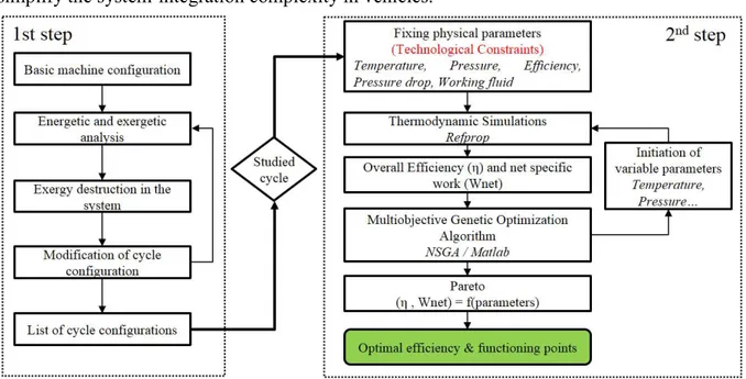
In chapter 2, the overall methodology for selecting the best suited thermodynamic configuration of the gas turbine cycle and its optimization for a series hybrid electric vehicle is presented. An exergo-technological explicit selection method, based on exergy analysis and optimization under technological constraints is applied and the intercooled regenerative reheat gas turbine (IRReGT) thermodynamic configuration is prioritized among others identified through the methodology. The optimization main criterion was the thermodynamic efficiency which impacts directly the fuel consumption. A series hybrid electric vehicle model is developed and the identified gas turbine cycle is coupled to an electric generator and integrated as auxiliary power unit (APU) to recharge the battery of the vehicle once depleted. A methodology for accounting for the additional vehicle non-mechanical energetic needs on the WLTC is presented. Fuel consumption simulations were then performed on this modified WLTC using the dynamic programing global optimal control strategy. Results are compared to the same vehicle equipped by an ICE-APU.
Since the weight of the system impacts the vehicle energetic demands and consequently the fuel consumption, a pre-design of the different realistic gas turbine system identified is performed in chapter 3. Based on the thermodynamic optimization of efficiency and net specific work, the power to weight ratio of each gas turbine identified configuration is calculated by accounting for the weight of the different components that constitute the system. Then each GT-system is integrated in the SHEV vehicle developed in chapter 2 and simulations are performed using a bi-level optimization method to find the optimal operating parameters in terms of system net output power and the number of times the ON/OFF switch of the APU is toggled on the pareto curve.
In order to account for the fuel consumption penalty when considering the transient operation of the IRReGT system, a dynamic model of the IRReGT was developed in chapter 4. The model considers both the turbomachines and the heat exchangers dynamic behavior. A dynamic mechanical model was developed for the turbomachines including the compressors and the turbines. Moreover, a dynamic model was also developed for the regenerator heat exchanger. Simulations are performed while considering two different gas turbine startup strategies and the additional fuel consumption were compared to results found in chapter 3.
Finally, in chapter 5, different subsystems of the IRReGT system were tested. In this manuscript, only the turbine reheat subsystem was presented. Tests results were compared to the simulation theoretical results. The importance of the the turbine reheat process is then checked and confirmed.
14
15
Résumé chapitre 1
L'électrification des groupes motopropulseurs représente aujourd'hui la solution pour les constructeurs automobiles pour respecter les réglementations strictes imposées en matière de consommation et d'émissions de polluants, et de maintenir une autonomie comparable à celle des véhicules à chaîne de traction conventionnelle. La consommation de carburant de ces groupes motopropulseurs dépend en grande partie du rendement des convertisseurs d'énergie et de la stratégie de gestion de l'énergie déployée à bord. Une revue de la littérature montre une diminution des activités de développement sur les moteurs à combustion interne (ICE) comme convertisseur d'énergie primaire pour les véhicules. D'une part, ces convertisseurs présentent très peu de marge d'amélioration supplémentaire du rendement en raison des pertes d'énergie associées au cycle thermodynamique effectué, et d'autre part, ils n'ont pas la capacité d'utiliser plusieurs carburants, ce qui limite leur fonctionnement principalement aux combustibles liquides tels que l'essence et le diesel. Dans ce contexte, et afin de répondre aux exigences en matière de CO2 pour l'après 2025, il est important d'étudier la possibilité de remplacer les moteurs à combustion interne par de nouveaux types de convertisseurs d'énergie. Ce chapitre présente une revue des différents convertisseurs d'énergie thermodynamique et thermochimique pour les applications automobiles. Une étude bibliographique est d'abord effectuée pour chacun des convertisseurs d'énergie étudiés afin d'identifier les meilleures pratiques d'utilisation de ces convertisseurs dans les applications automobiles. Ensuite, une analyse est effectuée afin de comprendre le principe de fonctionnement de ces convertisseurs ainsi que d'identifier les paramètres de conception clés. Une évaluation technique des indicateurs clés de performance des convertisseurs est effectuée à l'aide de critères de performance quantitatifs et qualitatifs. Les critères quantitatifs évalués sont le rendement, le travail spécifique net, le rapport poids/puissance et le rapport taille/puissance, et les critères qualitatifs évalués sont la fiabilité, les aspects de maintenance, l'impact environnemental, le bruit et la maturité technologique dans les applications automobiles et autres applications industrielles. Enfin, les convertisseurs d'énergie sont classés en fonction de leur attractivité pour les constructeurs automobiles dans l'intégration dans de nouvelles architectures de groupes motopropulseurs électrifiés et de leur potentiel de développement pour atteindre les objectifs de consommation et d'émissions après 2025.
17
Chapter 1: A review on energy converters for automotive
powertrain applications
1.1 Introduction
Various machines are dedicated to the conversion of fuel into mechanical or electrical energy. They are classified in the automotive applications under three different categories:
1. Internal combustion machines, such as internal combustion engines (ICEs), split cycle engines (SCE) and Gas Turbine systems (GT).
2. External combustion machines, such as Brayton or external combustion gas turbine (ECGT), Stirling, Vapor Cycle machines (VCM), Ericsson, Thermoacoustic (TA) and Thermo-electric generators (TEG).
3. Electrochemical energy converters such as fuel cell (FC) which exists in different types: Proton Exchange Membrane Fuel Cells (PEMFCs), Direct Methanol Fuel Cells (DMFCs), Solid Oxide Fuel Cells (SOFCs), Alkaline Fuel Cells (AFCs), Phosphoric Acid Fuel Cells (PAFCs) and the Molten Carbonate Fuel Cells (MCFCs).
Some of these machines have been commercialized at the beginning of the late century as vehicle prime movers. Among these machines the VCM, where production continued to the 1930’s on steam cars [VM1, VM2]. Other machines have been also largely investigated as main energy converter instead of conventional piston ICE in automotive application. We can list for example: the gas turbine system [GT1], the Stirling machine [ST1-ST9], and recently the fuel cell [FC1-FC7].
18
1.2 ICE: the dominant prime mover in automotive powertrain
applications
Nowadays, the ICE, which pioneered for more than decades the automotive industry by being the widely used prime mover, is still undergoing plenty of research and engineering developments in order to improve its performance at all levels. The recent turbocharged ICE presents high specific power, high power to weight ratio and high power to size ratio. Recently, turbocharged engines are the technology of choice in vehicles, due to their good efficiency, fast time response, affordable cost, as well as availability of production and logistic processes. These engines continue to play an important role as a prime mover for automobiles and are expected to keep their leadership as a primary converter where around 88% of vehicles are expected to be equipped with an ICE on the near to medium terms [IC1-IC3].
Fig.1.2: Automotive engine power (kW) function of engine’s weight (kg) and size (L)
Fig.1.3: Automotive engine power (kW) function of engine’s weight (kg) and displacement (L) 183 107 184 173 178 239 214 118 67 306 191 93 116 0 50 100 150 200 250 300 350 400 0 100 200 300 400 500 600 700 800 E ng in e w ei gh t ( kg ) Engine size (L) 183 184 239 214 67 306 191 93 116 0 50 100 150 200 250 300 350 400 0 1 2 3 4 5 6 E ng in e w ei gh t ( kg ) Engine displacement (L)
19
1.2.1 Regulating the GHG emissions from vehicles
Meanwhile, governments from around the world are implementing policies to reduce fuel consumption and climate-related emissions, as well as to improve air quality in urban areas. For instance, the European Union (EU) adopted a roadmap for reducing greenhouse gas emissions from the transportation sector by 60% in 2050 compared to emission levels of 1990 [IC4, IC5]. Therefore, the automotive industry needs to bundle their full innovation potential and stringently work for the achievement of the upcoming legislative requirements.
Accordingly, the market of electric vehicle (EV) is expanding, due to the benefit of zero CO2 and pollutant tank-to-wheel emissions from these vehicles. However, EVs still suffer from mileage limitation, expensive battery cost, additional battery weight and limited charging infrastructure. In addition, the well-to-wheel CO2 emissions of an EV can be as poor as that of conventional vehicles in countries with dirty electricity generation mixes [IC6].
Therefore, regulating the CO2 emissions for the whole fleet of new passenger cars (PCs) is a key instrument to reduce emissions from road traffic. For instance, according to a recently amended regulation, the average CO2 fleet emissions for passenger cars (PCs) in Europe must be reduced to 95 g CO2/km by the end of 2020 and to around 70 g CO2/km in 2025 [IC7]. These numbers highlight the pressure on the automotive industry to innovate and push technological measures within every new vehicle to achieve these challenging targets, otherwise, penalty payments are applied [IC8].
Fig.1.4: CO2 emissions regulations in the world [IC7]
With the recent introduction of new regulations test procedures such as the WLTP and the RDE cycles [IC9] in order to reflect the vehicle under real driving conditions, it is necessary to look for the development of new generations of ICE and advanced powertrains. In fact, CO2 emission reduction can be achieved by either improving the powertrain efficiency or by reducing the vehicle energy demands. Research and development targets from the literature
20
shows that several technologies are identified to increase powertrain efficiency until 2025 [IC10], such as:
Engine architecture: friction reduction [IC11, IC12], lubricating system [IC13, IC14], variable compression ratio and variable displacement [IC15-IC17], engine downsizing [IC18, IC19]
Combustion: innovative combustion and downsizing [IC20, IC21], variable valve train [IC20], Cylinder Deactivation [IC21-IC23], homogenous charge compression ignition [IC24, IC25].
Electrification of drive train and auxiliary consumers, as well as working on transmission, driving resistance and waste heat recovery (WHR) systems.
Thermodynamic advanced cycles: Atkinson-Miller thermodynamic Cycles [IC26], Turbocharging [IC20, IC27]
Thermal management [IC28],
Hybrid powertrains including [IC29, IC30]
Electrification of auxiliary consumers [IC31-IC33]
New driving systems such as CVT and dual clutch transmission [IC34, IC35]
On the other hand, reducing the vehicle energy demand is done by improving the driving resistances, such as reducing the tires rolling-resistance and the vehicle aerodynamic, embedding lightweight materials in the chassis and components as well as optimizing the thermal energy needs for passengers’ comfort. Current used thermal comfort technologies could dramatically increase the vehicle consumption under certain weather conditions [IC36].
1.2.2 ICE’s fuel consumption savings potential
However, despite these innovations and technological developments on ICE, the potential of fuel consumption savings of ICE based powertrain is limited by the maximum theoretical efficiency of its thermodynamic cycle. The machine itself presents exergy losses [IC37, ICE38] and its efficiency is far from Carnot maximum theoretical efficiency. Therefore, the ICE has been the target of much controversy in regard to both its potential improvement and its possible replacement. While some significant increase in efficiency and pollutants reductions have recently been achieved by costly and complex technologies, substantial further improvements will be very difficult to attain. Today, it seems rather improbable that higher efficiency and acceptable pollution levels can ever be attained without a great deal of mechanical complexity and cost penalties. This matter is serious enough to interest automotive constructers in alternative propulsion systems.
Another disadvantage for the use of ICE as the vehicle prime mover, is its lack of use of multi-fuel, which limits it operation to some fuels, mainly liquid fuels such as gasoline and diesel [IC39]. Therefore, ICE cannot make any advantageous use from the new solid fuel energy vector that is gaining recent interest in the automotive industry.
21
Fig.1.5: Illustration of the powertrain efficiency versus cost/complexity for ICE and other energy converters
1.3 Investigation of the potential use of new energy converters
In this context, and in order to meet the post 2025 CO2 requirements under the ongoing trend of hybrid electric powertrains development, it is important to investigate the potential applicability of new energy converters as a substitute to ICEs. This imposes on these new energy converters to meet the basic requirements imposed on prime movers in vehicle. Among these requirements, we can list: fuel efficient operation over a duty cycle, competitive manufacturing, affordable initial and life cycle cost, fast acceleration and time response, compatibility with new powertrains, reduced emission and noise levels, acceptable reliability and safety, acceptable volume and weight, cogeneration and multi-fuel capability.
Fig.1.6: Automotive requirements for new energy converters
Energy converter Efficiency Weight Compacity Emissions Multi-fuel Cogeneraion Cost NVH Technology master
22
1.3.1 Research questions
The study of the literature shows that there have been many attempts in the past to replace the ICE by these energy converters. We can mention, Chrysler, Volkswagen, Fiat and Citroën studies on gas turbines [GT1-GT4], GM, Opel and Ford investigations on Stirling machines [ST1-ST7], and GM studies on steam vapor cycles [VM3]. So what were the obstacles against commercialization in series production cars? Similarly, other industries have much more efficient attractive machines such as the combined cycle gas turbine (CCGT) systems for power generation where efficiency can reach more than 60% on specific operating points compared to a maximum around 40% for ICE piston engines. What are the technological problematics that prevent their use in small scales in automotive vehicles?
Today, split cycle engines (SCE) offer high efficiency and good power density, with the advantage of many components and functional synergies with actual ICE. Also, The GT has very favorable specific power and energy efficiency characteristics and presents a forthcoming potential for improving modern vehicle efficiency and emissions with the benefit of fuel-use flexibility when compared to ICEVs. Furthermore, with the development of series hybrid architectures, which combines a thermal and an electric powertrain in a series energy flow arrangement, the GT operating point is easily controllable to operate on the best efficiency. On the other hand, external-combustion (EC) engines have received much recent attention because of their very low pollution characteristics among them, Stirling and Ericsson engines. Besides their very low pollution level, these engines are very quiet and have multi-fuel capability and good efficiency. Also the external combustion steam Vapor Cycle machines engine has, despite its limited efficiency, high specific power, and a multi-fuel capability. Finally, the Fuel cell systems today offer high efficiency despite the fact that they have limited specific power. In order to highlight the advantages and drawbacks of different energy converters for vehicle powertrains, and to respond to the interrogated questions above, this chapter presents an overview on different energy converters as prime movers for automotive applications.
1.3.2 Review approach adopted in the manuscript
The approach adopted in this study is presented in figure 1.7 below. A bibliographical study is conducted first for each of the investigated energy converters in order to identify the best practices of use of these converters in automotive applications. Then, a design analysis is performed in order to understand the operating principle of the energy converter as well as the key design points and parameters is performed. The third step consists of a technical assessment of these converters, using quantitative and qualitative performance criteria. Among the quantitative criteria, we can mention the efficiency, the net specific work, the weight to power ratio and the size to power ratio. Among the qualitative criteria, the reliability, the maintenance aspects, the environmental impact, the noise and the technology master in automotive and no automotive industry are stand out. Finally, results are synthesized while considering the fuel use capability, the powertrain configuration compatibility including conventional, parallel hybrid and series hybrid as well as other automotive criteria and technical recommendation are proposed.
23
Fig.1.7: Approach of the study
Table 1.1: Internal Combustion Engine (ICE) for automotive powertrain applications
Characteristics Value and Description
Efficiency range 35 to 38% (Gasoline engines) 38 to 42% (Diesel engines) Power to weight ratio 400-600 W/kg (atmospheric) 800-1200 W/kg turbocharger Power to size ratio 300 – 750 W/L
Fuel Liquid and gaseous conventional fuels (Gasoline, Gasoil, Ethanol, Natural gas…) Combustion process Internal Combustion
Working fluid Air
Emissions Norm Euro 6 after-treatment emissions
Complexity/size Moderate to high complexity integration - acceptable size NVH Moderate noise and vibration aspects
Controllability Mastered controllability aspect Maintainability Good maintainability
Reliability High reliability – validated for more than 180.000 km driving distance
Safety High safety level
Powertrain compatibility All powertrain architectures
Cogeneration capability Ensure hot thermal need for vehicle cabin heating
24
1.4 Internal combustion engines
1.4.1 Split Cycle Engine
1.4.1.1 Literature review and performance assessment
The Split Cycle Engine (SCE) is an internal combustion engine based on the piston-connecting rod architecture where the intake and compression strokes are performed in one cylinder and the power/expansion and exhaust strokes in a second cylinder, as illustrated in figure 1.8. The compression and power cylinders are connected through a cross over passage that transport the compressed air into the power cylinder.
The SCE operates similar to two-stroke engines. It produces one power stroke for every revolution of the crankshaft. Therefore, the net power-to-weight ratio and the net power-to-size ratio are comparable to actual ICE [SC2].
Splitting between the engine strokes offers advantageous design flexibility compared to conventional ICE [SC3]. In fact, one of the advantages of performing the compression and the expansion in two different cylinders, is the possibility of increasing the power stroke cylinder volume and downsizing the compression cylinder [SC4], performing therefore more easily the Miller thermodynamic cycle. This concept offers also the advantage of optimizing the thermal management of each cylinder: A cooler compression to reduce the compression work and a hotter expansion to maximize the expansion work [SC5, SC6]. Note also the possibility to adapt the kinematic motion of each piston and the displacement as for an Atkinson ICE.
The thermodynamic operation of this concept is based on the Ericsson cycle when the compression and expansion strokes are isothermal, and it is based on the Joule thermodynamic cycle when these strokes are adiabatic, which makes the SCE gain advantage in terms of efficiency when compared to Otto, Diesel, Dual or Atkinson-Miller thermodynamic cycles actually performed on piston ICE.
Fig.1.8: Split cycle engine concept [SCE1] Fig.1.9: Turbocharged Scuderi SCE concept with air storage tank [SCE23]
25
The split cycle concept preceded the Otto and Diesel engines, and dates back to 1891 when it was invented and produced for the first time by Backus Water Motor Company [SC7].
The power range of the first produced engines varied between 1/2 and 3 horsepower, with potential power increase up to 25 horsepower [SC8]. Several studies trace further developments on this concept back to 1910 [SC9], where different architectures and thermodynamic configurations were investigated [SC10-SC12].
Despite the several advantages of the SCE, the review of the literature attributed some drawbacks to this concept. Patil et al. [SC1] highlighted the poor SCE breathing as compared to the ICE, caused by the high-pressure gas trapped in the compression cylinder, which should have been re-expanded before another intake stroke occurs in the compression cylinder. This drawback leads to poor volumetric efficiency, which reduces the engine’s capacity to pump air and presents potential work losses. Another drawback underlined by the authors is the low thermal efficiency of the SCE caused by firing the air fuel mixture before the piston reaches its top dead center. In fact, when the compressed air trapped in the crossover passage expands into the power cylinder while the power piston is in its upward stroke, the work done on the air in the compression cylinder is lost, and the engine performs the compression work twice leading to low thermal efficiency [SC1].
Additional technical difficulties must be addressed while operating the SCE. Scuderi company [SC13] showed that the valves timing has to be adapted for each engine operating point in order to maximize the corresponding volumetric efficiency. Scuderi reported that the cylinder head, the liner and the expansion piston temperatures have to be controlled in order to avoid the breakdown of the lubricating oil film and the risk of thermo-mechanical failure of these components. In fact, the cold air during the intake stroke never enters into the power cylinder to cool it down, as the case in conventional ICE; consequently, the average temperature in the power cylinder exceeds the melting temperature of the components material, in particular the cylinder head if made out of aluminum.
In addition to the mentioned control difficulties, extensive validation test procedures are required to ensure the reliability of SCE, since it was not fairly explored in commercial application yet. Therefore, the literature presents gaps in terms of information on the maintenance routine and the reliability of this machine.
1.4.1.2 State-of-the-art of split cycle engines in automotive powertrain applications Although the SCE was not sufficiently explored in commercial applications, numerous studies have proposed the SCE as a substitute to the conventional ICE in automotive powertrain applications.
The Scuderi Group has extensively explored the use of SCE in powertrains. It presented in [SC1, SC14-SC16] an SCE model with high compression ratio ranging between 75:1 and 100:1. Gaikwad et al. present in [SC17] a detailed description of the operation and the thermodynamic processes of the Scuderi SCE. Several advancements are made to the proposed model compared to the theoretical SCE thermodynamic cycle presented in the previous section, such as firing
26
the air-fuel mixture after the top dead center, improving the design of the crossover passage valve, and increasing the turbulence in the power cylinder. These advancements resulted in an enhanced volumetric efficiency and thermal efficiency of the engine.
Numeral studies were later presented in the literature assessing the performance of the Scuderi SCE using CFD modeling and simulation. Patil et al. [SC1] compared the performance between a Scuderi SCE and a conventional spark ignition ICE of approximately same volume and for same amount of charge. The Scuderi SCE showed 5% improved indicative thermal efficiency and higher torque at low engine speed, which provided the SCE, 15 to 20% additional power compared to the reference conventional SI engine [SC1]. Scuderi Group explained in their patent [SC14] that the compression and expansion ratios, the top-dead-center pistons phasing, the crossover valve duration and the combustion duration are the key variables affecting the SCE performance and efficiency. Moreover, Scuderi revealed in later publications on methods to improve the part load efficiency of SCE [SC18, SC19]. Other such as Lam et al. proposed also in their study [SC20] a double compression expansion engine concept in order to further improve the SCE efficiency and its net specific power.
Scuderi in [SC21-SC25] also investigated other SCE configurations, namely an air hybrid SCE concept and a Miller turbocharged SCE cycle with air storage tank, illustrated in figure 1.9. SwRI simulations show in [SC26] that the Scuderi SCE consumes 25% less fuel than a comparable conventional ICE, and up to 36% with the hybrid configuration. The turbocharged SCE configuration allows decreasing the brake specific fuel consumption by 14% and increasing the brake mean effective pressure by 140% compared to the regular Scuderi SCE. In that case, the engine has been downsized by 29% thanks to adding a turbocharger, and it was capable of delivering a specific power of 135 hp/liter at 6,000 rpm. In addition to the consumption and performance improvements, the Scuderi SCE concept proved in [SC27] to reduce the NOx emissions by 80% as compared to an equivalent conventional ICE.
Dong et al. performed a thermodynamic analysis on split cycle with internal heat exchanger recuperator to recover the waste heat at the outlet of the expansion cylinder [SC28]. The authors propose a method to decrease the compression work through the injection of a controlled quantity of water in the compression cylinder, lowering therefore the gas temperature during compression. The detailed cycle simulation indicates up to 32% efficiency improvement compared to conventional diesel engine.
Several studies in the literature investigated the combustion process of SCE. Cameron et al. showed in their study [SC29] that the main combustion duration is very rapid for all tested conditions despite the late combustion phasing. This has the advantage of reducing the NOx during rapid expansion as well as reducing the detonation tendency compared to conventional spark ignition controlled combustion [SC22]. Caterpillar showed that Diesel SCE could be favorable to control diesel HCCI combustion and to limit the NOx emissions [SC30, SC31]. Tour Engine is developing an opposed split cycle engine [SC32-SC35], by coupling the two opposing cylinders of two GVX50 Honda engines with a single crossover valve which allows minimal dead space and superior thermal management. Motiv Engines presents similar SCE
27
configuration in [SC36], where 20% increase in efficiency are announced as compared to modern diesel engines. The engine achieves a high compression ratio of 56:1 leading to 30 MPa peak pressure.
Despite the numerous presented concepts of SCE, none reached the mass-production phase yet on passenger cars. The only commercially available SCE is the Ricardo split cycle isothermal compression engine with water injection and internal heat recovery developed with RWE Innogy [SC37-SC39], illustrated in figure 1.10. This model is available with a wide power range between 1 MW and 30 MW, it uses water injection during the compression stroke to achieve isothermal compression and higher efficiency of around 56%. It is currently mainly dedicated for heavy-duty applications, marine applications and power generation. An improved version of this model was presented in [SC5], substituting the water injection during compression by liquid nitrogen. A pilot simulation of this concept has predicted a thermal efficiency of 60% [SC6, SC40].
Fig.1.10: Ricardo split cycle isothermal compression engine with water injection and internal heat recovery. [SC38]
1.4.1.3 Synthesis on split cycle engine
Due to the high efficiency and the expertise of manufacturing piston reciprocating engines in the automotive industry, the SCE presents a potential energy converter for the next generation powertrains in order to meet the future CO2 and emissions regulation targets. This piston-cylinder-based machine offers higher efficiency, lower emissions and comparable power density to the conventional ICE. Moreover, it is compatible with liquid and gas fuels, and adaptable to conventional and electrified powertrains. In addition, alike ICE, the SCE is a cogeneration machine capable of covering the cabin thermal needs through the engine cooling system. Therefore, this type of piston-based engine with quasi-identical conventional architecture can limit the investment costs while relying on the acquired expertise for the engine development and validation. However, some technical issues such as the material resistance in the power cylinder and the valves controllability as well as additional validation tests under variable load driving conditions have to be overcame in order to ensure the machine’s
28
reliability. Table 1.2 summarizes the advantages and drawback of SCE observed in the literature and table 1.3 synthesized the performance assessment.
Table 1.2. Advantages and drawbacks of the split cycle engine.
Advantages Engine design flexibility
Compatibility with existing engine equipment namely turbochargers and waste heat recovery systems
Higher torque at low engine speed and higher power performance compared to the basic ICE architecture
Higher volumetric, thermal and overall efficiencies Reduced piston-cylinder friction by offsetting the cylinders NOx emission reduction
Compatibility with all ICE fuels
Drawbacks Still under research investigation, none of the powertrain applications reached the mass production level yet
May require expansive material compared to conventional four stroke ICE, in order to resist to the high temperature in the power cylinder
Require valve controllability for different operating points
More expensive than conventional ICE due to the higher number of cylinders since two cylinders are required to complete the four strokes
May increases the engine cost
Table 1.3. Summary of split cycle engine performance criteria.
Characteristics Value and Description
Efficiency range
40 – 43% without regenerator [SC1]
Up to 45% with regenerator and more than 50% with regenerator and isothermal compression [SC38, SC41]
Net specific power similar performance compared to ICE or 20% higher [SC26] Power to weight ratio 250 – 900 W/kg(*)
Power to size ratio 275 – 650 W/L(*)
Fuel Same as ICE fuels
Combustion process Internal Combustion
Working fluid Air
Emissions Reduced emissions compared to ICE [SC27]
Complexity/size Moderate to high complexity integration, comparable to ICE size Noise and vibration Moderate noise and vibration aspects
Controllability Complex controllability for transient operation Maintainability Still under investigation
Reliability Still under investigation
Safety High safety level – same architecture components such ICE
Powertrain compatibility Compatible with conventional and electrified powertrain architectures Cogeneration capability Ensure hot thermal need for vehicle cabin heating
Technical maturity Medium technical maturity in automotive industry, still in R&D phase *Based on ICE data and considering the additional weight and volume of components such as crossover and regenerator heat exchanger
29
1.4.2 Gas turbine
1.4.2.1 Literature review and performance assessment
Gas turbine (GT) energy converters are thermodynamic turbomachines that convert the thermal energy of the working fluid into useful mechanical energy, and generate torque on the turbine shaft.
The simple GT configuration operates according to the Brayton cycle [GT5], as illustrated in figure 1.11. It is composed of an upstream compressor coupled to a downstream turbine. The compressor increases the air pressure, before heat is added, either internally through a combustion chamber or externally through a heat exchanger in the case of an externally fired gas turbine [GT6]. The high temperature pressurized gases then expand in the turbine and produce a mechanical work that could be used in multipurpose operations, namely driving an electric generator to produce electricity [GT7, GT8], or propelling a blade for marine transportation [GT9, GT10], or producing thrust in aeronautical applications [GT11], or propelling a vehicle [GT1, GT12]. Gas turbine cycle can also be of open cycle type or closed cycle type. The open cycle internal combustion is the most common one, in which the combustion products are rejected to the ambient surrounding, whereas the closed cycle uses a heat exchanger to reject the heat to the ambient surrounding [GT13].
Fig.1.11: Simple Gas Turbine system configuration.
John Barber patented the first turbine system configuration in 1791 [GT14]. In 1903, Aegidus Elling built the first successful simple gas turbine system, using a six-stage radial compressor and a single-stage radial turbine, with a maximum turbine inlet temperature (TIT) of 400°C and a net output power of 8 kW [GT15, GT16]. In 1905, Stolze [GT17] installed the first ten axial compressor stages and fifteen axial turbine stages GT at Berlin-Weissensee power station [GT18, GT19]. His machine delivered a net power output of approximately 150 kW. During the same year, Hans Holzwart [GT20] introduced the constant-volume combustion chamber turbine. In 1906, Charles Lemale and Rene Armengaud developed a 400 horsepower GT designed by August Rateau with twenty-five stage centrifugal compressor, an intercooler and two-stage impulse design axial turbine [GT14]. The world first successfully commercial GT
30
system generating electric power was developed by BBC, and went into market first in Switzerland [GT21]. This GT system consisted of twenty-three stage axial compressor and a seven-stage axial turbine. It reached a TIT of 550°C and a compression ratio of 4.4, and it delivered 4000 kW net mechanical power and achieved an overall efficiency of 17.4%, with compressor and turbine overall efficiency of 85% and 88% respectively.
Since early developments in the gas turbine technology, the struggle was to achieve higher cycle efficiencies. The design efficiency of GT is mainly controlled by the operating temperatures of the cycle and the efficiency of the components [GT22, GT23]. Therefore, considerable efforts were devoted to increase the TIT from 788°C in the 1960’s [GT24], to 1260°C in the 1990’s and up to more than 1650°C nowadays [GT25-GT33]. These improvements are based on the development of high strength materials, high temperature coatings and improved blade-cooling methods, blade designs and aerodynamics.
Numerous studies in the literature explore the developments made to the other constituting components of the GT system. Whittle, Cheshire and Eckardt et al. presented respectively in [GT19, GT34, GT35] the early developments made to the two main compressor types used in GT systems: (1) the axial flow compressor and (2) the centrifugal compressor. Each type is used in a different application depending on the required specifications such as the frontal area, the weight, the efficiency and the cost [GT36]. Alike the compressor, there are two basic types of turbines, the radial flow type and the axial flow type. The radial turbine is more compact and can handle efficiently low mass flow rates [GT8], but it is normally less efficient than the axial flow turbine [GT37]. Therefore, it is used as aircrafts auxiliary power units [GT38] and for supercharged ICE [GT39]. Cohen et al. and Nagpurwala set up in [GT8] and [GT40] the main requirements for the design of the combustion chamber: high combustion efficiency, high reliability, low costs and no visible smoke. Several studies highlighted the different techniques considered nowadays to cope with nitrogen oxides emissions from combustion chambers, such as using the water or steam injection technique [GT41, GT42], the selective catalytic reduction, the SCONOX catalytic absorption system or the dry low NOx (DLE) technology [GT8, GT43-GT45]. Reduction of pressure loss in combustion chambers [GT47-GT49] and heat exchangers namely the regenerator [GT50] was also a major concern tackled in the literature, as it strongly affects the GT system efficiency [GT51]. Recent heat exchangers effectiveness exceeds 90% with a pressure drop less than 5% [GT49]. Rotary ceramic-matrix regenerators achieve heat transfer effectiveness between 93% and 98% with leakage below 4.5% and pressure-drop per stream between 1.8% and 5.4% [GT52, GT53]. Pathiranthna, Nada and Shah et al. [GT54-GT56] highlighted other pressure drop concerns in the GT system, mainly at the compressor inlet and the turbine outlet.
Beside the developments made to the components and their material, advanced gas turbine thermodynamic cycles have been examined [GT50, GT52], and several GT-system thermodynamic configurations are explored in the literature, as summarized in table 1.4.
31
Table 1.4: Synthesis on the different GT-system configurations explored in the literature. GT system thermodynamic
configuration Insights
Combined GT cycle [GT58-GT64]
Combining a gas turbine cycle to steam Rankine cycle in order to achieve high efficiency and high power density.
GT with recuperator [GT7, GT65]
Increasing the efficiency by recovering thermal waste heat at turbine outlet at the expense of the net specific work
GT with intercooling
[GT65-GT69] Increasing the net specific work by reducing the compression work through an intercooled compression Reheat GT cycle
[GT19, GT70]
Increasing the net specific work by performing a turbine reheat cycle
Intercooled recuperated GT [GT22, GT71]
Increasing the cycle efficiency by increasing the net specific work and by recovering heat lost at turbine outlet
Intercooled recuperated reheat GT [GT11, GT72]
Increasing the cycle efficiency and the net specific work by both technics described above
Isothermal expansion GT [GT73]
High net specific work and efficiency by achieving an isothermal expansion through a combustion inside the turbine Steam Injected Gas Turbine cycle
(SIGT) [GT74-GT76]
Combined GT cycle where water is injected in various locations to increase the efficiency and the net specific work Chemically Recuperated Gas
Turbine (CRGT) [GT77-GT80]
Exhaust heat is recovered in a Heat Recovery Steam Generator (HRSG) in which the super-heater section is replaced by a Methane Steam Reformer (MSR)
Advanced Integrated Gasification Combined Cycle (IGCC) [GT81]
Use high pressure gasified to turn coal and other carbon based fuels into gas
Evaporative GT (EGT) [GT82], Humid Air Turbine (HAT) [GT83] and Cascaded Humidified Advanced Turbine (CHAT) [GT84]
Water is injected downstream the compressor (EGT) and at other locations (HAT, CHAT) in order to cool the air upstream the regenerator. The addition of water increases the turbine mass flow and power output, and reduces the temperature drop which increase the regenerator effectiveness
Gas turbine coupled to SOFC [GT85, GT86]
High efficiency (of more than 70%) can be achieved by combining the GT to the SOFC
1.4.2.2 State-of-the-art of gas turbine systems in automotive powertrain applications Many attempts to substitute the conventional ICE in passenger vehicles with GT are explored in the literature [GT8, GT17, GT87]. Chrysler presented in the 1950’s the first regenerative GT prime mover powertrain configuration [GT1], with radial compressor, illustrated in figure 1.12. Many improvements have followed in the subsequent generations of the concept, aiming mainly at improving the compressor and turbine efficiency, increasing the TIT and the regenerator effectiveness, development of new materials, variable geometry at the turbine nozzle and variable geometry compressor, water injection, material cost, leakage seals, production process. GM, Fiat and Volkswagen introduced in the 1950’s the GM Firebird prototype, the Fiat Turbina (200 hp GT [GT88]) and the SquareBack VW (75 hp GT [GT2]). Additional prototypes were developed for racing vehicles, such as the Rover-BRM [GT5] and the Lotus 600 hp GT Formula1 [GT-89]; and other prototypes for heavy trucks such as the Chevrolet Turbo Titan III [GT90] and the GMC Astro Gas Turbine truck [GT91].
All these GT vehicle models showed poor acceleration response and higher fuel consumption compared to internal combustion engine vehicles (ICEV). These drawbacks where mainly due
32
to operating the GT at high speed even at idle conditions, in addition to mechanically coupling the turbine to the vehicle driving load, which resulted in a low efficiency operating range of the GT-system. Despite the many technological advancements and improvements made on GTs, the acceleration lag and the poor fuel efficiency were still the main reasons hindering their deployment in conventional powertrains.
Fig.1.12: Chrysler regenerative gas turbine system for passenger vehicles [GT1]. A review of recent research and development programs of automotive manufacturers revealed new interests in GT for automotive applications, demonstrated in several vehicle concept cars. In 1995, Volvo presented its Environmental Concept Car (ECC) with GT as main energy converter, based on the Volvo 850 serial model [GT92]. In 1997, PSA investigated the GT on the Peugeot 406 with series hybrid electric powertrain architecture [GT4]. In 1998, GM introduced the EV-1 series hybrid vehicle that was adaptable to use either an ICE or a 40 kW GT as range extender driving a generator to recharge the batteries [GT93]. In 2006, GM presented the Ecojet Concept Car using a helicopter GT generating 650 hp maximum power and 790 Nm torque [GT3] and in 2009, Jaguar presented the C-X75 concept car that uses a pair of twin-shaft Capstone CTM-380 GT as range extender [GT94]. In the same year, ETV Motors investigated the potential of GT on a Toyota Prius, equipped with a micro GT, operating as a Range Extender [GT95]. In 2012, Pininfarina announces the development of a super Car equipped with a Diesel GT as a range extender [GT96]. The GT system is expected to extend the vehicle autonomy by 600 km, originally designed for 200 km all electric range. The vehicle will not require NOx after-treatment system since emissions will not exceed 0.05 g/km, which makes the vehicle pass the Euro 6 standards. Similar conclusion was derived by a study at the University of Rome, showing that GT emissions at optimal efficiency operation meet the Euro 6 emissions levels for CO, NOx and soot without the use of after-treatment systems [GT97]. TechRules announced the development of similar series-hybrid range-extender powertrain configuration for its high performance sports car [GT98], using a 96,000 RPM turbine mounted on air bearings with pneumatic positioning. The vehicle autonomy is expected to reach 1850 km with an average consumption of 4.8 L/100 km. The main drive behind developing series-hybrid range-extender configurations by all manufacturer for their GT systems was explained
33
by a study at Chalmers University of Technology, which highlighted the improved efficiency by operating GT at optimal efficiency point compared to an ICE [GT12], in addition to all the benefits derived from using an electric machine for the propulsion.
GT applications were also observed in heavy-duty prototypes. Volvo developed in 1990’s both the Environmental Concept Truck (ECT) and the Environmental Concept Bus (ECB), two prototypes with hybrid propulsion system coupled to GT [GT99]. Wrightspeed unveiled the Fulcrum GT, a 80 kW two-stage compression regenerative GT [GT100], with a power to weight ratio of 750W/kg. It operates as range extender on electric powertrain truck. Walmart showcased the Walmart Advanced Vehicle Experience (WAVE), a range extender series hybrid tractor-trailer prototype, with a multi fuel capability Capstone GT [GT101].
Fig.1.13: GT net power as function of the GT system weight for different GTs. 1.4.2.3 Synthesis on gas turbine systems
Different manufacturers explored the potential integration of GT in conventional powertrains since the 50’s as a substitute to the ICE. The poor vehicle acceleration response and the high fuel consumption compared to ICE vehicles were among the main drawbacks, which prevented their commercialization.
Recent literature reflected a revived interest in GT application, in particular on series-hybrid electric vehicles, which combine the GT to an electric powertrain in a series energy-flow arrangement. Since the GT operation is cinematically decoupled from the vehicle speed, the operating point is easily controllable to run on the GT best efficiency point, which enhance the overall vehicle efficiency. The GT-system offers in addition other intrinsic benefits for vehicle powertrains such as the reduced number of moving parts, the vibration-free operation, the high durability and the absence of cooling and emissions after-treatment systems. All these benefits combined makes the GT a forthcoming potential for improving modern vehicle efficiency and emissions, with the benefit of fuel-use flexibility when compared to ICEVs. In addition, GT is a cogeneration machine, capable of covering the cabin thermal needs.
0 20 40 60 80 100 120 0 50 100 150 200 250 G T n et p ow er ( kW ) GT system weight (kg) Chrysler 3rd Gen Chrysler 4th Gen Chrysler 7th Gen base Chrysler 7th Gen+ Capstone C30 Capstone C65 Bladon Jets 70 Wrightspeed Fulcrum VW GT-70 NoMac GT Turbomach Gemini T20G12 Williams WTS34-16 PSA AGATA
34
Table 1.5 summarizes the advantages and drawback of GT systems observed in the literature and table 1.6 synthesized the performance assessment.
Table 1.5: Advantages and drawbacks of the gas turbine system.
Advantages Multi-fuel capability
High efficiency at optimal operating load
Low emission of CO, NOx and particulate compared to ICE Less number of moving part compared to ICE
Low maintenance cost and high durability No need for cooling system as in ICE
Free vibration operation due to the absence of reciprocating components Good cold start behavior
Improved power-to-weight ratio compared to ICE No need for muffler when regenerator is used
Drawbacks Low efficiency under partial load operation, where partial load consists a considerable fraction of the driving pattern in automotive application Acceleration lag challenges in conventional powertrain architecture High rotational speed even at idle conditions: high consumption at idle High impact of turbine downstream pressure on GT efficiency
Table 1.6: Summary of gas turbine systems performance criteria.
Characteristics Value and Description
Efficiency range
20 – 30% simple GT
40 – 42% regenerative Intercooled GT 45 – 52% advanced GT
Power to weight ratio 450 – 1400 W/kg Power to size ratio 225 – 900 W/L
Fuel Liquid and gas fuels (gasoline, gasoil, ethanol, natural gas etc.) Combustion process Internal Combustion
Working fluid Air
Emissions Reduced emissions at source compared to ICE Complexity/size Low complexity integration
Noise and vibration Low noise and vibration aspects
Controllability Complex controllability for transient operation Maintainability Good maintainability aspect
Reliability High reliability
Safety High safety level
Powertrain compatibility More suited for series and range extender powertrain architectures Cogeneration capability Ensure hot thermal need for vehicle cabin heating
![Fig. 1.24: Scheme of the wave generator in ta thermoacoustic resonator [TA31]](https://thumb-eu.123doks.com/thumbv2/123doknet/2793206.65813/50.892.200.702.231.436/fig-scheme-wave-generator-ta-thermoacoustic-resonator-ta.webp)
![Table 1.18: Fuel Cell type [FC19, FC20] Fuel Cell type Electrolyte Operating Temperature Electrical Efficiency Fuel](https://thumb-eu.123doks.com/thumbv2/123doknet/2793206.65813/62.892.110.786.634.928/table-fuel-cell-electrolyte-operating-temperature-electrical-efficiency.webp)
![Fig. 2.6: Percentage of temperature occurrence for the investigated cold, moderate and hot climates [2.29]](https://thumb-eu.123doks.com/thumbv2/123doknet/2793206.65813/86.892.135.774.609.917/fig-percentage-temperature-occurrence-investigated-cold-moderate-climates.webp)