Publisher’s version / Version de l'éditeur:
Vous avez des questions? Nous pouvons vous aider. Pour communiquer directement avec un auteur, consultez la première page de la revue dans laquelle son article a été publié afin de trouver ses coordonnées. Si vous n’arrivez pas à les repérer, communiquez avec nous à [email protected].
Questions? Contact the NRC Publications Archive team at
[email protected]. If you wish to email the authors directly, please see the first page of the publication for their contact information.
https://publications-cnrc.canada.ca/fra/droits
L’accès à ce site Web et l’utilisation de son contenu sont assujettis aux conditions présentées dans le site
LISEZ CES CONDITIONS ATTENTIVEMENT AVANT D’UTILISER CE SITE WEB.
Technical Report (National Research Council of Canada. Ocean, Coastal and River Engineering), 2015-06-11
READ THESE TERMS AND CONDITIONS CAREFULLY BEFORE USING THIS WEBSITE.
https://nrc-publications.canada.ca/eng/copyright
NRC Publications Archive Record / Notice des Archives des publications du CNRC : https://nrc-publications.canada.ca/eng/view/object/?id=3d214efe-08cb-41e6-a658-b35093c39233 https://publications-cnrc.canada.ca/fra/voir/objet/?id=3d214efe-08cb-41e6-a658-b35093c39233 For the publisher’s version, please access the DOI link below./ Pour consulter la version de l’éditeur, utilisez le lien DOI ci-dessous.
https://doi.org/10.4224/23003380
Access and use of this website and the material on it are subject to the Terms and Conditions set forth at
Baseline sleeping bag system evaluation: mass, packing volume, and thermal insulation
TECHNICAL REPORT
UNCLASSIFIED
OCRE-TR-2015-002
Baseline Sleeping Bag System Evaluation
– Mass,
Packing Volume, and Thermal Insulation
Technical Report – Unclassified OCRE-TR-2015-002
Report Version 3 – Task W8486-4501245561
Prepared for the Canadian Department of National Defence Prepared by Andrew Baker & Jonathan Power
NRC-OCRE St. John’s June 11, 2015
Report Documentation Form
Ocean, Coastal, and River Engineering – Génie océanique côtier et fluvial
Page 2 of 30
Baseline Sleeping Bag System Evaluation
– Mass,
Packing Volume, and Thermal Insulation
Technical Report Unclassified OCRE-TR-2015-002 Version 3 Andrew Baker Jonathan Power June 11, 2015
Page 4 of 30
EXECUTIVE SUMMARY
In response to a request from the Canadian Department of National Defence (DND) and the National Research Council Canada – Automotive and Surface Transportation Portfolio (NRC-AST), the NRC – Ocean, Coastal, and River Engineering Portfolio (NRC-OCRE) performed an evaluation of the current sleeping bag system used by the Canadian Armed Forces (Canadian Armed Forces 1965). More specifically, the mass, packing volume, and thermal insulation of various orientations of the sleeping bag system were measured and reported. The evaluation was carried out in accordance with the statement of work (SOW) that was provided by DND (141209a). This initial phase of the project involving the current sleeping bag system is referred to as “baseline testing” (Task 3.1.1 in the SOW). The following technical report outlines the methodologies and results of the baseline testing and will achieve SOW Deliverable 5.1.2.1.
It is intended that there will be a second phase of this project in which the same evaluations will be performed on additional sleeping bag systems that have been submitted as bids to possibly replace the current model. This second phase of testing will be referred to as “evaluation testing” (Task 3.1.2 in the SOW) and will be described in a separate technical report (SOW Deliverable 5.1.2.2).
OCRE-TR-2015-002 June 11, 2015 Unclassified Page 5 of 30
TABLE OF CONTENTS
Executive Summary ... 4 Table of Contents ... 5List of Acronyms and Symbols... 6
List of Figures ... 7
List of Tables ... 8
1 Introduction ... 9
2 Methodology ... 9
2.1 Test Specimens, Equipment, and Facilities ... 9
2.1.1 Sleeping Bag Systems ... 9
2.1.2 Thermal Measurements Lab ... 10
2.2 Test Protocols ... 12
2.2.1 Sleeping Bag System Conditioning ... 12
2.2.2 Mass ... 13
2.2.3 Packing Volume ... 13
2.2.4 Thermal Insulation ... 15
2.2.4.1 Air Velocity ... 16
2.2.4.2 Thermal Manikin ... 17
2.2.4.3 Manikin Cot, Mattress, and Bivy Bag ... 18
3 Results ... 21 3.1 Mass ... 21 3.2 Packing Volume ... 21 3.3 Thermal Insulation ... 22 4 Discussion ... 22 5 Acknowledgements ... 22 6 References ... 23
Appendix A – Author Contact Information ... 24
Appendix B – Laundry Service Invoice and Specifications ... 25
Appendix C – Scale Calibration ... 26
Appendix D – Sleeping Bag System Packing Volume Data ... 28
Page 6 of 30
LIST OF ACRONYMS AND SYMBOLS
°C Degree Celsius
AATCC American Association of Textile Chemists and Colorists ANSI American National Standards Institute
AST Automotive and Surface Transportation (NRC Portfolio) ASTM American Society of Testing and Materials
CGSB Canadian General Standards Board clo Thermal equilibrium equivalent DAS Data acquisition system
DND Department of National Defence (of Canada)
g Gram
h Height
kg Kilogram
OCRE Ocean, Coastal, and River Engineering (NRC Portfolio)
L Liters
m Meter
NL Newfoundland and Labrador NRC National Research Council Canada
r Radius
RH Relative humidity SD Standard deviation SOW Statement of work
TML Thermal Measurements Lab
V Volume
OCRE-TR-2015-002
June 11, 2015 Unclassified
Page 7 of 30
LIST
OF FIGURES
Figure 1: TML environmental test chamber. ... 11
Figure 2: Air temperature (left) and relative humidity (right) sensors in the TML. ... 11
Figure 3: TML control room with data acquisition systems (DAS). ... 11
Figure 4: Sleeping bag system conditioning in the TML. ... 12
Figure 5: Sleeping bag system mass testing. ... 13
Figure 6: Volumetric measuring cylinder and piston (no weight applied). ... 14
Figure 7: Sleeping bag system packing volume testing – weight unloaded (left), being loaded (center), and fully loaded into cylinder (right). ... 14
Figure 8: Submersible thermal manikin, NEMO (nude). ... 15
Figure 9: Adjustable industrial fan. ... 16
Figure 10: Sensor position range during air velocity verification testing. ... 17
Figure 11: Data recorded during air velocity verification testing. ... 17
Figure 12: Thermal manikin air temperature, RH, and air velocity sensors. ... 18
Figure 13: Wooden cot (left), mattress (center), and bivy bag (right). ... 19
Figure 14: Sleeping bag module closure lines aligned over the center of the manikin’s chest when placed in the bivy bag. ... 19
Figure 15: Examples of insulation testing without (orientation 2, left) and with (orientation 3, right) the sleeping bag system hood. ... 20
Figure 16: Sleeping bag system thermal insulation testing of orientations 1 (left) and 2 (right). ... 20
Figure 17: Sleeping bag system thermal insulation testing of orientations 3 (left) and 4 (right). ... 20
Page 8 of 30
LIST
OF TABLES
Table 1: Masses of the five sleeping bag system orientations. ... 21
Table 2: Packing volumes of the five sleeping bag system orientations. ... 22
Table 3: Thermal insulation values of the five sleeping bag system orientations (three repeated measures). ... 22
Table 4: Precision weights used during scale calibration (ANSI/ASTM Class 1 tolerances). ... 26
Table 5: Scale calibration results (calibrations 1-3). ... 26
Table 6: Scale calibration results (calibrations 4-6). ... 27
Table 7: Measurements used to calculate packing volume. ... 28
Table 8: Additional measurements used to calculate packing volume. ... 28
OCRE-TR-2015-002
June 11, 2015 Unclassified
Page 9 of 30
1
INTRODUCTION
In response to a request from the Canadian Department of National Defence (DND) and the National Research Council Canada – Automotive and Surface Transportation Portfolio (NRC-AST), the NRC – Ocean, Coastal, and River Engineering Portfolio (NRC-OCRE) performed a technical evaluation of the current sleeping bag system used by the Canadian Armed Forces (Canadian Armed Forces 1965). The evaluation involved measuring the mass, packing volume, and thermal insulation of various orientations of the sleeping bag system and was carried out in accordance with the statement of work (SOW) that was provided by DND (141209a). This phase of the project, involving the current sleeping bag system, is referred to as “baseline testing” (Task 3.1.1 in the SOW). The following technical report outlines the methodologies and results of the baseline testing and will achieve SOW Deliverable 5.1.2.1. It is intended that a second phase will follow in which the same evaluations will be performed on additional sleeping bag systems that have been submitted as bids to possibly replace the current model. This second phase of testing will be referred to as “evaluation testing” (Task 3.1.2 in the SOW) and will be described in a separate technical report (SOW Deliverable 5.1.2.2).
2
METHODOLOGY
The experimental protocol employed throughout this study was designed to satisfy the requirements of the standards and specifications outlined in the SOW. Detailed accounts of any deviations from these standards involving equipment, facilities, conditions, or procedures are provided where necessary.
2.1
Test Specimens, Equipment, and Facilities
The study involved the evaluation of specific test specimens provided by DND, as well as specialized equipment and facilities provided by the NRC-AST and NRC-OCRE Portfolios.
2.1.1
Sleeping Bag Systems
The test protocol was designed to evaluate the sleeping bag system currently used by the Canadian Armed Forces (Canadian Armed Forces 1965, with pages 2-17 to 2-24 of B-GG-302-002/FP-001 serving as a Product Manual). This system is comprised of the following four modules (i.e. components):
8465-21-842-6080 Liner; 8465-21-842-6079 Inner Bag; 8465-21-842-6078 Outer Bag; and 8465-21-842-6081 Hood.
In order of dress, from inside (closest to the user) to outside, the modules are arranged: Liner, Inner Bag, and Outer Bag. The following five module orientations will be assessed during testing:
Orientation 1 - Liner;
Page 10 of 30
Orientation 3 - Hood, Liner, and Inner Bag; Orientation 4 - Liner and Outer Bag; and
Orientation 5 - Hood, Liner, Inner Bag, and Outer Bag.
Prior to arrival at NRC-OCRE, the sleeping bag system modules were laundered according to DND Specification 130906 (Department of National Defence, 2014), AATCC Test Method 96-2012 (American Association of Textile Chemists and Colorists, 2013), and CAN/CGSB-4.2 No. 58 (Canadian General Standards Board, 2004). The laundering was arranged by NRC-AST and was carried out at a commercial facility (Premier Dry Cleaners, 1020 Merivale Road, Ottawa, Ontario, Canada, K1Z 6A5). Appendix B includes a copy of the invoice for the laundry services that lists the specifications of the equipment used and the name of the person responsible for supervising the process. Once the laundering was complete, the sleeping bag system remained covered and protected during shipping to NRC-OCRE and was only opened when required to begin the test protocol. In light of this, NRC-OCRE is unable to comment on whether or not any changes were observed in the condition of the test specimens after laundering.
2.1.2
Thermal Measurements Lab
The Thermal Measurements Lab (TML) is a large environmental test chamber located at the NRC-OCRE research facility in St. John’s, Newfoundland and Labrador (NL), Canada that can be used to simulate a variety of environmental conditions. It allows for the testing of cold and heat stress on human subjects, as well as the evaluation of thermal protective clothing and equipment such as sleeping bags. The overall dimensions of the TML are 15.25m x 5.7m (length x width). The lab is comprised of an environmental test chamber (6m x 5m x 3.1m; length x width x height) (Figure 1), an operator’s control room (2m x 5m; length x width), and a preparation and storage area (7.25m x 5.7m; length x width). There are two temperature and two relative humidity (RH) sensors in the environmental chamber that allow for the monitoring of environmental conditions throughout test protocols (Figure 2). The temperature sensors are Omega model ON-401-PP with accuracies of +/- 0.1°C from 0 to +70°C and the RH sensors are Vaisala model HMP50 with accuracies of +/- 3% from of 5 to 90%. The operator’s control room contains the environmental chamber climate control system control panel and the data acquisition system (DAS) (Figure 3). There is also a viewing window into the environmental chamber. The TML DAS runs on a Windows 7 Client/Server system with IOTech Inc. isolated signal conditioning (32 channel capacity with 16 bit resolution). For the current study, one temperature and one RH sensor were active during the thermal insulation tests and logged via the control room DAS. These sensors served as reference points for the temperature and RH sensors attached to the thermal manikin. The thermal manikin sensor data were logged via a stand-alone proprietary DAS (described below in Section 2.2.4.1) and were monitored to ensure that the thermal insulation tests were conducted under the appropriate environmental conditions.
OCRE-TR-2015-002
June 11, 2015 Unclassified
Page 11 of 30
Figure 1: TML environmental test chamber.
Figure 2: Air temperature (left) and relative humidity (right) sensors in the TML.
Figure 3: TML control room with data acquisition systems (DAS).
TML air temperature sensor
Page 12 of 30
2.2
Test Protocols
2.2.1
Sleeping Bag System Conditioning
Prior to the mass tests, the individual modules of the sleeping bag system were conditioned according to DND Specification 130906 (Department of National Defence, 2014) with minor deviations. Section 3.4.3.5 of the standard states that prior to weighing the sleeping bag systems they…
…must be separated, opened and dried in an atmosphere with a relative humidity of below 10% for a minimum of 24 hours, then placed in an atmosphere of 50 +/- 5% relative humidity, and 20 +/- 2°C, for a minimum of 72 hours. Tests may then be done outside the conditioning room, but the temperature must be 23 +/- 5°C. The test must begin within 5 minutes of removal from conditioning, and be completed within 4 hours (p. 13).
A RH of 10% falls near the lower limit of the TML and could therefore lead to RH fluctuations when attempting to maintain this level over a minimum of 24 hours. In light of this, DND had advised NRC-OCRE that this standard could be modified slightly to the following environmental conditions: 24 hours at 10 +/- 10% RH and 72 hours at 50 +/- 10% RH. Conditioning took place in the TML in the arrangement shown in Figure 4 and was done at the following temperature and RH conditions:
24 hours with RH maintained at 15% +/- 5% (for reference, air temperature was maintained at approximately 30°C; however, there is no air temperature requirement over the first 24 hours of conditioning); and
72 hours with RH maintained at 50% +/- 5% and air temperature at approximately 18°C (within the 20 +/- 2°C required range).
OCRE-TR-2015-002
June 11, 2015 Unclassified
Page 13 of 30
2.2.2
Mass
The mass of each sleeping bag configuration was measured in accordance with DND Specification 130906 (Department of National Defence, 2014). The scale used was a Sartorius LC 34000 P (34,000g capacity) that was calibrated using ANSI/ASTM Class 1 precision weights in accordance with DND ASTM E4 (ASTM, 2014). The details and results of the calibration process are included in Appendix C. As per the standards, mass was measured once per orientation (i.e. repeated measures were not required). A photo taken during one of the mass tests can be seen in Figure 5.
Figure 5: Sleeping bag system mass testing.
2.2.3
Packing Volume
The packing volume of each sleeping bag configuration was measured in accordance with DND Specification 130906 (Department of National Defence, 2014) and ASTM F1853 (ASTM, 2011a). In order to carry out this testing, it was necessary to construct a measuring cylinder and piston based on the specifications contained within the ASTM standard. These apparatuses are shown in Figure 6. As per the standards, packing volume was measured twice per orientation (i.e. two repeated measures were taken).
Page 14 of 30
Figure 6: Volumetric measuring cylinder and piston (no weight applied).
Section 5.3.1 of ASTM F1853 (ASTM, 2011a) states that a weight of 114.1kg (250lbs) must be placed on top of the apparatus in order to compress the various sleeping bag system modules and determine their volume. This was achieved by stacking and securing weights ranging from 1-20kg to the top of the apparatus’ piston and lowering it into the measuring cylinder using an overhead crane (Figure 7). The masses of these weights were measured using the Sartorius scale described in Section 2.2.2 of this report. A photo taken during one of these tests can be seen in Figure 7. Prior to lowering the piston, the sleeping bag modules were loaded into the cylinder zipped up and feet first in their normal arrangement (i.e. not inside out). In keeping with Section 3.4.4.2 of DND Specification 130906 (Department of National Defence, 2014), since the product manual does not specify the configuration in which the sleeping bag system is to be packed into a waterproof compression sack, the modules were inserted into the cylinder in the same configurations in which they were tested for thermal insulation (i.e. one inside the other as opposed to one beside the other).
Figure 7: Sleeping bag system packing volume testing – weight unloaded (left), being loaded (center), and fully loaded into cylinder (right).
OCRE-TR-2015-002
June 11, 2015 Unclassified
Page 15 of 30
Measurements were taken once the piston had been detached from the crane and had settled in the bottom of the cylinder. The piston was said to be settled once its position changed by less than 1mm per minute. Although measuring tapes were adhered to the sides of the cylinder, the position of the weights made it difficult to read the tapes and determine the height of the piston. Instead, measurements were taken from the top of the cylinder down to the top of the piston. To determine the height of the piston’s bottom disk (and therefore the space occupied between it and the floor by the given sleeping bag system modules), the distance between the top of the cylinder and the top piston disk, as well as the distance between the two disks, was subtracted from the total height of the cylinder. The resulting height measurements (i.e. space occupied by the sleeping bag system modules) and the radius of the cylinder (inner edge) were used to calculate the packing volumes of the various orientations. This process (along with the data collected) is explained and presented in Appendix D.
2.2.4
Thermal Insulation
The thermal insulation of each sleeping bag configuration was measured in accordance with DND Specification 130906 (Department of National Defence, 2014) and ASTM F1720 (ASTM, 2011b) with one deviation (described in Section 2.2.4.2). The measurements were taken in the TML using NRC-OCRE’s submersible thermal manikin, NEMO (Figure 8), and its proprietary DAS. As per the standard, thermal insulation was measured three times per orientation (i.e. three repeated measures were taken) and was derived from 30 minutes of steady state data per test. The equations used to calculate the thermal insulation (i.e. clo1) of the sleeping bag system orientations can be found in Appendix E.
Figure 8: Submersible thermal manikin, NEMO (nude).
1
One clo is equivalent to the amount of insulation required to keep a seated individual comfortable in air at a temperature of 21°C, relative humidity less than 50%, and air movement of 0.1 m·s-1 (Golden & Tipton, 2002).
Page 16 of 30
2.2.4.1
Air Velocity
It was necessary to have a certain velocity of air moving over the manikin from head to feet in order to prevent the formation of a thermal boundary layer as the manikin gave off heat while maintaining its surface temperature. Wind was generated using a large industrial fan with variable speeds (Figure 9). The preset variable speeds could be adjusted further by routing the fan through a voltage controller. Air velocity was measured using the thermal manikin’s omnidirectional anemometer (manufactured by TSI Instruments Inc. and calibrated to +/- 0.1m·s-1) (Figure 12, Section 2.2.4.2).
Figure 9: Adjustable industrial fan.
ASTM F1720 (ASTM, 2011b) states that an air velocity of 0.3m·s-1 +/- 50% (i.e 0.15-0.45m·s-1) should be maintained across the area above the space occupied by the manikin. More specifically, this area is located at a level of 0.6m - 1.1m off the floor. Since the TML is not a wind tunnel, it was not possible to maintain the same air velocity over this relatively large range of height. However, the research team was able to position a fan in such a way that the following conditions could be met:
At a testing height of 0.4m off the manikin’s chest and 1.1m off the floor, air velocities were maintained at approximately 0.15m·s-1; and
At a height of 0.7m off the floor and at the level of the manikin’s chest, air velocities were maintained at approximately 0.45m·s-1.
The experimental setup and air velocity test range is depicted in Figure 10. Also, air velocity data that were recorded during pilot testing of the sensor range is shown in Figure 11. Again, the higher velocities were recorded near the lower end of the range (0.7m from the floor) and the lower ones were recorded near the upper range (1.1m from the floor and 0.4m from the manikin’s chest, i.e. the sensor position during the insulation tests). This variance in air velocity was due to deflections off of the cot, the manikin’s head, and the upper portion of the sleeping bag module(s), as well as flow oscillations generated by the blades of the fan. Therefore, although it varied slightly depending on the distance from the manikin’s chest, air velocity was maintained within the range stipulated by the standard (0.3m·s-1 +/- 50%).
OCRE-TR-2015-002
June 11, 2015 Unclassified
Page 17 of 30
Figure 10: Sensor position range during air velocity verification testing.
Figure 11: Data recorded during air velocity verification testing.
2.2.4.2
Thermal Manikin
The thermal insulation of the sleeping bag systems was measured using NEMO and required a deviation from standard ASTM F1720 (ASTM, 2011b). NEMO has temperature sensors imbedded in each of its 23 zones and can measure local “skin” (i.e. surface) temperature. Therefore, contrary to Section 6.3 (p. 2) of the standard, there was no need to place thermocouples or resistance temperature devices on the surface of the manikin.
In terms of additional background specifications, NEMO is 1.78m tall, has a surface area of 1.86m2, and weighs 71kg (representing a 50th percentile North American adult male). Its shell is made of aluminum and the shoulders, hips, knees, and ankles have articulating joints. Each thermal zone is independently controllable and is equipped with heaters and thermistors to generate uniform heating of the aluminum shell. NEMO was calibrated using NRC-OCRE’s standard method (described in a technical report titled Thermal Manikin Calibration Method, TR-2010-11). NEMO was programmed to maintain a skin temperature of 33°C (within the 32-34°C range stipulated in ASTM 1720). Air temperature (+/- 0.1°C), RH (+/- 3%), and air velocity (+/- 0.1m·s-1) were measured using sensors attached to the thermal manikin and were recorded by the manikin’s
Anemometer at 0.7m
Page 18 of 30
independent proprietary DAS. These sensors meet the same classifications as those in the TML and therefore satisfy the requirements of ASTM F1720. Manikin air temperature sensor 1 and the air velocity sensors were positioned over the midline of the manikin, halfway between the head and feet, 0.4m above the chest (Section 6.4, ASTM F1720; Figure 12, left). The same standard notes that RH can be monitored anywhere in the chamber once uniformity has been established. For convenience, the research team chose to position the manikin RH sensor alongside manikin air temperature sensor 2 (positioned roughly over the manikin’s knees; Figure 12, right). The data from manikin air temperature sensor 1, the manikin air velocity sensor, and the manikin RH sensor were monitored to ensure that the thermal insulation tests were conducted under the environmental conditions dictated by the standard (ASTM F1720). Manikin air temperature sensor 2 and both the TML air temperature and RH sensors served as reference points. Their data was compared to, and agreed with, the other environmental sensors.
Figure 12: Thermal manikin air temperature, RH, and air velocity sensors.
2.2.4.3
Manikin Cot, Mattress, and Bivy Bag
In order to satisfy Section 9.4.1 of ASTM F1720 (ASTM, 2011, p. 3), during the thermal insulation tests the manikin was placed on a cot with a wooden frame (Maine Heritage Cot, Byer Manufacturing Company, Orono, Maine, USA, 04473). It should be noted that, although the recommended manufacturer was used, the cot had a 600 denier polyester cover as opposed to the type of nylon cover described in the standard (plain weave, 246g·m-2). Additionally, in accordance with Section 3.4.1.2 of DND Specification 130906 (Department of National Defence, 2014), a self-inflating mattress and a sleeping bag case (i.e. bivy bag) were used during these tests. Sections 3.4.1.2.1.5 and 3.4.1.2.1.6 of the same specification list the required bivy bag and mattress as the following models: SLEEPING BAG CASE 8465-20-007-2648 (Medium TW Bivy Bag) and MATTRESS, PNEUMATIC, SELF-INFLATING 8465-21-907-9550. The cot was provided by NRC-AST and the mattress and bivy bag were supplied by DND (Figure 13). It was assumed by NRC-OCRE that the mattress provided met the specifications and leakage test requirements dictated by the standard. During the thermal insulation tests, the mattress was placed on top of the cot and the sleeping bag modules, enclosed by the bivy bag, were then placed on top of the mattress. The bivy bag served as the outermost layer for
Manikin air temperature sensor 1
Manikin air velocity sensor
Manikin air temperature sensor 2
OCRE-TR-2015-002
June 11, 2015 Unclassified
Page 19 of 30
every test. Neither the bivy bag nor the mattress was included in the mass and packing volume testing.
Figure 13: Wooden cot (left), mattress (center), and bivy bag (right).
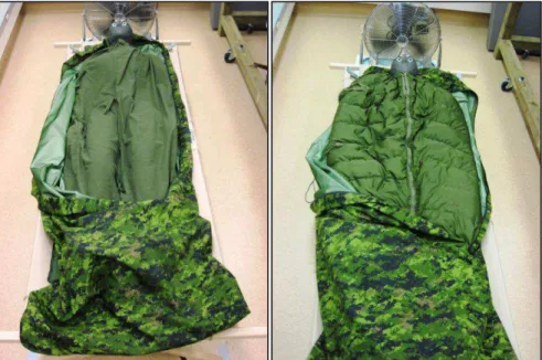
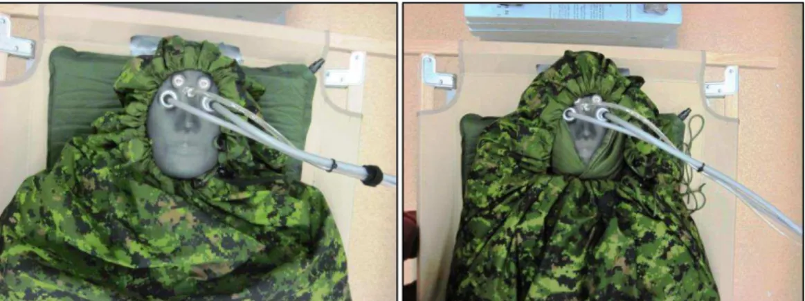
The sleeping bag systems were tested with the main opening lines (i.e. zippers and closure ties) of the modules aligned over the center of the manikin’s chest (SOW Section 3.1.1.2; Figure 14). However, the opening line of the bivy bag was always oriented down the left hand side of the manikin. Also, the bivy bag hood was placed over the manikin’s head with the drawstrings tightened during each test (Figure 15). Photos taken during various thermal insulation tests can be seen in Figures 16-18.
Figure 14: Sleeping bag module closure lines aligned over the center of the manikin’s chest when placed in the bivy bag.
Page 20 of 30
Figure 15: Examples of insulation testing without (orientation 2, left) and with (orientation 3, right) the sleeping bag system hood.
Figure 16: Sleeping bag system thermal insulation testing of orientations 1 (left) and 2 (right).
Figure 17: Sleeping bag system thermal insulation testing of orientations 3 (left) and 4 (right).
OCRE-TR-2015-002
June 11, 2015 Unclassified
Page 21 of 30
Figure 18: Sleeping bag system thermal insulation testing of orientation 5.
3
RESULTS
3.1
Mass
The masses of the various sleeping bag system orientations were measured on March 6, 2015. Repeated measures were not required for the mass testing. The weighing process began within five minutes of removing the sleeping bag system from the conditioning room and took approximately 20 minutes to complete (within the four hour time allotment). The air temperature in the room in which the measurements were taken was 20.6°C (within the required range of 23 +/- 5°C). The results of these tests are shown in Table 1.
Table 1: Masses of the five sleeping bag system orientations.
Orientation Description Mass (g)
1 Liner 660.4
2 Liner, Inner Bag 2886.9
3 Hood, Liner, Inner Bag 3159.4
4 Liner, Outer Bag 2888.6
5 Hood, Liner, Inner Bag, Outer Bag 5389.2
3.2
Packing Volume
The packing volumes of the various sleeping bag system orientations were measured on March 17, 2015. Two repeated measures were taken per orientation and the final packing volume calculations are based on the means of these measurements. The air temperature in the room in which the measurements were taken was 18°C (within the required range of 10-25°C). The results of all of the packing volume tests may be found in Table 2. The equations and full dataset used to calculate the packing volume of the sleeping bag system can be found in Appendix D.
Page 22 of 30
Table 2: Packing volumes of the five sleeping bag system orientations.
Orientation Description Packing Volume (L)
1 Liner 3.823
2 Liner, Inner Bag 17.949
3 Hood, Liner, Inner Bag 21.272
4 Liner, Outer Bag 20.109
5 Hood, Liner, Inner Bag, Outer Bag 35.066
3.3
Thermal Insulation
The thermal insulation values of the various sleeping bag system orientations were measured between May 6, 2015 and May 15, 2015. Three repeated measures were taken per orientation. Throughout the test program, the air temperature in the TML was held at 5°C +/- 0.5°C and the RH was held at 60% +/- 5% (within the stipulated 30-70% range). The results of all of the thermal insulation tests may be found in Table 3. The thermal resistance data and equations used to calculate the thermal insulation (i.e. clo) of the sleeping bag system orientations can be found in Appendix E.
Table 3: Thermal insulation values of the five sleeping bag system orientations (three repeated measures).
Orientation Description
Thermal Insulation (clo) Meas. 1 Meas. 2 Meas. 3 Mean
[SD]
1 Liner 2.1 2.1 2.0 2.1
[0.0]
2 Liner, Inner Bag 4.6 4.5 4.4 4.5
[0.1]
3 Hood, Liner, Inner Bag 5.9 5.7 5.7 5.8
[0.1]
4 Liner, Outer Bag 4.3 4.4 4.4 4.4
[0.1]
5 Hood, Liner, Inner Bag, Outer Bag 7.1 7.3 7.1 7.2
[0.2]
4
DISCUSSION
The tests and results described within this technical report achieve SOW Deliverable 5.1.2.1 of DND SOW 141209a. This concludes the NRC-OCRE portion of the baseline testing of the Canadian Armed Forces 1965 sleeping bag system for mass, packing volume, and thermal insulation. The evaluation testing of the sleeping bag system bids that may replace the current system will involve similar methodologies; however, this testing has not yet taken place. When complete, the results of the evaluation testing will be presented in a separate technical report (thereby achieving SOW Deliverable 5.1.2.2).
5
ACKNOWLEDGEMENTS
The funding required to conduct this test protocol was provided by the Canadian Department of National Defence. On behalf of NRC-OCRE, the authors would like to express their gratitude to DND for the opportunity to participate in this project. Also, the
OCRE-TR-2015-002
June 11, 2015 Unclassified
Page 23 of 30
authors would like to thank their colleagues at NRC-AST and NRC-OCRE for their important contributions. In particular, a special thank you is offered to Mr. Peter Hackett whose expertise was invaluable to the project.
6
REFERENCES
American Association of Textile Chemists and Colorists. (2013). Dimensional Changes
in Commercial Laundering of Woven and Knitted Fabrics Except Wool (AATCC Test Method 96-2012). United States, North Carolina, Research Triangle Park:
Association of Textile, Apparel, and Materials Professionals.
American Society of Testing and Materials. (2014). Standard Practices for Force
Verification of Testing Machines (ASTM E4). United States, Pennsylvania, West
Conshohocken: ASTM International.
American Society of Testing and Materials. (2011a). Standard Test Method for
Measuring Sleeping Bag Packing Volume (ASTM F1853). United States,
Pennsylvania, West Conshohocken: ASTM International.
American Society of Testing and Materials. (2011b). Standard Test Method for
Measuring Thermal Insulation of Sleeping Bags Using a Heated Manikin (ASTM F1720). United States, Pennsylvania, West Conshohocken: ASTM International.
Canadian General Standards Board (2004). Textile Test Methods: Dimensional Change in Domestic Laundering of Textiles (CAN/CGSB-4.2 No. 58). Canada, Ontario, Ottawa: Government of Canada Publications.
Department of National Defence of Canada. (2014). Specification 130906 for Sleeping
Bag System. Directorate of Soldier Systems Program Management. Canada,
Ontario, Ottawa: Government of Canada Publications.
Department of National Defence of Canada. (n.d.). B-GG-302/FP-001 (CFP 302(2), Part
1) Specific Operations, Volume 2 – Arctic and Sub-Artic Operations, Part 1 – Basic Cold Weather Training, Chapter 2 – Personal Clothing and Equipment, Section 2 – Sleeping Bag. Canada, Ontario, Ottawa: Government of Canada
Publications.
Golden, F. & Tipton, M. (2002). Essentials of Sea Survival. Windsor, Ontario, Canada: Human Kinetics.
Page 24 of 30
APPENDIX A – AUTHOR CONTACT INFORMATION
Andrew Baker, MSc (Kin)Research Council Officer – Human Factors National Research Council Canada
Ocean, Coastal, and River Engineering Portfolio 1 Arctic Avenue
PO Box 12093
St. John’s, NL, Canada A1B 3T5 Email: [email protected] Tel: (709) 772-3927
Fax: (709) 772-2462 Jonathan Power, PhD
Research Council Officer – Human Factors National Research Council Canada
Ocean, Coastal, and River Engineering Portfolio 1 Arctic Avenue
PO Box 12093
St. John’s, NL, Canada A1B 3T5 Email: [email protected] Tel: (709) 772-8430
OCRE-TR-2015-002
June 11, 2015 Unclassified
Page 25 of 30
APPENDIX
B
– LAUNDRY SERVICE INVOICE AND
Page 26 of 30
APPENDIX C
– SCALE CALIBRATION
Date of Calibration: February 5, 2015 Start Time: 0805
End Time: 0845
Air Temperature: 20.9°C (measured using a Fluke 233 Remote Display Multimeter) Scale Used: Sartorius LC 34000 P (34,000g capacity)
Table 4: Precision weights used during scale calibration (ANSI/ASTM Class 1 tolerances).
Class Mass (g) Troemner ID Certification Number
Ultra Class Gold 1
500 0710 806662
1000 8988 801336
2000 1497 809164
5000 2505 780140
Table 5: Scale calibration results (calibrations 1-3).
Calibration Number Mass Applied (g) Mass Measured (g)
1 0 0.0 500 499.9 1000 999.8 2000 1999.9 3000 2999.8 3500 3500.0 5000 4999.8 2 0 0.0 500 499.9 1000 1000.0 2000 2000.0 3000 3000.0 3500 3500.1 5000 4999.7 3 0 0.0 500 499.9 1000 999.9 2000 2000.0 3000 2999.9 3500 3500.0 5000 4999.7
OCRE-TR-2015-002
June 11, 2015 Unclassified
Page 27 of 30
Table 6: Scale calibration results (calibrations 4-6).
Calibration Number Mass Applied (g) Mass Measured (g)
4 0 0.0 500 500.0 1500 1500.0 3500 3499.9 8500 8499.9 3500 3499.9 1500 1500.1 500 500.0 0 0.1 5 0 0.0 500 500.0 1500 1500.1 3500 3500.0 8500 8499.8 3500 3499.8 1500 1499.9 500 499.9 0 0.0 6 0 0.0 500 500.0 1500 1499.9 3500 3499.9 8500 8499.9 3500 3499.9 1500 1499.8 500 500.1 0 0.2
Page 28 of 30
APPENDIX D
– SLEEPING BAG SYSTEM PACKING VOLUME
DATA
Table 7: Measurements used to calculate packing volume.
Orientation Repeat H1 (m) H2 (m) Final H1 (m) Final H2 (m) Mean Final Height (m) Packing Volume (L) *IB 1 0.583 0.580 0.080 0.083 0.085 14.126 2 0.576 0.574 0.087 0.089 2 L+IB 1 0.549 0.554 0.114 0.109 0.108 17.949 2 0.555 0.561 0.108 0.102 3 H+L+IB 1 0.539 0.533 0.124 0.130 0.128 21.272 2 0.529 0.539 0.134 0.124 4 L+OB 1 0.544 0.532 0.119 0.131 0.121 20.109 2 0.544 0.548 0.119 0.115 5 H+L+IB+OB 1 0.452 0.449 0.211 0.214 0.211 35.066 2 0.457 0.452 0.206 0.211 1 L* - - - 3.823
*Section 5.6 of ASTM F1853 (ASTM, 2011a) describes a method for determining the packing volume of low volume bags. This methodology was used to determine the volume of the liner module (orientation 1, abbreviated “L” in Table 7). To do so, the packing volume of the inner bag (abbreviated “IB” in Table 7) was measured and then subtracted from the measured packing volume of the liner and the inner bag together (orientation 2, abbreviated “L+IB” in Table 7).
Table 8: Additional measurements used to calculate packing volume.
Value Unit Value Unit Height of Cylinder 76.4 cm 0.764 m
Distance Between Piston Disks 10.1 cm 0.101 m
Inner Cylinder Radius 23.0 cm 0.230 m
Inner Cylinder Radius Squared 529.0 cm2 0.0529 m2
The “final heights” shown in Table 7 were calculated using the following equation: Final Height = HCYL - HMEAS - HDISKS
Where:
HCYL = height from the ground to the top of the cylinder (i.e. the length of the cylinder)
HMEAS= height from the top of the cylinder to the piston’s top disk (measured internally)
HDISKS= distance between the piston’s top and bottom disks
OCRE-TR-2015-002 June 11, 2015 Unclassified Page 29 of 30 V = h (πr2 ) Where:
V = packing volume (measured in cubic meters, m3)
h = final height (described above and measured in meters, m) r = radius of the cylinder (inner edge; measured in meters, m)
Packing volume (V) was then converted from cubic meters (m3) to liters (L) using the following conversion factor:
X m3 · (1000L/1m3) = Y L Where:
X = packing volume coefficient in cubic meters (m3)
Page 30 of 30
APPENDIX E
– THERMAL INSULATION (CLO) DATA AND
EQUATIONS
The thermal manikin’s DAS logs thermal resistance values. These values can be calculated in SI units using the following formula:
R = (Tskin – Tamb) / (Q/A)
Where:
R = thermal resistance (measured in (m2·°C)/W) Tskin = average surface temperature (°C)
Tamb = ambient temperature (°C) Q/A = area weighted heat flux (W·m-2)
To convert thermal resistance (R) into clo units, the following equation was used: clo = R / 0.155
Where:
1 clo = 1 thermal equilibrium equivalent = 0.155 m2·°C/W R = thermal resistance (measured in m2·°C/W)
Table 9: Thermal resistance data and calculated clo values.
Orientation Repeat Number
Mean R
Value* Clo Mean Clo
Standard Deviation 1 L 1 0.329 2.1 2.1 0.0 2 0.324 2.1 3 0.318 2.0 2 L+IB 1 0.708 4.6 4.5 0.1 2 0.701 4.5 3 0.683 4.4 3 L+IB+H 1 0.918 5.9 5.8 0.1 2 0.880 5.7 3 0.887 5.7 4 L+OB 1 0.667 4.3 4.4 0.1 2 0.681 4.4 3 0.682 4.4 5 L+IB+OB+H 1 1.095 7.1 7.2 0.2 2 1.137 7.3 3 1.093 7.1
*Mean R values were calculated by taking an average over 30 minutes of steady state data per test.