Publisher’s version / Version de l'éditeur:
Lab on a Chip, 7, 11, pp. 1546-1552, 2007-08-09
READ THESE TERMS AND CONDITIONS CAREFULLY BEFORE USING THIS WEBSITE. https://nrc-publications.canada.ca/eng/copyright
Vous avez des questions? Nous pouvons vous aider. Pour communiquer directement avec un auteur, consultez la première page de la revue dans laquelle son article a été publié afin de trouver ses coordonnées. Si vous n’arrivez pas à les repérer, communiquez avec nous à [email protected].
Questions? Contact the NRC Publications Archive team at
[email protected]. If you wish to email the authors directly, please see the first page of the publication for their contact information.
NRC Publications Archive
Archives des publications du CNRC
This publication could be one of several versions: author’s original, accepted manuscript or the publisher’s version. / La version de cette publication peut être l’une des suivantes : la version prépublication de l’auteur, la version acceptée du manuscrit ou la version de l’éditeur.
For the publisher’s version, please access the DOI link below./ Pour consulter la version de l’éditeur, utilisez le lien DOI ci-dessous.
https://doi.org/10.1039/b707883h
Access and use of this website and the material on it are subject to the Terms and Conditions set forth at
Microfluidic ELISA on non-passivated PDMS chip using magnetic bead
transfer inside dual networks of channels
Herrmann, Marc; Roy, Emmanuel; Veres, Teodor; Tabrizian, Maryam
https://publications-cnrc.canada.ca/fra/droits
L’accès à ce site Web et l’utilisation de son contenu sont assujettis aux conditions présentées dans le site LISEZ CES CONDITIONS ATTENTIVEMENT AVANT D’UTILISER CE SITE WEB.
NRC Publications Record / Notice d'Archives des publications de CNRC:
https://nrc-publications.canada.ca/eng/view/object/?id=aec624e8-cc12-4bd8-a6b0-0aee2c14d3d3
https://publications-cnrc.canada.ca/fra/voir/objet/?id=aec624e8-cc12-4bd8-a6b0-0aee2c14d3d3
Microfluidic ELISA on non-passivated PDMS chip using magnetic bead
transfer inside dual networks of channels
Marc Herrmann,
abEmmanuel Roy,
bTeodor Veres{*
band Maryam Tabrizian{*
aReceived 24th May 2007, Accepted 17th July 2007
First published as an Advance Article on the web 9th August 2007 DOI: 10.1039/b707883h
Achieving efficient passivation of micro-channels against non-specific adsorption of biomolecules is a critical aspect in the development of microfluidic ELISA systems. Usual surface treatments such as pre-coating of the channels with serum albumin, exposure to oxygen plasma, polyethylene glycol grafting however exhibit a lack of long-term stability, with procedures that can be time-consuming, complex or associated with costly materials and instruments. In this paper, we present a new fluidic design combined with an original strategy of manipulating magnetic beads in order to reduce assay noise in bead-based microfluidic ELISA without the need for prior channel pre-treatment. The novelty of the system relies on the physical separation of the immune complex formation phase and the enzymatic reaction phase into two independent networks of channels. These networks are linked by fluidic bridges, whose openings are controlled by pressure valves, and through which the beads are magnetically transferred. A standard curve for the quantification of a model antibody was obtained within 30 minutes. A detection limit of 100 pg mL21(660 fM) and good linearity of the signal up to 4 ng mL21were observed.
1.0 Introduction
For more than a decade, microfluidics has been employed to adapt standard bench-work bioassays into time- and cost-effective devices. As a result, techniques such as immunoassays are being increasingly used in clinical diagnostics, food safety and environmental applications.1–4 In particular, various platforms for the realization of microfluidic Enzyme-Linked Immuno-Sorbent Assay (ELISA) have been proposed in an effort to reduce the use of large volumes of expensive reagents and hour-long incubation periods, whilst preserving the specificity and the sensitivity of the original assay.5
In conjunction with improvement in design and function-ality, an important part of the development of microfluidic-based systems has focused on creating bio-functional surfaces and, alternatively, on finding means to efficiently passivate microchannels against non-specific adsorption (NSA) of biomolecules. The latter is especially critical in microfluidic ELISA systems, as the large surface-to-volume ratio greatly amplifies the undesired surface effects that generate noise and lower sensitivity. Many research groups have investigated chemical surface modifications of various polymeric materials to limit the effects of NSA.6–12 In particular, surface modifications of poly(dimethylsiloxane) (PDMS) have been extensively explored as it is currently the preferred polymer for biochip fabrication.13–21 Despite many advantages, PDMS is notorious for its high native hydrophobicity and its tendency
to rapidly adsorb biological materials.22 Usual surface treat-ments such as pre-coating of the channels with serum albumin, exposure to oxygen plasma and polyethylene glycol grafting lack long-term stability, and require procedures that are often time-consuming, complex or associated with costly materials and instruments.
In a previous publication, we proposed an innovative concept of stop-flow microfluidic ELISA in which functionalized magnetic beads were used both as a solid-support to sustain the reactive immune complex formation and as a means to increase mixing of the surrounding solution during incubation steps.23In order to establish the fluidic design and protocol for the enzymatic amplification and fluorescent detection, the reactive immune complex was formed off-chip at the surface of the beads, before the reactive beads were injected inside the microfluidic system. With this method, the enzymatic reaction occurred in unused protein-free channels thus considerably limiting the assay noise. The necessity to passivate the PDMS chip was then avoided, which represented a substantial reduction in both the time and the complexity of the assay.
In this paper, we describe the next generation of the system, which combines an original fluidic design and the manipulation of magnetic beads to reduce the noise in bead-based microfluidic immunoassays and realize microfluidic ELISA entirely on-chip, without prior channel passivation. This new approach relies on the physical separation of the immune complex formation phase and the enzymatic reaction phase. Two independent networks of channels are used (dual networks), linked by fluidic bridges through which the beads are magnetically transferred. Pressure valves embedded in bi-layered PDMS24 have been engineered which seal the fluidic bridges when pressure is applied, thus ensuring the complete isolation of the networks and avoiding contamination. Using this new fluidic design and an adapted protocol, a standard curve for the quantification of a model
a
Department of Biomedical Engineering, McGill University, Montreal, QC, H3A 2B4, Canada. E-mail: [email protected]; Fax: (514) 398 7461; Tel: (514) 398 8129
b
Industrial Materials Institute, National Research Council of Canada, Boucherville, QC, J4B 6Y4, Canada. E-mail: teodor.veres@ imi.cnrc-nrc.gc.ca; Fax: (450) 641 5105; Tel: (450) 641 5232
{Co-corresponding authors contributed equally to this work.
antibody was obtained within 30 minutes. A detection limit of 100 pg mL21(660 fM) and good linearity up to a concentration of
4 ng mL21were observed.
2.0 Material and methods
2.1 Fabrication of the bi-layer PDMS microfluidic ELISA chip The master for the control layer was fabricated by standard SU-8 photo-lithography. SU-8 1070 photo-resist (Microchem, Newton, MA) was spin-coated on a silicon wafer to achieve a homogenous layer of 40 mm. The patterns were exposed through a high-definition transparent mask (Fineline Imaging, Colorado Springs, CO) with UV-light and developed, resulting in channels with rectangular cross-sections. The features on the control mask were designed at a 101.6% ratio of the desired dimensions to compensate for the shrinkage of PDMS before alignment. For the fabrication of the master corresponding to the fluidic level, a similar method was applied to construct the two networks of channels. The fluidic bridges were fabricated using AZ 50xt positive resist (AZ Electronic Materials, Branchburg, NJ) and aligned on an aligner EVG 6200 (EV Group, Schaerding, Austria). After development, the master was treated with Trichloro(1H,1H,2H,2H-perfluorooctyl)silane (Sigma-Aldrich, St. Louis, MO) to obtain a hydrophobic surface and facilitate the release of cured PDMS. The surface treatment was followed by reflow of the positive resist for 10 minutes at 120 uC resulting in fluidic bridges with semi-circular cross-sections.
The two layers of PDMS Sylgard184 (Dow Corning, Midland, MI) were cured separately on their respective masters as established by Quake et al.24For the control layer,
PDMS 5 : 1 (elastomer base : curing agent) was mixed, degassed at room temperature and poured to obtain a thickness of about 4 mm. For the fluidic layer, PDMS 20 : 1 was prepared and spin-coated on the fluidic master at a thickness of about 70 mm, forming a 10 mm thick membrane above the 60 mm high fluidic bridges. After a 30 minutes pre-curing step in an oven at 80 uC aimed at minimally hardening both layers of PDMS, the control layer was released from its master and the control inlet punched out. It was then aligned on top of the fluidic layer. The bi-layer assembly was further cured at 80 uC for at least 2 hours to achieve permanent thermal bonding. Finally, the bi-layer PDMS device was pealed off the fluidic master and the inlets and outlets were punched out. The system was then reversibly sealed on a glass slide and ready for use.
2.2 Microfluidic ELISA with dual networks of channels Trizma Base, Tween-20 and glycine were obtained from Sigma-Aldrich (St. Louis, MO) and magnesium chloride from ACP Chemicals (Slough, UK). The streptavidin-coated magnetic beads (Dynabeads1 M-280 Streptavidin) were
purchased from Invitrogen (Burlington, ON) and the rabbit anti-streptavidin IgG from Rockland Immunochemicals (Gilbertsville, PA). The secondary alkaline phosphatase (AP) anti-rabbit antibodies and the enzymatic substrate fluorescein diphosphate (FDP) were purchased from Anaspec (San Jose, CA). All protein dilutions and washing steps were performed
in 0.1 M Tris, 150 mM NaCl, 0.02% Tween-20, pH = 7.4 (TBS-T). FDP was diluted to a final concentration of 4 mM in the reaction buffer consisting of 0.1 M Tris, 10 mM MgCl2, 10 mM
Glycine, pH = 9.0.
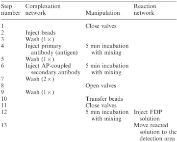
Before mounting the PDMS chip on the mixing platform and securing the valve connection, both the fluidic and the control channels were filled with TBS-T using the Channel Outgas Technique (COT).25 Unless specified otherwise, the protocol for completion of the microfluidic ELISA was performed as reported in Table 1. For each step, a few microlitres of solution (5–15 mL) were deposited in the inlets and flown through the channels by connecting the appropriate outlet to a peristaltic pump in withdrawal mode. After each run, the residual solution trapped at the bottom of the inlets was aspirated to avoid cross-contamination of the sequentially injected solutions.
2.3 Fluorescent signal detection
An inverted microscope (TE2000-U, Nikon), a stereoscopic zoom microscope (SMZ1500, Nikon) and a digital camera (DXM1200F, Nikon) operated with the ACT-1 software were used to acquire pictures of the channels. For fluorescence imaging, the microscope is equipped with a high-pressure mercury lamp (C-SHG1, Nikon) and with the appropriate set of filters for fluorescein (FITC) excitation and emission wavelengths. The intensity of fluorescence in each channel was measured with ImageJ (software for image processing and analysis in Java, http://rsb.info.nih.gov/ij/). All data were normalized by subtracting the fluorescence intensity obtained in the negative control.
3.0 Results and discussion
3.1 Design of microfluidic ELISA with dual networks of channels
The concept of microfluidic ELISA with dual networks of channels relies on the physical separation of the immune complex formation phase and the enzymatic reaction phase Table 1 Protocol for the realization of the microfluidic ELISA with dual networks Step number Complexation network Manipulation Reaction network 1 Close valves 2 Inject beads 3 Wash (16) 4 Inject primary antibody (antigen) 5 min incubation with mixing 5 Wash (16) 6 Inject AP-coupled secondary antibody 5 min incubation with mixing 7 Wash (26) 8 Open valves 9 Wash (16) 10 Transfer beads 11 Close valves 12 5 min incubation with mixing Inject FDP solution 13 Move reacted solution to the detection area
(Fig. 1(a)). A first network of channels (complexation network) is used to achieve the formation of the immune complex, consisting of binding consecutive antibodies and antigens to the surface of the magnetic beads. During this phase, several complex solutions are successively pumped through the network, resulting in the non-specific adsorption of proteins on the channel walls, especially secondary antibodies that would normally cause an elevation in the assay noise. Instead, a second network of channels (reaction network), so far unused and thus free of non-specifically adsorbed proteins, is employed to carry on the enzymatic reaction at the surface of the beads that generates the fluorescent signal. Both networks are independent, linked only by fluidic bridges through which the reactive beads are magnetically transferred.
The complexation network is composed of eight inlets connected by 500 mm wide channels, acting as a diffusion
barrier, to the same number of complexation chambers. Each chamber forms a 480 nL volume in which the beads are magnetically trapped and displaced to prevent local depletion of proteins and homogenize the surrounding solution during incubation periods. Outlet channels connect the eight com-plexation chambers to a single outlet from which the successive solutions can be flown using a peristaltic pump in withdrawal mode.
The reaction network is very similar to the complexation one. Inlets, diffusion barriers and chambers, referred to as reaction chambers, are laid out in an identical manner, parallel to those of the complexation network. The outlet section is however different as the eight independent channels converge to form the detection area. Upstream of the detection area, the outlet channels are adjusted to the same length in order to ensure identical flowing conditions. Downstream from the detection area, the outlet channels merged into a second outlet. 3.2 Engineering of pressure valves
In order to avoid contamination of the reaction chambers, pressure valves were engineered to close the fluidic bridges and completely isolate the two networks from one another. The valves are opened to allow the passage of the beads into the reaction network and then closed again to perform the final steps of the assay.
Due to the design of the fluidic network, the control line for the valves necessarily overlaps fluidic channels in order to reach the bridges (Fig. 1(b)). As the fluidic bridges should be able to close when pressure is applied without disrupting the flow inside the outlet channels, the widths of both the fluidic and control channels were tuned as established by Studer
et al.26 They have demonstrated that as the widths of the overlapping channels increased, less pressure was required to close the valves. In our design, the overlap for operational valves features a 300 6 300 mm area. Non-functional crossings display a limited area of only 50 6 50 mm, thus enabling the selective closing of the bridges.
For the same reason, the fluidic bridges were given a semi-circular cross-section, as opposed to the outlet channels which display a rectangular cross-section.24Yet, semi-circular chan-nels are difficult to obtain using a negative resist such as SU-8. They are preferably produced by reflow of a positive resist. Consequently, the fluidic master was fabricated in three consecutive steps (Fig. 2). First, all the fluidic features but the bridges were realized in SU-8 at a 40 mm thickness. Next, the fluidic bridges, realized in positive resist at a thickness of 50 mm, were aligned so to connect the pairs of chambers. A final baking step at elevated temperature allowed for the positive resist to reflow giving the bridges their final semi-circular shapes.
Using the fabricated fluidic master, bi-layer PDMS micro-fluidic ELISA chips were produced in large quantities with high reproducibility of the valve functionality. The pressure necessary to close the valves is supplied by connecting the control channel to a screw syringe with a blunt-ended needle. To prevent leakage at the connection site, the modified needle is passed through a tight piece of rubber and strongly held down together with the PDMS device. A pressure of about Fig. 1 Layout of the bi-layer PDMS microfluidic ELISA chip (a)
Fluidic level: the solutions are injected into the inlets (1), which are connected to the complexation/reaction chambers (3) via large channels acting as diffusion barriers (2). In the complexation network, outlet channels (4) of equal length link the complexation chambers to the upper outlet (5). In the reaction network, outlet channels (49) adjusted to the same length come closer to form the detection area (6) and then gather into a larger channel connected to the lower outlet (59). The two networks are linked by the fluidic bridges (7). (b) Control level: the control level is composed of a single closed channel (8) fanning into eight branches to form the pressure valves (9) on the top of the fluidic bridges. The fluidic level is represented in light grey to display the overlap of the control channel on the top of the fluidic channels.
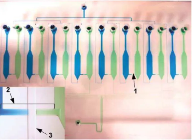
20 PSI in the control line was found to be appropriate to completely and reversibly close the eight valves without disrupting the flow in the outlet channels (Fig. 3). The pressure valves proved to be operational for at least several hours, without observable leakage, pressure drop or contam-ination between the pairs of chambers.
3.3 Proof-of-concept: quantification of a model antibody The operational setup for the realization of the microfluidic ELISA is described in Fig. 4. After priming the channels, the PDMS chip is inserted into its support and the connection for the control channel is secured. A blunt-ended needle, which tightly fits the outlets of the system, is adapted at the end of a tube linked to a peristaltic pump. The pump is then used to flow the diverse solutions through the channels at the required flow rate. The needle can be reversibly and easily switched from one outlet to the other depending on which network is to be operated. Round permanent magnets of 3 mm in diameter are placed directly under the PDMS-glass chip. Eight magnets, one for each of the complexation chamber, are precisely aligned and held together by a plastic piece in which holes the size of the magnets have been drilled. The plastic piece is attached to a mixing platform, which can be moved in all directions with micrometre precision in a pre-determined sequence via a Labview software developed in-house.
In order to demonstrate the concept of dual networks to reduce the noise in bead-based microfluidic ELISA, a standard curve for the quantification of a model antibody was realized without prior channel passivation. For this purpose, commer-cially available magnetic beads coated with a layer of streptavidin, the model antigen, were used to detect anti-streptavidin antibodies, the model analyte (Fig. 5). The protocol for the realization of the microfluidic ELISA is Fig. 2 Fabrication steps for the fluidic master. (a) The two
independent networks of channels are fabricated in the negative resist SU-8. (b) The fluidic bridges are made using the positive resist AZ 50xt. (c) The master is post-baked, hardening the SU-8 and inducing the reflow of fluidic bridges.
Fig. 3 Photograph of the PDMS microfluidic ELISA device showing the two independent networks of channels. The complexation network is filled with a blue dye solution; the detection network is filled with green. All eight pressure valves (1) are closed resulting in the complete isolation of the two networks. The insert provides a close-up view of an interrupted fluidic bridge (2) crossed by the control channel (3).
Fig. 4 Operational platform for microfluidic ELISA: the microfluidic chip is inserted into its support (1). The control channel (2) is connected to a manometer syringe (29) and secured to avoid leakage. One of the fluidic outlets is connected to a peristaltic pump in withdrawal mode (3). Below the chip, the eight permanent magnets (4), mounted on the mixing device (5), are aligned with the complexation chambers.
presented in Table 1. The total assay time was about 30 minutes, mostly due to many pipetting steps, and could be further reduced in a fully automated system. About 106 beads were injected and trapped in each of the eight complexation chambers. During the several incubation peri-ods, the beads were continuously displaced from end to end of the chambers at a velocity of 400 mm s21. The velocity and distance of the magnet to the beads were adjusted so they form a loose bed that is dragged behind the magnet, thus facilitating the penetration and diffusion of solutions between the beads. After both incubation steps with the analyte antibody and the AP-coupled secondary antibody, the beads were washed twice with TBS-T and transferred to the reaction chambers via the fluidic bridges with transiently opened valves. No pre-treatment of the PDMS chip or glass was performed. As a control experiment, the whole assay was also performed in a single network with identical experimental conditions.
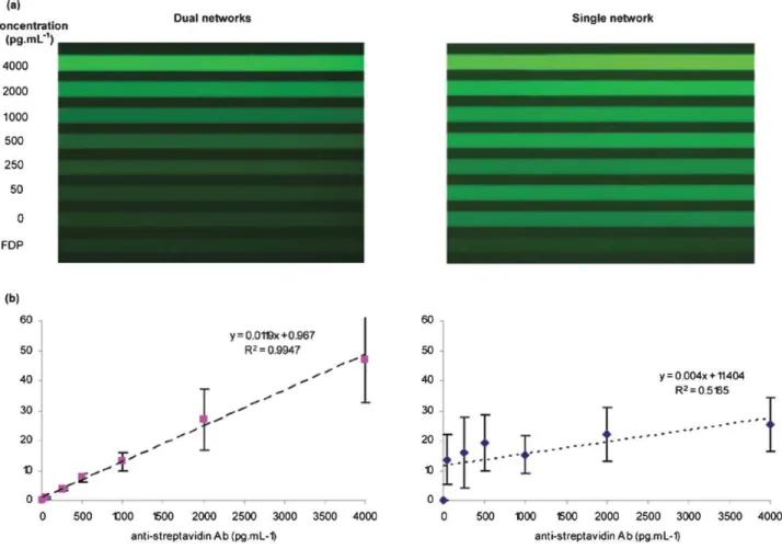
From the fluorescent microscopy images (Fig. 6(a)), it is striking that the level of noise caused by NSA on the channel walls is greatly reduced in the dual network system. Some residual noise is noticeable when comparing channels 1 and 2 in the dual network system (respectively corresponding to un-reacted FDP solution and the negative control, where only the analyte was omitted from the reaction), which might be due to very low NSA at the surface of the beads, however much less than for the same reactions in the single network system.
The reported data are the average of four independent experiments for each of the curves (Fig. 6(b)). To facilitate inter-assay comparison, all values have been normalized by
subtracting the signal obtained for the negative control on the same chip. With the dual network protocol, a limit of detection (LOD) of 100 pg mL21, corresponding to a molarity of about 660 fM (MW = 150 kDa) and good linearity up to 4 ng mL21 were observed for the tested anti-streptavidin antibody. The LOD was taken as 3-times the standard deviation of 5 negative control replicas. For the two highest concentrations, the standard deviations are quite elevated due to the variation in the reaction kinetic from assay to assay performed on separate chips. This variation could surely be minimized in a platform with automated injection and a better control of external conditions such as temperature and ambient light.
When comparing the assays of the single network to the dual networks, both the sensitivity and linearity are significantly improved for the dual network system. While the absolute values are generally higher in the single network experiment, the normalization to the negative control highlights the weaker contrast in this setup between the lowest and the highest concentrations due to the elevated noise that quickly saturates the signal. The sudden increase between the negative control and the lowest concentration of 50 pg mL21can be explained by the fact that several secondary antibodies can bind a non-specifically adsorbed analyte thereby amplifying the noise as compared to directly non-specifically adsorbed secondary antibodies.
The results achieved with the dual network system are close to those obtained in the first iteration of our system where the immune complex was formed off-chip. The decrease in sensitivity, from about 70 fM previously to 660 fM, can be explained by the lesser dispersion of the beads and shorter incubation periods of the on–chip procedure. However, the reduction of the sample size (by a factor of 5) and the shorter total assay time (from several hours to 30 minutes) represent a strong improvement to the global performance of the assay. Moreover, improving bead dispersion and compromising on the incubation times would increase the sensitivity of the assay significantly. Nevertheless, even with the current protocol, the dual network system is among the most sensitive microfluidic immunoassays reported to date,3,4,27–38 without the use of costly, complex and time-consuming pre-treatments.
4.0 Conclusion
In this paper, the novel concept of dual networks of channels was presented. This approach permits noise reduction in bead-based microfluidic ELISA without the need for prior channel passivation. The original design features two independent networks linked by fluidic bridges, whose openings are controlled by pressure valves. Following the formation of the immune complex, the reactive beads are magnetically trans-ferred through the bridges before performing the final steps of the assay in unused protein-free channels. A three-step lithography process was developed for the fabrication of the fluidic master, on which the bi-layer PDMS device was produced in large quantities with constant functionality. The pressure valves were tested and proved to be operational for at least several hours, without observable leakage, pressure drop or contamination between the dual chambers. A protocol was established, which has enabled standard curves to be obtained Fig. 5 Schematic of the immune complex formation and detection
procedure: (a) About 106 streptavidin-coated magnetic beads are
trapped inside the complexation chamber. The anti-streptavidin antibody (analyte) binds specifically to the streptavidin (antigen)-coated beads during a five minute incubation period with mixing. Similarly, the AP-coupled secondary antibody is added to form the reactive immune complex. (b) The valve is transiently opened and the reactive beads are magnetically transferred into the reaction chamber. (c) The enzyme processes the FDP substrate into the fluorescent molecule FITC. While the reaction takes place, the solution is homogenized by displacing the beads. (d) The reacted solution is then pushed into the detection area.
for the quantification of a model antibody in about 30 minutes. A detection limit of 100 pg mL21(660 fM) and good linearity
up to 4 ng mL21 were observed. These data are comparable
to the performance of the most sensitive microfluidic immunoassays reported to date without the need for channel pre-treatment.
Acknowledgements
This work is supported by a joint grant from the Canadian Institute for Health Research and the National Research Council of Canada, as well as by the Fonds quebecois de la recherche de la nature et des technologies through the Centre for Biorecognition and Biosensors. The authors wish to thank Francois Normandin for technical help in building the mixing platform.
References
1 P. Yager, T. Edwards, E. Fu, K. Helton, K. Nelson, M. R. Tam and B. H. Weigl, Nature, 2006, 442, 412–418.
2 S. K. Sia, V. Linder, B. A. Parviz, A. Siegel and G. M. Whitesides,
Angew. Chem., Int. Ed., 2004, 43, 498–502.
3 D. Hoegger, P. Morier, C. Vollet, D. Heini, F. Reymond and J. S. Rossier, Anal. Bioanal. Chem., 2007, 387, 267–275.
4 Y. K. Hahn, Z. Jin, J. H. Kang, E. Oh, M. K. Han, H. S. Kim, J. T. Jang, J. H. Lee, J. Cheon, S. H. Kim, H. S. Park and J. K. Park, Anal. Chem., 2007, 79, 2214–2220.
5 L. J. Lee, S. T. Yang, S. Lai, Y. Bai, W. C. Huang and Y. J. Juang,
Adv. Clin. Chem., 2006, 42, 255–295.
6 D. A. Barrett, M. S. Hartshome, M. A. Hussain, P. N. Shaw and M. C. Davies, Anal. Chem., 2001, 73, 5232–5239.
7 T. Rohr, D. F. Ogletree, F. Svec and J. M. J. Frechet, Adv. Funct.
Mater., 2003, 13, 264–270.
8 J. Liu, T. Pan, A. T. Woolley and M. L. Lee, Anal. Chem., 2004, 76, 6948–6955.
9 C. Li, Y. Yang, H. G. Craighead and K. H. Lee, Electrophoresis, 2005, 26, 1800–1806.
10 R. Lin and M. A. Burns, J. Micromech. Microeng., 2005, 15, 2156–2162.
11 M. Salim, G. Mishra, G. J. Fowler, B. O’sullivan, P. C. Wright and S. L. McArthur, Lab Chip, 2007, 7, 523–525.
12 M. Herrmann, T. Veres and M. Tabrizian, Technical Proceedings
of the 2006 NSTI Nanotechnology Conference, 2006, vol. 2, pp. 244–
247.
13 H. Makamba, J. H. Kim, K. Lim, N. Park and J. H. Hahn,
Electrophoresis, 2003, 24, 3607–3619.
14 E. Delamarche, D. Juncker and H. Schmid, Adv. Mater., 2005. 15 H. Chen, Z. Zhang, Y. Chen, M. A. Brook and H. Sheardown,
Biomaterials, 2005, 26, 2391–2399.
16 H. Makamba, Y. Y. Hsieh, W. C. Sung and S. H. Chen, Anal.
Chem., 2005, 77, 3971–3978.
17 W. Hellmich, J. Regtmeier, T. T. Duong, R. Ros, D. Anselmetti and A. Ros, Langmuir, 2005, 21, 7551–7557.
18 H. Y. Chen, Y. Elkasabi and J. Lahann, J. Am. Chem. Soc., 2006, 128, 374–380.
19 Y. Dong, K. S. Phillips and Q. Cheng, Lab Chip, 2006, 6, 675–681.
20 G. Sui, J. Wang, C. C. Lee, W. Lu, S. P. Lee, J. V. Leyton, A. M. Wu and H. R. Tseng, Anal. Chem., 2006, 78, 5543–5551. Fig. 6 Comparative results for microfluidic ELISA without pre-treatment against NSA using a single network and dual networks of channels. (a) Simultaneous fluorescent detection in all eight channels of the device. (b) Standard curves for the quantification of anti-streptavidin antibodies. Each point represents the average obtained in 4 separate experiments.
21 D. Wu, B. Zhao, Z. Dai, J. Qin and B. Lin, Lab Chip, 2006, 6, 942–947.
22 M. W. Toepke and D. J. Beebe, Lab Chip, 2006, 6, 1484–1486. 23 M. Herrmann, T. Veres and M. Tabrizian, Lab Chip, 2006, 6,
555–560.
24 M. A. Unger, H. P. Chou, T. Thorsen, A. Scherer and S. R. Quake,
Science, 2000, 288, 113–116.
25 J. Monahan, A. A. Gewirth and R. G. Nuzzo, Anal. Chem., 2001, 73, 3193–3197.
26 V. Studer, A. Pandolfi, M. Ortiz, W. F. Anderson and S. R. Quake,
J. Appl. Phys., 2004, 95, 393–398.
27 E. Eteshola and D. Leckband, Sens. Actuators, B, 2001, 72, 129–133.
28 E. Eteshola and M. Balberg, Biomed. Microdev., 2004, 6, 7–9. 29 J. S. Rossier and H. H. Girault, Lab Chip, 2001, 1, 153–157. 30 S. Cesaro-Tadic, G. Dernick, D. Juncker, G. Buurman,
H. Kropshofer, B. Michel, C. Fattinger and E. Delamarche, Lab
Chip, 2004, 4, 563–569.
31 N. Honda, U. Lindberg, P. Andersson, S. Hoffmann and H. Takei,
Clin. Chem., 2005, 51, 1955–1961.
32 V. Linder, S. K. Sia and G. M. Whitesides, Anal. Chem., 2005, 77, 64–71.
33 E. P. Kartalov, J. F. Zhong, A. Scherer, S. R. Quake, C. R. Taylor and W. F. Anderson, Biotechniques, 2006, 40, 85–90.
34 T. Yasukawa, M. Suzuki, T. Sekiya, H. Shiku and T. Matsue,
Biosens. Bioelectron., 2007, 22, 2730–2736.
35 J. F. Dishinger and R. T. Kennedy, Anal. Chem., 2007, 79, 947–954.
36 R. C. Bailey, G. A. Kwong, C. G. Radu, O. N. Witte and J. R. Heath, J. Am. Chem. Soc., 2007, 129, 1959–1967.
37 E. D. Goluch, J. M. Nam, D. G. Georganopoulou, T. N. Chiesl, K. A. Shaikh, K. S. Ryu, A. E. Barron, C. A. Mirkin and C. Liu,
Lab Chip, 2006, 6, 1293–1299.
38 K. Sato, M. Yamanaka, T. Hagino, M. Tokeshi, H. Kimura and T. Kitamori, Lab Chip, 2004, 4, 570–575.