Publisher’s version / Version de l'éditeur:
Vous avez des questions? Nous pouvons vous aider. Pour communiquer directement avec un auteur, consultez la première page de la revue dans laquelle son article a été publié afin de trouver ses coordonnées. Si vous n’arrivez pas à les repérer, communiquez avec nous à PublicationsArchive-ArchivesPublications@nrc-cnrc.gc.ca.
Questions? Contact the NRC Publications Archive team at
PublicationsArchive-ArchivesPublications@nrc-cnrc.gc.ca. If you wish to email the authors directly, please see the first page of the publication for their contact information.
https://publications-cnrc.canada.ca/fra/droits
L’accès à ce site Web et l’utilisation de son contenu sont assujettis aux conditions présentées dans le site LISEZ CES CONDITIONS ATTENTIVEMENT AVANT D’UTILISER CE SITE WEB.
Proceedings of the 5th International Conference on Structures in Fire, pp. 499-507, 2008-05-28
READ THESE TERMS AND CONDITIONS CAREFULLY BEFORE USING THIS WEBSITE.
https://nrc-publications.canada.ca/eng/copyright
NRC Publications Archive Record / Notice des Archives des publications du CNRC :
https://nrc-publications.canada.ca/eng/view/object/?id=21edc904-e7f0-46e9-b6ba-3d5e8b223839 https://publications-cnrc.canada.ca/fra/voir/objet/?id=21edc904-e7f0-46e9-b6ba-3d5e8b223839
NRC Publications Archive
Archives des publications du CNRC
This publication could be one of several versions: author’s original, accepted manuscript or the publisher’s version. / La version de cette publication peut être l’une des suivantes : la version prépublication de l’auteur, la version acceptée du manuscrit ou la version de l’éditeur.
Access and use of this website and the material on it are subject to the Terms and Conditions set forth at
Mechanical characterization of fibre-reinforced polymers for numerical fire endurance modelling
Chowdhury, E. U.; Eedson, R.; Bisby, L. A.; Green, M. F.; Bénichou, N.; Kodur, V. K. R.; Fyfe, E.
http://irc.nrc-cnrc.gc.ca
M e c h a n i c a l c h a r a c t e r i z a t i o n o f f i b r e
r e i n f o r c e d p o l y m e r s f o r n u m e r i c a l f i r e
e n d u r a n c e m o d e l l i n g
N R C C - 5 0 0 9 6
C h o w d h u r y , E . U . ; E e d s o n , R . ; B i s b y , L . A . ;
G r e e n , M . F . ; B é n i c h o u , N . ; K o d u r , V . K . R . ;
F y f e , E .
A version of this document is published in / Une version de ce document se trouve dans: Proceedings of the Fifth International Conference Structures in Fire, Singapore, May 28-30, 2008, pp. 499-507
The material in this document is covered by the provisions of the Copyright Act, by Canadian laws, policies, regulations and international agreements. Such provisions serve to identify the information source and, in specific instances, to prohibit reproduction of materials without written permission. For more information visit http://laws.justice.gc.ca/en/showtdm/cs/C-42
Les renseignements dans ce document sont protégés par la Loi sur le droit d'auteur, par les lois, les politiques et les règlements du Canada et des accords internationaux. Ces dispositions permettent d'identifier la source de l'information et, dans certains cas, d'interdire la copie de documents sans permission écrite. Pour obtenir de plus amples renseignements : http://lois.justice.gc.ca/fr/showtdm/cs/C-42
MECHANICAL CHARACTERIZATION OF FIBRE REINFORCED
POLYMERS FOR NUMERICAL FIRE ENDURANCE MODELLING
E. U. CHOWDHURY1, R. EEDSON2, L. A. BISBY3, M. F. GREEN4, N. BENICHOU5, V.K.R. KODUR6 and E. FYFE7
ABSTRACT
Concerns associated with fire remain an obstacle to applications of fibre reinforced polymer (FRP) materials in buildings and parking garages due to their sensitivity to high temperatures as compared with other structural materials. This paper presents the preliminary results of an experimental investigation to characterize the mechanical properties of unidirectional infrastructure FRPs under various loading and thermal regimes, ranging from ambient temperature, eventually up to 600°C. Tensile, lap splice bond, and FRP to concrete bond tests are being conducted under both steady state and transient thermal and loading regimes. Results from initial mechanical testing of unidirectional carbon/epoxy FRP (CFRP) coupons are presented in this paper. The CFRP coupons retained 40 to 60% of their room temperature tensile strength and 50 to 80% of their room temperature tensile elastic modulus when tested under steady state thermal conditions between 86°C and 200°C. The implications of these test results for numerical fire endurance modelling of FRP strengthened concrete structures are discussed.
1
Graduate Student, Queen’s University, Department of Civil Engineering, Kingston, ON, Canada, K7L 3N6 email: chowdhury@ce.queensu.ca
2
Graduate Student, Queen’s University, Department of Civil Engineering, Kingston, ON, Canada, K7L 3N6 email: rob.eedson@ce.queensu.ca
3
Assistant Professor, Queen’s University, Department of Civil Engineering, Kingston, ON, Canada, K7L 3N6 email: bisby@civil.queensu.ca
4
Professor, Queen’s University, Department of Civil Engineering, Kingston, ON, Canada, K7L 3N6 email: greenm@civil.queensu.ca
5
Research Officer, National Research Council of Canada, Ottawa, ON, Canada, K1A 0R6 email: Noureddine.Benichou@nrc-cnrc.gc.ca
6
Professor, Michigan State University, Lansing, Michigan, USA, 48824 email: kodur@egr.msu.edu
7 President, Fyfe Company LLC, San Diego, California, USA, 92121 email: ed@fyfeco.com
1 INTRODUCTION
Fibre reinforced polymer (FRP) materials are increasingly being used in repairing and retrofitting reinforced concrete structures that have deteriorated from damage caused by electrochemical corrosion or from sustaining loads higher than their design. There are many advantages in externally strengthening concrete structures with FRP materials rather than with steel, including resistance to corrosion, and ease and speed of application. In spite of FRPs’ advantages, fire resistance remains a significant obstacle to the application of FRPs in many buildings and parking garages because of these materials’ combustibility and susceptibility to degradation of mechanical and bond properties at elevated temperatures. A research study is being conducted at Queen’s University in conjunction with the National Research Council of Canada (NRC) and industry partners to investigate the effects of fire on FRP strengthened concrete structures. As part of that overall research effect, this paper presents test results to characterize the mechanical properties of selected currently available infrastructure FRPs under various loading and thermal regimes, ranging from ambient temperature to 300°C. Results from these tests will be used to develop analytical models to represent the stress-strain behaviour of FRPs for subsequent use in predictive fire simulation software which is currently being developed by the authors.
2 RESEARCH SIGNIFICANCE
The current paper represents part of a larger study to investigate the performance of FRP strengthened concrete members under exposure to standard fires. A major component of this larger research program involves developing numerical models that can simulate the heat transfer within these FRP strengthened concrete structures and their structural response at high temperature.1,2,3 If successful, rational and defensible numerical models could considerably reduce the costs incurred in standard fire testing of full-scale specimens. A detailed knowledge of the thermal and mechanical behaviour of FRP materials at high temperature, which is extremely scarce for the specific systems under consideration, is critical for such models to accurately simulate the behaviour of FRP strengthened concrete structures under fire. In addition, the critical temperature above which the FRP composite will have inadequate structural strength remains unknown. Such information is important for setting defensible service temperature limits for these systems.
3 EXPERIMENTAL PROCEDURE
In this paper, preliminary results from a larger material testing program are presented. In the overall material testing program, selected commercially available FRP strengthening systems will be tested under various loading and thermal regimes. The mechanical properties and bond strength of FRP materials are known to begin degrading at temperatures close to or exceeding the glass transition temperature (Tg) of the polymer resin component of the FRP
material, which is typically between 65 and 120°C.4 Hence, the tests presented herein were conducted at ambient temperature and temperatures near the resin’s Tg. Prior to the tension
tests, differential scanning calorimetry (DSC) was performed on four samples of FRP composite by the authors to determine the glass transition temperature of the FRP material. Based on the DSC results, tension tests were conducted at temperatures 15°C below and above the glass transition temperatures to investigate the mechanical degradation near the
glass transition temperature. Additional tests were conducted at 200°C to observe the material’s performance at temperatures well above the glass transition temperature.
In the overall material testing program, tensile, lap splice, and FRP-to-concrete bond tests will be conducted. The experimental procedure for the current study is based on earlier research performed at Queen’s University on the residual properties of FRPs after exposure to elevated temperature.5,6 Details of the specimens for the three types of tests to be performed are shown in Figure 1. Both steady and transient thermal and loading regimes are being considered. Preliminary results for some of the tensile specimens are included in this paper. The FRP specimens, which were made with two plies of sheet, had a nominal thickness of 2.0 mm. The tension tests were conducted in a Universal Testing Machine (UTM) (Figure 2), which has an integrated, custom designed thermal chamber (with internal dimensions of 250 mm width by 250 mm depth by 300 mm height) and a maximum load capacity of 600 kN.
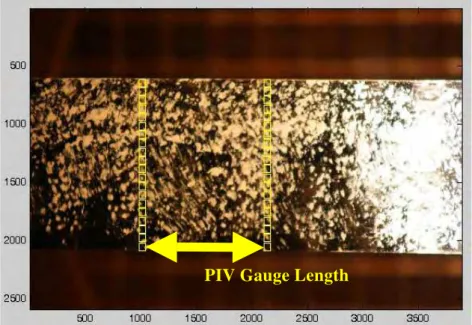
For this paper, tension tests on carbon/epoxy FRP (CFRP) coupons were conducted under a steady-state heating condition. The CFRP specimens were heated to the specified temperature at a constant heating rate of 10°C/min, held at the specified temperature for 15 minutes, and then loaded at a crosshead stroke rate of 3 mm/min. At this point, no investigation on heating rate or loading rate, both of which may be important, has been conducted. Figure 3 shows the temperature-time curve of the design and measured temperature achieved by the FRP specimens (i.e., the intended chamber ramp and soak regimes, along with the temperature measured on the surface of the FRP coupon at its midpoint). The slight lag in the “actual” curves is due to the fact that these temperatures were measured using bondable surface thermocouples, such that the thermal mass of the coupons decreased the measured temperatures. In general, both the ramp rate and hold temperatures were as desired. During the tension tests, the middle 300 mm of the FRP specimens was heated, as shown in Figure 2(b), to prevent failure near the grip region (which would be a matrix-dominated failure mode). Axial strains were measured using a deformation measurement technique based on particle image velocimetry (PIV) and close-range digital photogrammetry.7 In this measurement technique, digital images were captured of the FRP specimens inside the thermal chamber using a high-resolution digital camera. Using PIV, 20 virtual strain gauges were created across the width of the coupons by defining 40 pixel “patches” on the images of the FRP specimens, as shown in Figure 4. During PIV analysis, the digital images were processed to track the movement of the pixel patches and thus measure the displacements of the patches between two or more digital images. Based on the displacements measured from the image processing, the variation in axial strain was calculated across the width of the coupons at various load levels. This information was subsequently used to calculate the elastic modulus of the coupons during testing as per ACI 440 requirements8.
4 RESULTS AND DISCUSSION
Initial results from tensile tests of carbon/epoxy FRP coupons are presented in this paper. The glass transition temperature of the FRP material was determined to be 101 ± 2°C based on an average of four DSC runs (with Tg determined on the second heating cycle).
Based on this measured Tg value, initial test temperatures were selected on the basis of
recommended service temperature limits as per ACI 440 requirements9 as 20°C (ambient), 86°C (Tg - 15°C), 116°C (Tg + 15°C) and 200°C. Additional temperatures will be investigated
in future tests, up to and including temperatures at which decomposition of the matrix polymer is expected to occur.
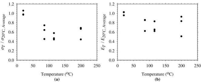
Three direct tension tests were performed at each of the above temperatures. Figure 5 shows the normalized tensile strength and elastic modulus data with increasing exposure temperature. Because of the well known difficulty of measuring strain at elevated temperatures during material testing, axial strains in the coupons were measured using PIV analysis. The strain analysis was performed for twenty virtual axial strain gauges across the width of the coupons, and the axial strains were observed to vary by up to 0.05% across the width of the FRP coupon specimens at a given level of total axial load. As an example, Figure 6 shows the axial strain profiles measured across the width of one of the coupons tested at room temperature at three increasing load levels. Interestingly, this figure shows that the axial strain varies considerably (by up to 25% of the average reading) across the coupon’s width. It is likely that this strain variation results from non-homogeneities in the coupons, as well as uneven gripping at the coupon’s ends (even though these coupons were carefully tested according to applicable guidelines8).
Also shown in Figure 6 are horizontal lines showing the strains measured by a bonded foil gauge at the specimen centreline at the same load levels. It is clear that there is good agreement between the foil and optical gauges. Additional validation of this optical technique for measuring strains in FRPs is given by Bisby et al.10. Despite the variation in observed axial strain over the coupon width, the axial strains from all 20 virtual strain gauges were averaged across the width to obtain a global stress-strain curve for the coupon. From this global stress-strain curve, the tensile chord modulus was calculated using stress values corresponding to 0.1% and 0.3% strain8.
At room temperature, the CFRP coupons had a tensile strength of 703 ± 34 MPa and a tensile elastic modulus of 82 ± 3 GPa at 20°C. Figure 5 shows that the CFRP coupons tested thus far experienced strength losses between 20 and 60% and losses of tensile elastic modulus between 20 and 40% at 86°C, or Tg - 15°C. Comparable losses of strength and modulus were
observed at both 116°C and 200°C, with little apparent additional degradation in either strength of stiffness at these higher temperatures.
The above data suggest that the coupons tested herein lose up to 60% of their room temperature strength at temperatures 15°C below their matrix Tg, but that further heating does
not cause additional strength loss. Thus, the authors suspect that this behaviour is due to loss of interaction and load sharing between fibres for all elevated temperature exposures, due to matrix softening, such that the elevated temperature strength and stiffness values effectively represent the results that would be obtained by testing dry fibres. Tests are currently underway to confirm this hypothesis. The data also suggest that, provided that adequate anchorage is maintained, the CFRP strengthening system tested appears able to retain at least 40% of its room temperature strength at temperatures up to 200°C. Clearly, additional testing is needed to support this conclusion.
While considerable variability exists in the data shown in Figure 5, it should be noted that none of the coupons failed near the grips. Furthermore, all coupons that were tested at high temperature ruptured in the region of the FRP that was inside the thermal chamber, indicating that the reduced strength and stiffness was not a consequence of thermal degradation in the gripping region. Failure of the CFRP coupons at room temperature was sudden and violent and occurred along a horizontal line across the coupons’ width. Coupons tested at 86°C were less violent than at 20°C, but displayed a similar failure mode. At 116°C and 200°C, the coupons split longitudinally (refer to in Figure 7) as they approached failure and thus failed more gradually. This behaviour is thought to be associated with loss of interaction between the individual fibre rovings due to resin softening at elevated temperature.
5 IMPLEMENTATION IN STRUCUTRAL FIRE MODELS
As previously mentioned, the long term objective in performing the tests such as those presented above is to develop empirical/analytical relationships to describe the variation in mechanical and bond properties of various currently available FRP strengthening materials and systems with temperature for subsequent use in numerical fire simulation models. To develop analytical descriptions of the data presented previously, the authors have, on the basis of previously published research on the high temperature performance of polymer composites4,11,12, selected a sigmoid function to represent mechanical property degradation. This function can be expressed using the following form:
(
)
(
)
⎟ ⎠ ⎞ ⎜ ⎝ ⎛ + + − − ⎟ ⎠ ⎞ ⎜ ⎝ ⎛ − = 2 1 tanh 2 1 a c T b a f f oIn the above expression, f is the material property at elevated temperature, T, fo is the room
temperature material property, and a, b, and c, are parameters that determine the lower asymptote, midpoint, and curvature of the sigmoid curve. Using a non-linear multi-parameter least squares regression analysis, the coefficients, a, b, and c in the above equation can easily be determined to provide an analytical approximation to the observed behaviour. This has been done for the experimental data presented herein in Figure 8. Clearly, given the variability in the data obtained to date, additional data are needed before these predictions can be used with confidence. It is expected4,12 that degradation of bond properties will follow a similar, although more severe, degradation trend at high temperature.
Once the analytical relationships are derived for strength, stiffness, and bond properties, they will be incorporated into numerical models to predict the fire endurance of FRP strengthened reinforced concrete columns. Details of these column models have been presented elsewhere2.
6 FUTURE TESTING
The data presented in this paper represent a preliminary investigation only. The reader will recognize that a considerable amount of additional testing is required before the true behaviour of FRP strengthening systems, under load, at elevated temperature can be accurately described. Tests are currently underway to study both the transient and steady-state creep performance of FRP strengthening systems under various loading and thermal regimes. Similar tests are planned to study the FRP-to-FRP and FRP-to-concrete bonds under both static and dynamic thermal and loading regimes. Furthermore, the effects of heating rate and thermal history will also be examined.
7 SUMMARY AND CONCLUSIONS
This paper has presented the initial results of an ongoing experimental study aimed at developing a more complete understanding of the degradation in mechanical and bond properties of FRP strengthening systems for infrastructure at elevated temperatures. Based on the results of these preliminary tests on FRP coupons, the following conclusions can be drawn:
• The wet lay-up carbon/epoxy FRP material tested in the current paper suffered a 20 to 60% degradation of tensile strength and a 20 to 40% degradation of tensile elastic modulus at temperatures 15˚C below the glass transition of its resin matrix.
• The loss of strength and stiffness appears to be due to loss of load sharing between the individual fibre rovings, essentially resulting in dry fibre behaviour at temperatures close to or exceeding the resin’s Tg.
• The data presented herein provide preliminary evidence that wet lay-up FRP materials such as that tested in the current paper may be able, with sufficient anchorage, to maintain 40 to 50% of their tensile strength at temperatures well in excess of their resins’ Tg. A
total loss of tensile strength is expected beyond the thermal decomposition temperature of the polymer resin. Additional testing is required to support these conclusions.
8 ACKNOWLEDGEMENTS
The authors are members of the ISIS Canada Research Network and would like to acknowledge the support of the Networks of Centres of Excellence Program of the Natural Science and Engineering Research Council of Canada. We would also like to thank the National Research Council of Canada, Fyfe Co., and Sika Corp for their support of this project.
9 REFERENCES
[1] Bisby, L.A., Kodur, V.K.R. and Green, M.F. “Fire endurance of fiber-reinforced-polymer confined concrete columns”, ACI Structural Journal, 102(6), pp. 883-891, 2005.
[2] Chowdhury, E.U., Bisby, L.A., Green, M.F., Bénichou, N and Kodur, V.K.R. “Fire behaviour of FRP wrapped square reinforced concrete columns”, CDCC-07, Quebec City, Canada, pp. 83-90, 2007.
[3] Williams, B., Kodur, V., Green, M.F. and Bisby, L. “Fire endurance of fiber-reinforced polymer strengthened concrete T-beams”, ACI Structural Journal, 105(1), pp. 60-67, 2008. [4] Bisby, L.A., Green, M.F. and Kodur, V.K.R. “Response to fire of concrete structures that incorporate FRP”, Progress in Structural Engineering and Materials, 7(3), pp. 136-149, 2005. [5] Bisby, L.A. and Foster, S.K. “High temperature residual bond properties of FRP
strengthening systems for concrete”, CDCC-07, Quebec City, Canada, pp. 193-200, 2007. [6] Foster, S.K. and Bisby, L.A. “High temperature residual properties of externally-bonded FRP systems”, FRPRCS-7, Kansas City, USA, pp. 1235-1252, 2005.
[7] White, D.J., Take, W.A. and Bolton, M.D. “Soil deformation measurement using particle image velocimetry (PIV) and photogrammetry”, Géotechnique, 53(7), pp. 619-631, 2003. [8] ACI. “Guide Test Methods for Fiber-Reinforced Polymers (FRPs) for Reinforcing or Strengthening Concrete Structures”, ACI 440.3R-04, American Concrete Institute, Farmington Hills, MI, 40 pp, 2004.
[9] ACI. “Guide for the Design and Construction of Externally Bonded FRP Systems for Strengthening Concrete Structures”, ACI 440.2R-02, American Concrete Institute, Farmington Hills, MI, 45 pp, 2002.
[10] Bisby, L.A., Take, W.A. and Caspary, A. “Quantifying strain variation in FRP confined concrete using digital image analysis”, 1st Asia-Pacific Conference on FRP in Structures (APFIS 2007), Hong Kong, December 12th-14th, pp. 599-604, 2007.
[11] Dimitrienko, Y.I. “Thermomechanics of Composites under High Temperatures”, Klewer Academic Publishers, London, 347 pp, 1999.
[12] Katz, A., and Berman, N. “Modeling the effect of high temperature on the bond of FRP reinforcing bars to concrete”, Cement and Concrete Composites, 22, pp. 433-443, 2000.
700 700 63.5 63.5 51.0 mm overlap 25 .4 65.0 50.0 180.0 20 0.0 70 0 63 .5 FRP specimen 1 20. 0 FRP specimen GFRP tabs (c) (a) (b) FRP specimen GFRP tabs 63.5 63.5 A A Section A-A
Fig. 1 – FRP specimen schematics for (a) tensile tests (presented), (b) FRP-to-FRP bond-overlap test (not presented), and (c) FRP to concrete bond test (not presented). Dimensions
are in mm.
(a) (b) (c)
Fig. 2 – (a) Universal testing machine, thermal chamber, and data acquisition system, (b) thermal chamber, and (c) wedge-action gripping system outside the chamber.
Time (minutes) 0 10 20 30 40 Tem p er atu re ( ο C) 0 50 100 150 200 250 86οC 116οC 200οC Design curve Actual curve
Fig 3. Design (desired) and actual (observed specimen) temperatures during heating.
PIV Gauge Length
Fig 4. Test patches on FRP specimens for image processing using PIV (photo rotated 90˚ clockwise).
Temperature (oC) (a) 0 50 100 150 200 250 σT / σ 20 οC , A ver age 0.0 0.2 0.4 0.6 0.8 1.0 1.2 Temperature (oC) (b) 0 50 100 150 200 250 ET / E20 οC , Average 0.0 0.2 0.4 0.6 0.8 1.0 1.2
Fig 5. (a) Normalized strength and (b) normalized tensile elastic modulus of CFRP coupons with increasing temperatures.
Percentage of Total Width (%)
0 10 20 30 40 50 60 70 80 90 100 Ax ia l St ra in (%) 0.0 0.2 0.4 0.6 0.8 1.0 5.6 kN 14.6 kN 25.5 kN
Fig 6. Strain variation across the width of a typical FRP specimen under increasing axial tensile loads
(a) (b)
Fig 7. Failure of CFRP coupons at 200°C (a) just before failure, and (b) just after failure. Loss of interaction between rovings is evident (photos rotated 90˚ clockwise).
Temperature (oC) (a) 0 50 100 150 200 250 σT / σ20 ο C , Av era g e 0.0 0.2 0.4 0.6 0.8 1.0 1.2 Temperature (oC) (b) 0 50 100 150 200 250 ET / E 20 οC , Av erag e 0.0 0.2 0.4 0.6 0.8 1.0 1.2
Fig 8. (a) Normalized strength and (b) normalized tensile elastic modulus of CFRP coupons with increasing temperatures, including preliminary analytical least-squares best-fit sigmoid