Publisher’s version / Version de l'éditeur:
2009 Cansmart Workshop, pp. 197-205, 2009-01-01
READ THESE TERMS AND CONDITIONS CAREFULLY BEFORE USING THIS WEBSITE. https://nrc-publications.canada.ca/eng/copyright
Vous avez des questions? Nous pouvons vous aider. Pour communiquer directement avec un auteur, consultez la première page de la revue dans laquelle son article a été publié afin de trouver ses coordonnées. Si vous n’arrivez pas à les repérer, communiquez avec nous à [email protected].
Questions? Contact the NRC Publications Archive team at
[email protected]. If you wish to email the authors directly, please see the first page of the publication for their contact information.
NRC Publications Archive
Archives des publications du CNRC
This publication could be one of several versions: author’s original, accepted manuscript or the publisher’s version. / La version de cette publication peut être l’une des suivantes : la version prépublication de l’auteur, la version acceptée du manuscrit ou la version de l’éditeur.
Access and use of this website and the material on it are subject to the Terms and Conditions set forth at
High temperature integrated ultrasonic transducers for engine condition monitoring
Kobayashi, M.; Wu, K.-T.; Jen, C.-K.; Bird, J.; Galeote, B.; Mrad, N.
https://publications-cnrc.canada.ca/fra/droits
L’accès à ce site Web et l’utilisation de son contenu sont assujettis aux conditions présentées dans le site LISEZ CES CONDITIONS ATTENTIVEMENT AVANT D’UTILISER CE SITE WEB.
NRC Publications Record / Notice d'Archives des publications de CNRC: https://nrc-publications.canada.ca/eng/view/object/?id=3078d363-544b-4ac2-88f9-90570a98e4f0 https://publications-cnrc.canada.ca/fra/voir/objet/?id=3078d363-544b-4ac2-88f9-90570a98e4f0
Cansmart 2009
International Workshop
SMART MATERIALS AND STRUCTURES
22 - 23 October 2009, Montreal, Quebec, Canada
HIGH TEMPERATURE INTEGRATED ULTRASONIC TRANSDUCERS
FOR ENGINE CONDITION MONITORING
M. Kobayashi1, K.-T. Wu2, C.-K. Jen1, J. Bird3, B. Galeote3 and N. Mrad4
1
Industrial Materials Institute, National Research Council, Boucherville Quebec, Canada J4B 6Y4
[email protected]; [email protected] 2
Department of Electrical and Computer Engineering, McGill University Montreal, Quebec, Canada H3A 2A7
Institute for Aerospace Research, National Research Council Ottawa, Ontario, Canada K1A 0R6
[email protected]; [email protected] 4
Department of National Defence, Defence R&D Canada, Air Vehicles Research Section, National Defence Headquarters, Ottawa, Ontario, Canada K1A 0K2
ABSTRACT
Employing a portable on-site fabrication kit, high temperature integrated ultrasonic transducers (IUTs) made of bismuth titanate piezoelectric film, of thickness greater than 50 µm, have been coated directly onto a modified CF700 turbojet engine outer casing, oil sump and supply lines and gaskets using sol-gel spray technology. Transducers top electrodes, electrical wires, conducting adhesive bond, connectors and cables have all been successfully tested for temperatures up to 500°C. The excellent ultrasonic performance of these IUTs is demonstrated in this paper and the potential applications for the non-intrusive real-time temperature and lubricant oil quality and metal debris monitoring have been identified and discussed.
Keywords: Structural health monitoring, Non-destructive evaluation, Integrated ultrasonic
INTRODUCTION
The increasing demand to improve the performance, reduce downtime, increase reliability and extend the life of engines requires the use of sensors for continuous engine conditions monitoring during development and service. It is established that methods employing piezoelectric ultrasonic transducers (UTs) are widely used for real-time, in-situ or off-line non-destructive evaluation (NDE) of large metallic structures including airplanes, automobiles, ships, pressure vessels, pipelines, etc. because of their subsurface inspection capability, fast inspection speed, simplicity and cost-effectiveness [1-3]. In this investigation the objective is to develop and evaluate effective integrated UT (IUT) technology to perform non-intrusive engine NDE and structural health monitoring (SHM). The intended applications include non-intrusive real-time temperature, lubricant oil quality, and metal debris monitoring within the turbojet engine environment. For this purpose a portable on-site IUT fabrication technique is most desirable. Additionally, because engines operate at elevated temperatures, the developed IUT technology including piezoelectric UTs together with electrical wire, conductive bonding agent, connectors and cables must be assessed. In this study the assessment is aimed and limited to temperatures up to 500°C.
PORTABLE ON-SITE INTEGRATED ULTRASONIC TRANSDUCER FABRICATION
The engine to be used is a modified (fan module removed) CF700 turbojet engine as shown in Figure 1 at the Institute for Aerospace Research (IAR), of the National Research Council (NRC) of Canada. In order to coat high temperature IUT directly onto the engine components and on-site, a portable IUT fabrication kit has been developed. The fabrication of IUTs involves a sol-gel based sensor fabrication process [4-6]. Such process consists of six main steps: (1) preparing high dielectric constant lead-zirconate-titanate (PZT) solution, (2) ball milling of piezoelectric bismuth titanate (BIT) powders to submicron size, (3) sensor spraying using slurries from steps (1) and (2) to produce the thin film UT, (4) heat treating to produce a solid BIT composite (BIT-c) thin film UT, (5) Corona poling to obtain piezoelectricity, and (6) electrode painting for electrical connectivity. Steps (3) and (4) are used multiple times to produce optimal film thickness for specified ultrasonic operating frequency and performance. Silver or platinum paste was used to fabricate top electrodes. BIT-c was used because of its high temperature (500°C) endurance [5, 6]. Figure 2 shows the lower and upper levels of the developed portable IUT fabrication kit. The kit with dimensions of 0.8×0.53×0.3 m3
, consists of the following item:
a. BIT powders and PZT solution (used in step 1).
b. One ball milling device, sand papers, detergent, acetone and methanol for sample cleaning (used in step 2).
c. One air brush, one compressor air device, and two glass beakers for cleaning of air brush (used in step 3).
d. One heat gun, one propane torch, two high temperature gloves, and one thermo-couple (used in step 4).
e. One Corona poling device (used in step 5).
f. One silver and one platinum paste pen, and one multi-meter to measure resistance of the electrode and temperature together with a thermocouple. Special high temperature electrical connection accessories are included (used in step 6).
g. One suite case for housing all the components of the portable kit.
Fig. 1: Modified CF700turbojet engine.
(a) (b)
Fig. 2: A portable IUT fabrication kit; (a) interior lower level and (b) interior upper level.
Portable on-site Fabrication Kit Fig. 3: A portable fabrication kit.
Such a developed portable IUT fabrication kit (Figure 3) can be conveniently carried for on-site application of the technology onto target components. Figure 4 illustrates the instrumentation of two IUTs, consisting of BIT-c films with 500°C platinum paste top electrodes, onto the outer casing of the modified CF700 turbojet engine. This Figure further
shows the bonding conductive material that was applied onto the platinum paste, and the 500°C signal transmitting wires (Figure. 4(b)). In general one wire would be sufficient for one IUT; however, for redundancy two wires were installed. The principle of the use of the IUT for the non-intrusive real-time and continuous internal engine temperature measurements is based on using ultrasonic pulses and determining the time of flight as reported in [7, 8].
500\ C IUTs
(a)
500oC Conducting Bond
500oC IUTs
Platinum Paste
Top Electrode 500oC Conducting Wire
(b)
Fig. 4: Two IUTs installed on-site at the top of the engine outer casing and (b) 500°C wires bonded to the platinum electrodes.
Additionally, for ultrasonic temperature monitoring of 500°C, IUTs were also coated onto two different engine access covers as shown in Figure 5. These access covers have also been instrumented with conventional thermocouples. In such a configuration, temperature measured by ultrasound can be compared with those measured by thermocouples. These sensors have been installed onto the modified CF700 turbojet engine as shown in Figure 6. Figure 7 shows the typical measured ultrasonic signals traversed back and forth within the gasket thickness in pulse/echo mode at room temperature for the IUT coated onto the gaskets as shown in Fig. 6. The center frequency of these IUTs is around 11 MHz. Ln is the nth round trip echo through the thickness of the gasket.
500oC Conducting Bond 500oC IUTs Silver Paste Top Electrode 500oC Conducting Wire 500oC Conducting Bond 500oC IUTs Silver Paste Top Electrode 500oC Conducting Wire Thermocouple Installation Location Thermocouple Installation Location
500oC IUTs + Wire Connection (a) 500oC IUTs + Wire Connection (b)
Fig. 6: Installed access covers on the modified CF700 turbojet engine.
Time Delay (µs) A m p lit ud e ( A rb . Un it ) L2 L1 L3 L4 L5 (a) L2 L1 L3 L4 L5 Time Delay (µs) A m plit ude ( A rb . Unit ) (b)
Fig. 7: Typical ultrasonic signals of the IUT coated onto the access covers shown in Fig. 6.
HIGH TEMPERATURE TESTS ON THE ELECTRICAL IUT CONNECTORS
In order to test the fabricated IUTs made of BIT-c film and platinum top electrodes, electrical connectors, and conductive adhesive, a 25.4 mm diameter 150 mm long steel rod, simulating engine component, has been used for the deposition of IUTs (Figure 8(a)). The center frequency of these IUTs is about 10 MHz at room temperature. Such an assembly was placed into a furnace (Figure 8(b)) and thermally cycled from room temperature to 500°C. The results of two thermal cycles are shown in Figure 9. The upper two pictures on the left and two on the right indicate the ultrasonic signals with high signal to noise ratio (SNR) which traveled a distance of 300 mm and 600 mm, respectively. The lowest and right part in Figure 9 indicates the measured ultrasonic velocity profile in the steel rod during the thermal cycles. In the middle of Figure 9, the attenuation number (Attn) indicates the total loss of IUT, electrical connections and ultrasonic attenuation propagating via a round trip of the 150 mm long steel rod. At 500°C this attenuation was only 6 dB.
500oC Connector 500oC Conducting Bond 500oC Wire (a)
500oC Thermal Cycle Test
(b)
Fig. 8: (a) One IUT made of BIT-c films on top of a steel rod (delay line) together with top electrode, wire connection, conducting adhesive bond, electrical connector and cable; (b) 500°C thermal cycle test chamber.
Room temperature to 500°C
Thermal Cycle Test Ultrasonic Velocity Profile
Ultrasonic signal at 500°C Ultrasonic signal at 500°C
Zoomed Signal Zoomed Signal
After a distance of 300 mm After a distance of 600 mm
Fig. 9: Thermal cycle tests of 500°C BIT-c film IUT directly coated on top of a 150 mm long steel rod including top electrode, conducting bond, wire, connector and cable.
IUTS FOR LUBRICANT OIL QUALITY AND METAL DEBRIS MONITORING
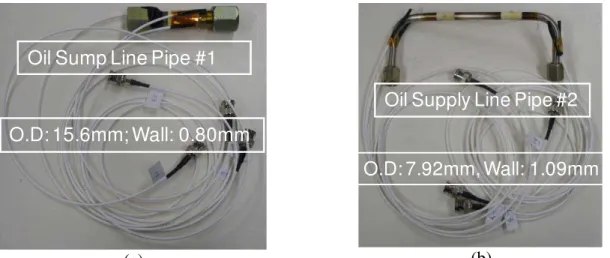
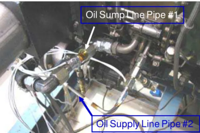
It is also the intention of this work to perform non-intrusive real-time continuous monitoring of the lubricant oil quality and metal debris in the engine oil system. For such purpose one oil sump line and one oil supply line of the turbojet engine, shown in Figure 10, are instrumented. Figure 11 illustrates the instrumented IUTs together with the necessary prototype electrical connections for the oil sump and supply line, respectively. The cables used can only sustain temperatures of up to 200°C; hence they were properly installed as shown in figure 12. Figure
13 illustrates typical measured ultrasonic signals traversed back and forth within the pipe thickness in pulse/echo mode at room temperature for the IUT coated onto the oil sump and supply lines, respectively. The center frequencies of the L echo, shown in Fig. 13, are at 10 and 17 MHz, respectively. L is the n round trip echo through the wall thickness of the pipe. During actual operations, the ultrasonic measurements will be carried out in the transmission mode and ultrasonic signals with higher SNR than those shown in Fig. 13 are expected. Such an expectation comes from previous experiments which simulated the monitoring of lubricant quality and metal debris [9].
1
n th
Oil Sump Line Pipe #1
Oil Supply Line Pipe #2 (a)
O.D: 7.92mm Wall: 1.09mm
O.D: 15.60mm Wall: 0.80mm
Supply Line Pipe #2
500oC IUTs
Sump Line Pipe #1
500oC IUTs
(b)
Fig. 10: (a) Standard engine oil sump and supply lines, (b) IUTs coated onto special oil sump and supply lines.
Oil Sump Line Pipe #1
O.D: 15.6mm; Wall: 0.80mm
(a)
Oil Supply Line Pipe #2
O.D: 7.92mm, Wall: 1.09mm
(b)
Fig. 11: (a) Oil sump line (b) Oil supply line equipped with IUTs and prototype electrical connections.
Oil Sump Line Pipe #1
Oil Supply Line Pipe #2
Fig. 12: Oil sump and supply lines installed onto the modified CF700 turbojet engine.
Time Delay (µs) A m plit ude ( A rb . Un it ) L2 L1 L3 L4 L5 (a) Time Delay (µs) L2 L1 L3 L4 L5 A m pl it ude ( A rb. Uni t) (b)
Fig. 13: Typical ultrasonic signals of the IUT coated onto the (a) Oil sump and (b) supply lines and operated in pulse/echo mode at room temperature.
CONCLUSIONS AND DISCUSSIONS
Employing a developed portable on-site fabrication kit, high temperature integrated ultrasonic transducers (IUTs) made of thick BIT composite piezoelectric film have been coated directly onto a modified CF700 turbojet engine outer casing, oil sump and supply lines and gaskets using a sol-gel spray technology that consists of six main steps. The top electrodes, electrical wires, conducting adhesive bond, connectors and cables have been also tested successfully at temperatures of up to 500°C. The center frequencies of these IUTs were around 10 to 17 MHz. Ultrasonic signals obtained in pulse/echo measurements of these IUTs are excellent and it is expected that high temperature ultrasonic performance will be obtained in the transmission mode as well. The potential applications of the developed IUTs include non-intrusive real-time temperature, lubricant oil quality and metal debris monitoring which will be carried out in pulse/echo and transmission mode, respectively.
ACKNOWLEDGMENT
Financial support from the Natural Sciences and Engineering Research Council of Canada is acknowledged.
REFERENCES
1. Gandhi, M.V. and Thompson, B.S., “Smart Materials and Structures”, Chapman & Hall, NY, 1992.
2. Ihn, J.-B. and Chang, F.-K., “Ultrasonic non-destructive evaluation for structure health monitoring: built-in diagnostics for hot-spot monitoring in metallic and composite structures”, Chapter 9 in Ultrasonic Nondestructive Evaluation Engineering and Biological Material Characterization, edited by Kundu T., CRC Press, NY, 2004.
3. Birks, A.S., Green, R.E. Jr. and McIntire, P. ed., “Nondestructive Testing Handbook”, 2nd Edition, vol.7, Ultrasonic Testing, ASNT, 1991.
4. Barrow, D.A., Petroff, T.E., Tandon, R.P. and Sayer, M., “Characterization of thick lead zirconate titanate films fabricated using a new sol gel based process”, J. Appl. Phys., vol.81, 1997, pp. 876-881.
5. Kobayashi, M. and Jen, C.-K., “Piezoelectric thick bismuth titanate/PZT composite film transducers for smart NDE of metals”, Smart Materials and Structures, vol.13, 2004, pp.951-956.
6. Kobayashi, M., Jen, C.-K., Bussiere, J.F. and Wu, K.-T., “High temperature integrated and flexible ultrasonic transducers for non-destructive testing”, NDT&E Int., vol.42, 2009, pp.157-161.
7. Walker, D.G., Myers, M.R., Yuhas, D.E. and Mutton, M.J., “Heat flux determinations from ultrasonic pulse measurements”, Proc. IMECE, ASME, Boston, MA, 2008.
8. Yuhas, D.E., Mutton, M.J., Remiasz, J.R. and Vorres, C.L., “Ultrasonic measurements of bore temperature in large caliber guns”, Proc. Review of QNDE, vol.28, 2008, pp.1759-1766.
9. Kobayashi, M., Jen, C.-K., Moisan, J.-F., Mrad, N. and Nguyen, S.B., “Integrated ultrasonic transducers made by sol-gel spray technique for structural health monitoring,” Smart Materials and Structures, vol.16, 2007, pp.317-322.