HAL Id: cea-02434543
https://hal-cea.archives-ouvertes.fr/cea-02434543
Submitted on 10 Jan 2020
HAL is a multi-disciplinary open access archive for the deposit and dissemination of sci-entific research documents, whether they are pub-lished or not. The documents may come from teaching and research institutions in France or abroad, or from public or private research centers.
L’archive ouverte pluridisciplinaire HAL, est destinée au dépôt et à la diffusion de documents scientifiques de niveau recherche, publiés ou non, émanant des établissements d’enseignement et de recherche français ou étrangers, des laboratoires publics ou privés.
M. Girard, S. Albaladejo, D. Cambet, S. Armiroli, R. Cotillard, G. Laffont, O.
Carra, G. Prele
To cite this version:
M. Girard, S. Albaladejo, D. Cambet, S. Armiroli, R. Cotillard, et al.. Development Of Innovating Na Leak Detector On Pipes. International Conference on Fast Reactors and Related Fuel Cycles Next Generation Nuclear Systems for Sustainable Development FR17, Jun 2017, Yekaterinburg, Russia. �cea-02434543�
Development of innovating Na leak detector on pipes
M. Girard1, S. Albaladejo1, D. Cambet1, S. Armiroli2, R. Cotillard2, G. Laffont2,O. Carra3, G. Prêle4
1
DEN/DTN/STCP/LIET, CEA-Cadarache, France 2
DRT/ LIST/DM2I/LCAE, CEA-Saclay, France 3
AREVA NP, Lyon, France 4
EDFSEPTEN, Villeurbanne, France
E-mail contact of main author: marianne.girard@cea.fr
Abstract: Within the ASTRID reactor project, CEA, EDF and AREVA NP, have launched a R&D program
focused on the low leak rates detection of sodium on pipes. This program is focused on the development of innovating detectors, multilayer-type and Optic Fiber, involving tests in the FUTUNa sodium loop. This loop is designed to produce very accurate sodium leak rates within a range around 1 cm3/min, the tests being performed at different temperature (up to 550°C) on large-diameter pipe mock-ups (D 800 mm) at ambient atmosphere. This paper presents the first series of tests carried out with various materials of the first and second layer of the detector. The results are compared and discussed as well as the observations made after removing the mock-ups. The most interesting result of the overall tests is a detection time less than 2 hours for the two types of detectors.
Key Words: In-service inspection, Na leakage detection, Multilayer detector, Optical Fiber Sensor
1. Introduction
Within the framework of the ASTRID reactor project (Advanced Sodium Technological Reactor for Industrial Demonstration), CEA, EDF and AREVA NP, have launched a R&D program focused on low leak rates detection of liquid sodium on pipes. Mainly due to some unreliability of the Na leak detection systems previously used on Na reactor pipes [1] [2] this program is focused on the development of innovating detector systems, among which the two with which this paper deals: the Optic Fiber (O.F) and the multilayer detector. This latter is based on detection by short-circuiting within a direct contact with the sodium medium.
Thus in year 2011 a testing program has been proposed by the Nuclear Energy Division (DEN) for the development of a multilayer detector technology including tests undertaken in a sodium loop at CEA, Cadarache. The FUTUNa loop allows operating at various temperatures up to 550°C with very accurate sodium leak rates within the range [0.05-30 cm3/min]. The relevant tests are conducted with different pipe mock-ups including the two detector systems, the O.F being developed by the Technological Research Division (DRT) at CEA, Saclay.
This paper presents the progress of the multilayer detector development, providing results of the FUTUNa tests which were undertaken within different material layers and various O.F layings on the mock-ups. The overall results are discussed and a status on the ongoing R&D studies is presented.
2. The two innovating Na leak detection systems
The two relevant detectors have been identified for uses on specific circuits of the ASTRID
[100-700 mm] diameter range of pipes. They have been selected until now as two complementary detector systems.
2.1 Description and principle of the Multilayer detector
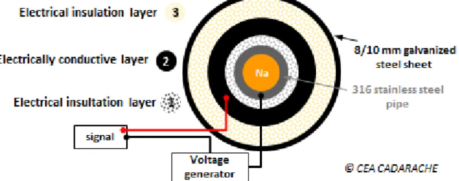
As described in the CEA patent [3], the concept of this innovating multilayer detector is as follows: the pipe is totally covered with (see FIG.1),
-(1) an electrically insulating first layer essentially made up of fibers and extending against the outside surface of the pipe;
-(2) an electrically conductive second layer essentially constituted by agglomerated carbon or graphite fibers and extended against the outside surface of the first layer; -(3) a thermally insulating third layer essentially constituted by fibers extended
against the outside surface of the second layer; -a rigid wall in order to protect the overall mounting.
Its principle is based on the loss of electrical insulation between the liquid sodium and the electrically conductive layer (2) of the pipe. In case of Na leak, the Na liquid flows through the first electrically insulating layer (1) and will be able to make contact between the pipe and the conductive layer (2). The electrical properties of the Na medium will close the detection circuit which, in turn, will trigger an alarm.
Figure 1 : Schematic design and principle of the multilayer Na leak detector (sectional view)
This detector corresponds to an evolution of the previous sandwich-like detector, the latter being preferentially implemented on welds, pipe bends of Na circuits [1] [2].
Concerning this new technology, their up-dated advantages can be listed below: -fiability avoiding problems of triggered “false alarms”;
-rapid detection for low Na leak rate (< 10 cm3/min);
-precise location of the leak within the implementation of dedicated sections along the pipe ;
-cost-effective solution: the purchase and installation of this solution is at present time 20 to 40% cheaper than for wires of steatite beads-detection type.
2.2 Description of the Optical Fiber sensor
Single mode optical fibers are promising candidates for instrumentation within any nuclear facilities due to:
-low intrusive effects;
-electromagnetic immunities;
-precise location of the leak within the O.F routing on the pipe.
The relevant optical fiber sensing technology is based on a frequency analysis of the Rayleigh backscattered light along the core of the optical fiber. Collecting and processing this backscattered signal, an OFDR (Optical Frequency Domain Reflectometry) trace is obtained and distributed along the length of the optical fiber’s core. Thus for the relevant application, the O.F is used as a distributed temperature transducer and the temperature change can be followed in quasi real time over a predefined segment of the optical fiber (Lmax.= 70 m). The temperature measurement resolution is typically 1°C for a 1 mm-spatial resolution. No temperature calibration is required, as this one is only necessary for temperature operating ranges higher than 650°C.
This innovative solution for liquid sodium leakage detection was first implemented on a FUTUNa mock-up in 2012 using a gold-coated single mode fiber for a test temperature at 560°C [4]. The O.F is inserted in a metallic cladding (1 mm-diameter) to avoid any damages by a direct contact with liquid sodium.
3. The testing program
A testing program taking into account the maturity of each innovating system has been drawn up at CEA since 2011. The LCAE (Sensors and Electronics Laboratory) of the DRT that conducts its own R&D testing program on the O.F supplied the optic fibers and was involved by the signal processing during the overall FUTUNa tests.
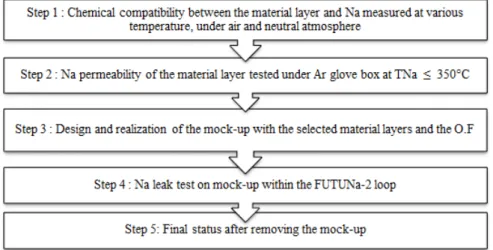
The study and selection of the multilayer materials have been conducted within the steps detailed hereafter on FIG. 2. The O.F is integrated right from step 3 for the Na leak tests on mock-ups.
Figure 2 : R&D testing program launched by CEA for the multilayer and optic fiber Na-leak detectors
The goal of the preliminary experiments performed on mock-ups (Step 4) was to validate the multilayer detector concept within the selection of the electrical conductive layer 2. The further experiments were focused on the study of both the two first layers, keeping in mind that the requirement “easy to assemble on pipes” must be met for a further industrial use on reactor circuits.
The “Chemical compatibility” of Step 1 is measured by means of micro-gas chromatography (µGC) and Differential Scanning Calorimetry (DSC). The “Na permeability” of Step 2 is evaluated within a dedicated mounting placed in an argon glove-box with appropriate analyses performed after the test.
The Na loop test nominal parameters
The nominal parameters required for the Na leak tests are totally linked to the ASTRID reactor concept. As can be seen, the leak rate value belongs to the low Na leak rate range, i.e. [1-10 cm3/min] that corresponds to the more penalizing configuration for leak detections:
-Na leak rate: 1 cm3/min -Detection time ≤ 10 hours
-Na temperature : 180°C ≤ TNa ≤ 550°C
-Pipe diameter: 100 mm ≤ outer diameter ≤ 700 mm -Ambient environment: air, inert atmosphere.
These criteria will be taken into account as much as possible to set the Step 1 and Step 2 experiments and the tests carried out on the mock-ups in the FUTUNa Na loop. It is obvious that the required criteria may evolve over time as for example the “inert atmosphere environment” criteria that turns out to be the most recent required criteria.
4. Na-leak tests on mock-ups 4.1 The FUTUNa-2 facility
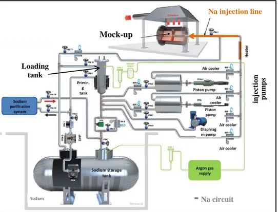
The FUTUNa-2 loop (FUTUNa-1 loop was modified in 1995-1997) has been chosen because it is designed to produce very accurate sodium leak rates within a range between 0.05 and 30 cm3/min and furthermore it has an experimentation area in which different types of mock-ups can be installed. The current outlines of the loop are presented in FIG.3.
Figure 3 : Schematic diagram of the FUTUNa-2 loop
Operating principle
The sodium contained in the storage tank (150 L) is heated until it reaches its liquefaction temperature. This sodium is then pumped by an immersed electromagnetic pump so as to fill a loading tank (pressurising argon). In this configuration, the test can be conducted with 2
Mock-up Loading tank
-
Na circuit Na injection line in je ct io n p u m p spiston pumps at a flow rate between 0.05 and 2 cm3/min by continuously injecting the sodium into the test mock-up at the required flow rates. The monitoring of the injection is performed indirectly by measuring the sodium level in the loading tank. Furthermore leak tightness is required in specific places along the Na circuit of the loop in order to avoid any parasite leaks on the relevant circuit.
The pipe mock-up
The tests are performed on a 2m-long pipe mock-up made of 316 L stainless steel which is horizontally positioned with a slope of 3%. The mock-up is equipped with two 1m-long heating cores to simulate the sodium temperature inside the pipe. The injection of sodium is realized in the upper part of the pipe by means of a dedicated injection line.
As shown in FIG. 4, the Na injection line is equipped with several thermocouples up to the “Na injector outlet” which is a 6 mm-conical leak hole itself surrounded by thermocouples giving operating temperatures (TC Na 3 and 4). The “skin temperature” of the pipe is monitored by several thermocouples with 1 mm cladding.
Figure 4: Schematic diagram of thermocouples implemented on the Na injection line and on the outer skin of the pipe
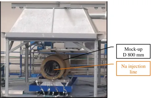
The device is placed on its support structure so as to position the injection line with respect to the central part of the pipe. The overall mounting is placed under an extraction hood as can be seen hereafter on the view of FIG. 5.
Figure 5 : Lagged pipe mock-up (DN 800 mm) placed in the FUTUNa experiment area
Na injection line
Mock-up D 800 mm
Test principle
Test section and sodium injection line are preheated at the nominal parameter of the test. Piston pumps are operated and checked for its operation and performance. The electrically conductive second layer (2) detector is tested for leak indication before conducting the experiment by short circuiting.
As the injection started, a spark plug Na-leak detector (see DPS1 in FIG. 4) positioned at the injector outlet indicates when sodium leaks outside the pipe mock-up. The test is considered to start at this moment and the volume of the sodium leak is recorded as of time t0.
The test ends if the electrically conductive second layer (2) triggers the alarm. If not, the injection pump is manually stopped after 10 hours (24 hours for two tests). The Na circuit is then drained, all heaters are switched off and the facility is cooled to room temperature to allow the complete removing of the mock-up the day after.
The mock-up mounting, the FUTUNa tests and the removal of the mock-ups are conducted by the appropriate personnel of the LIET (Laboratory of Instrumentation and Technological Tests of the DEN) as well as the glove box tests of Step 2.
4.2 The multilayer detector mock-up
The material layers selected for the study belong to insulating fibers of silica oxides (or aluminum, magnesium or calcium oxides) for layer (1) and to carbon, graphite or stainless steel for layer (2). Layer (3) is made of an insulating material mostly made of silica oxides named Rock wool which is certificated as PMUC (French acronym of “Products and Equipments suitable for use in Nuclear power plants”).
The choice for the material of the 1rst layer was made as a result of feedback from Step 1 and Step 2 of the CEA testing program (see FIG. 2). Note that corrosion phenomena can occur on the pipe surface close to the Na leak area and under this 1rst material layer. This particular point should be further studied, since a corrosion resistance is required for the overall mounting.
Instrumentation
The Na expansion is monitored through “skin temperature” thermocouples on the pipe and through the O.F disposed directly on the pipe and even inside the 1rst lagging layer (1) if the fiber length in study allows it. An example of a helical pattern along the pipe is shown in FIG. 6 corresponding to a potential further industrial routing on reactor pipes.
Skin thermocouples Wire leak detector Wire leak detector Na injector outlet Optic Fiber Figure 6: Instrumentation and O.F implemented on the pipe (OD-800mm)
before mounting the multilayer detector
In addition and according to the objective of the tests or to safety reasons, some wire-type detection lines can be implemented on specific parts of the pipe (see FIG.6) or/and on the externallagging layer (3).
5. Test results
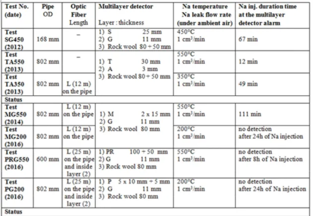
Table 1 hereafter summarizes the series of tests undertaken on mock-ups on the FUTUNa loop between 2012 and 2016 with the relevant test results in term of duration time detection from the multilayer detector. The thickness of each specific layer is indicated. The overall testing was conducted on 316 L stainless steel pipes whose outer diameters are in the [100 - 800 mm] range.
Table 1: FUTUNa loop tests undertaken for the multilayer detector and O.F studies on mock-ups
5.1 First series of mock-up tests
The first tests including the observations made after removing the mock-ups have led for each material layer to the following synthesis:
Layer (1)
S: interesting mock-up test results (detection time < 67 min) but this material will be replaced for further testing with a similar SiO2-based material belonging to PMUC, see layer 1 of the next PRG550 test ;
T: interesting mock-up test results (detection time < 49 min) and material qualified for corrosion resistance but industrial-scale production in rigid board forms that does not fit with the needs.
Layer (2)
G: positive mock-up test results but its use imposes a limit on the maximum operating temperature of 350°C under air at the 1rst/2nd layer interface;
A: positive mock-up test results but oxidation processes have been observed on this felt material after removing the mock-ups for tests undertaken at 550 and 350°C. Additional tests performed in furnaces have led to the same conclusions with the loss of the electrical properties due to corrosion process.
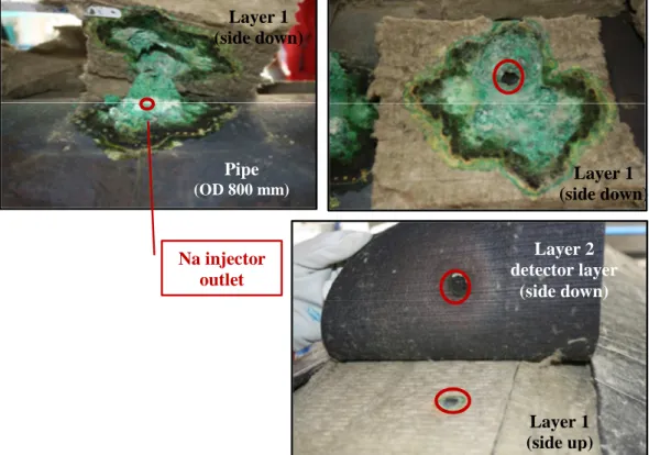
To illustrate a “positive mock-up test result”, FIG.7 presents some views related to the test performed at TNa = 550°C for which detection occurred after only 12 minutes of Na injection at 1 cm3/min-leak rate (see test TA550 in Table 1). The impact of the 12 cm3 of Na can be observed nearby the injector outlet area on the pipe, through the thickness of the 1rst layer (30 mm-thickness) and on the 2nd detector layer. The affected area covers approximately 150 x 100 mm of the pipe surface. A slight color change can be observed on layer (2) close to the injector outlet location meaning that the detector layer may have reached locally its maximum operating temperature (i.e. 650°C) during this test.
Figure 7- Mock-up after FUTUNa test TA550: sodium reaction products on the pipe, on layer 1 and 2 with respect to the Na injector outlet (triggered alarm of the multilayer detector at tinj=12 min)
5.2 Second series of mock-up tests
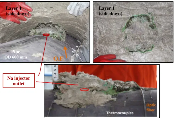
FIG. 8 hereafter illustrates the PRG550 test performed at 550°C for which no detection within the multilayer detector occurred after 8 hours of Na injection. The detector layer has not been reached by the sodium and it turns out that all the injected volume, i.e. 480 cm3, has been trapped within the first 30 mm of the 150 mm-lagging layer 1. The affected area covers here approximately 200 x 200 mm of the pipe surface.
Layer 1 (side down) Layer 1 (side down) Layer 1 (side up) Layer 2 detector layer (side down) Pipe (OD 800 mm) Na injector outlet
Figure 8 - Mock-up after FUTUNa test PRG550: aspects of the pipe and layer1 after 8 hours of Na injection (no triggered alarm of the multilayer detector after tinj= 8 h)
A 24m-length O.F. was wrapped around the pipe and layer (1) as described on FIG.9a. This deployment allowed through temperature change measurements both the Na leakage detection on the pipe (see FIG. 9b) and the monitoring of the Na flow front on layer 1 (see FIG.9c).
Figure 9 - FUTUNa test PRG550: O.F signal after ~ 10 min and 2h20min of Na injection at 550°C
Early temperature changes were observed on the pipe within the first minutes of Na injection at L = 38, 40 and 42 m, i.e. close to the Na outlet injector whereas temperature changes were visualized on layer 1 after a 1h43min-injection duration time. Note that this O.F has not been damaged by direct contact with liquid sodium during the test.
Layer 1 (side down) Pipe OD 600mm Layer 1 (side down)
O.F
. Na injector outlet 9b) 9c)Regarding the multilayer detector, this series of tests has led to the following synthesis:
Layer (1)
M: interesting mock-up test result with a 30 mm-layer thickness at 550°C but negative result at 200°C, high cost compared to other materials that would be a penalizing criterion ;
PR: belongs to PMUC but negative mock-up test result with a 150 mm-layer thickness at 550°C;
P: negative mock-up test result with a 65 mm-layer thickness at 200°C.
Layer (2)
A layer (2) material with a higher upper operating temperature limit under air (350°C for G material) would allow reducing the layer (1) thickness and thereby ensuring the Na flux to pass through this thinner 1rst layer around the pipe.
6. Conclusions
A series of tests has been performed with two innovating detectors, i.e. multilayer-type and Optical Fiber sensor, involving leak tests on pipe mock-ups in the FUTUNa sodium loop. The tests have led to interesting results with an experimental proof of concept for the relevant multilayer detection system. Optic fiber uses have demonstrated that the Na leak is early detected and can be monitored as a localized temperature change along the O.F length on the mock-up.
Considering these test results and new requirements issued in 2016 by the ASTRID project, the next FUTUNa loop tests will be focused on Na leak expansion study on mock-ups under neutral environment (nitrogen) and low temperature (180-200°C). Furthermore, this new testing program would enhance the understanding of the process (mechanical or chemical one) which controls the Na flow expansion through the material layers.
Acknowledgements
The authors are thankful to the FUTUNa loop staff S. Lusso, P. Charvet and S. Serbout (Process Engineering student) who performed the mock-up preparations and the testing program.
References
[1] J. Guidez, “PHENIX, the experience feedback” edp sciences, April 2013
[2] J. Guidez, G. Prêle “SUPERPHENIX-Technical and Scientific Achievements” Atlantis Press, January 2017 [3] S. Albaladejo, R. Zanolin, “Leak detection device and coating intended for a fluid transport or storage member and comprising said section device” CEA Patent 2010/03573, International Publication WO 2012/032233 A1
[4] E. Boldyreva, R. Cotillard and al., “Distributed temperature monitoring for liquid sodium leakage detection using OFDR-based Rayleigh backscattering”, Proceeding 9157, 23rd International Conference on Optical Fibre Sensors, June 2014, Spain.
[5] S. Armiroli, R. Cotillard and al.,”Sodium leakage detection on a lagged pipe using OFDR-based Rayleigh backscattering”, Proceeding of ANIMMA (in progress) - International Conference on Advancements in Nuclear Instrumentation Measurement Methods and their Applications, June 19-23, 2017, Belgium.