HAL Id: hal-02516136
https://hal.archives-ouvertes.fr/hal-02516136
Submitted on 23 Mar 2020
HAL is a multi-disciplinary open access
archive for the deposit and dissemination of
sci-entific research documents, whether they are
pub-lished or not. The documents may come from
teaching and research institutions in France or
abroad, or from public or private research centers.
L’archive ouverte pluridisciplinaire HAL, est
destinée au dépôt et à la diffusion de documents
scientifiques de niveau recherche, publiés ou non,
émanant des établissements d’enseignement et de
recherche français ou étrangers, des laboratoires
publics ou privés.
Current Source Power Supply for DBD Excilamps
Hubert Piquet, Sounil Bhosle, Rafael Diez, Marc Cousineau, Mahamat
Abakar Djibrillah
To cite this version:
Hubert Piquet, Sounil Bhosle, Rafael Diez, Marc Cousineau, Mahamat Abakar Djibrillah. Current
Source Power Supply for DBD Excilamps. AMPL’2009 Atomic and Molecular Pulsed Lasers
AMPL-2009, Sep AMPL-2009, Tomsk, Russia. �hal-02516136�
Current Source Power Supply for DBD Excilamps
Hubert Piquet
1, Sounil Bhosle
1, Rafael Díez
1,2, Marc Cousineau
1, Mahammat Djibrillah
1 1LAPLACE laboratory, UMR 5213 CNRS-INPT-UPS, Université de Toulouse,
2, rue Camichel, BP7122 - 31071 Toulouse Cedex 7 - France
2
Electronics Department, Pontificia Universidad Javeriana, Bogotá Colombia
[email protected]
ABSTRACT
The electrical power delivered to the gas in a XeCl Dielectric Barrier Discharge exciplex lamp, is analyzed, applying causality criteria based on an equivalent circuit model of the DBD; this power is shown to be controllable by the current supplied to the lamp.
This highly desired property is obtained by means of a specific power supply topology, which concepts and design are discussed. Experimental prototype of a current-mode converter operating in discontinuous current mode around 50 kHz is presented and its capability to control the amount of energy transferred during each current pulse is shown.
The capability of this power supply to sustain specific operating conditions for the DBD lamp, with a very stable behavior, (even with a very low current, thus obtaining a single discharge channel) is illustrated. The results concerning the coupling of this converter with a XeCl excilamp are presented and the influence of the supply parameters on the 308nm emission of a Xenon/Chlorine excilamp is analyzed. The shape of the pulsed UV power radiated by the lamp is experimentally shown to be very similar to the one of the current which actually flows into the gas mixture.
The UV radiation is demonstrated to be tightly correlated to the current injected into the gas and controllable by means of the available degrees of freedom offered by the control of the power supply. Measurements of the output characteristics and performances of the system are discussed.
Keywords: DBD, excimer, current-mode, power supply, static converter.
1. INTRODUCTION
Dielectric Barrier Discharge exciplex lamps are usually associated with voltage-controlled electric generators: the classical solutions for laboratories experimental setups are built around large bandwidth linear amplifiers connected to step-up transformers [1]; for more industry oriented solutions, pulsed voltage sources are often considered, where switched voltages are generated by means of circuits including power semiconductors [2], [3]. When submitted to such voltages, the DBD lamp in return imposes current of very narrow spike shape in the circuit. The analysis of the UV response of the excilamp shows a similar behavior, concerning the UV radiation, with spikes which duration are also very short, compared to the operating period of the whole equipment. The characteristics of the current spikes (magnitude, duration, frequency) are really difficult to control by means of voltage-controlled electric generators [6], [7]. The aim of our approach is to consider the power supply as a mean to control the UV emission of the excilamp. On the basis of an analysis of the causality of the power transfers between the power supply and the lamp, we have favored current controlled topologies.
A specific solution is described in this paper and key aspects of the design of the latter, being absolutely different from the classical one (with voltage source behavior) are also introduced.
The performances of this electric generator, associated with a XeCl excilamp are presented; they confirm the validity of the reasoning which has driven us to consider current-source power supplies.
2. POWER TRANSFER
In this section, an analysis of the power transfers between an electric generator and a DBD excilamp is carried out. Causality considerations, derived from a classical model of a DBD, are the basis of this analysis.
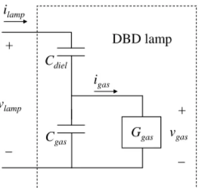
An equivalent circuit for a DBD apparatus [1]-[5], which has proven to be very representative in the case of excimer lamps, is reminded on Fig. 1.
Fig. 1 equivalent circuit model of the excilamp.
The capacitors are, as usual, on the one hand the capacitance of the dielectric walls (Cdiel) and, on the second hand, the capacitance of the gas (Cgas). This capacitor is the main electric characteristic of the gas, as long as the discharge remains in OFF state; Ggas is the conductance of the gas: it describes the behavior of the latter when the discharge is in
ON state; furthermore, the voltage across the gas vgas being the state variable which causally defines the state (ON, OFF)
of the system, Ggas is the adequate choice to evaluate the current flowing in the gas, igas. A good approximation of the
behavior of Ggas has shown to be given by equation (1).
gas pro gas ext gas th gen gas
i
K
G
K
V
v
V
K
t
G
1exp
1
d
d
(1)The 3 terms of the right hand side are respectively associated with three phenomena: breakdown, which occurs when vgas reaches the threshold voltage Vth,
the extinction of the created species (Kext controlling the extinction rate),
the creation of the excited species, which is assumed to be proportional to the magnitude of the | igas | current.
The identification of the parameters of the model is achieved by means of an automated method: the set of values (Kgen,
Vth,DV, Kext, Kpro introduced in equation (1)) is iteratively adjusted so as to obtain a good agreement between
experimental and simulated waveforms; this approach and its implementation are detailed in [6]. The parameters, corresponding to the 60W XeCl excilamp used for experimentations are given in appendix. The behavior of the circuit of Fig. 1 is driven by following electric differential equations (2), (3):
i
dt
C
v
v
lamp diel lamp gas1
(2) gas gas gasG
v
i
(3)Once the parameters of the model are identified, Ggas, vgas and igas, which are non-measurable quantities, are computed
according to measurements realized with a classical sinusoidal voltage supply and using equations (1), together with (2) and (3).
To note that the formulation of these state equations favors the expression of the actual causality chain between the physical quantities: derivatives are avoided and ilamp current in the lamp clearly appears to be the origin of the behavior of
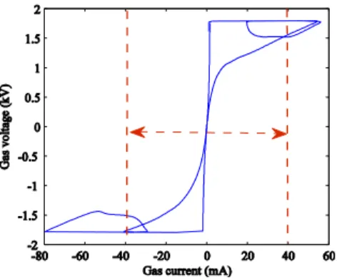
the whole system. Concerning the lamp used for experimentations, the obtained (igas - vgas) characteristic of the gas is
presented on Fig. 2. ilamp vgas Ggas Cdiel Cgas + _ igas DBD lamp vlamp + _
Fig. 2 (igas - vgas) characteristic of the gas
This hysteretic form is characterized by the voltage plateau, with a value very near to the Vth threshold voltage. When the gas is in ON state, the operating point remains on this plateau: the gas voltage vgas remains constant, in a quite large
domain for the igas current values. Thus, the instantaneous power transferred from the supply to the gas, being the
gas gas
v
i
product, is directly controlled by the igas current. As appears on Fig. 1, the generator supplies the ilamp current,which will be shown later very similar to igas, except when the discharge is OFF.
3. CURRENT CONTROLLED SUPPLY FOR EXCILAMPS
According to the conclusions of the previous section, the mostly desirable characteristic of a power supply for a DBD excilamp is the ability of controlling the current which circulates in the lamp. Additionally, the electric generator must supply a current, which mean value is zero, at a timescale corresponding to the operating period, because of the capacitive characteristic of the lamp.
Fig. 3 current controlled power supply
In this scope, several topologies have been considered [9]. The circuit of Fig. 3 presents one of them, with a circuit which permits:
to invert the sign of the current in the lamp after each half period, thanks to the switches S1 and S1’, which both are associated with one of the primary windings of the transformer (oppositely pointed);
to control the amount of energy which is supplied to the lamp during each half operating period, thanks to switch S0.
3.1 Operation
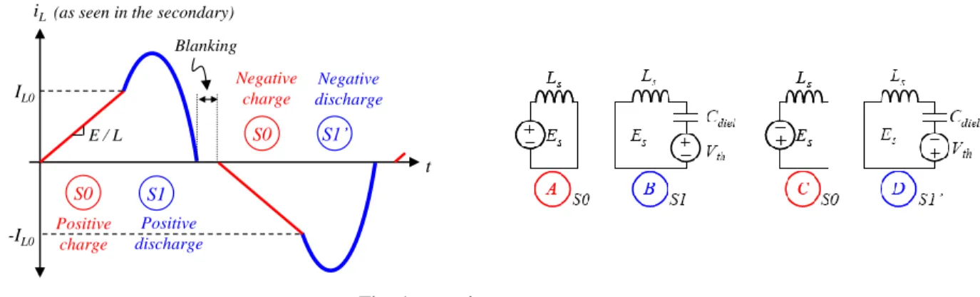
Fig. 4 presents the idealized expected waveforms (current in the L inductance – red and blue lines- and current in the lamp – blue line), and the operating sequences, according to the states of the switches of the converter. These plots are obtained with a circuit simulation program [10], [11]: the step-up transformer is supposed ideal (ratio : n) and the lamp is sketched, according to the characteristic of Fig. 2, as a ±Vth voltage source in series with the dielectric capacitor Cdiel. A very important feature of this converter appears on Fig. 4: the duration of sequences (A) and (C), during which the energy is stored in the L inductance (1/2 L.IL0²) permits to control the amount of energy which is injected into the lamp
during each half period. The stored energy is transferred through the transformer into the lamp during the oscillating sequences (B) and (D), involving L and Cdiel.
The duration of the sequences (B) and (D), tdischarge, is defined by the values of Cdiel, L, n (step-up ratio of the
thyristors). A blanking time interval, added between sequences (B) and (C) on the one hand and between (D) and (A) on the second hand, is introduced to adjust the relaxation time interval between two current pulses in the lamp.
t IL0 E / L S0 S1 iL -IL0 Blanking S0 S1’ Positive charge Negative charge Negative discharge Positive discharge (as seen in the secondary)
Fig. 4 operating sequences
It additionally defines, with tcharge which is the duration of sequences (A) and (C), the operating period of the converter:
switch blanking e disch e ch
t
t
f
t
T
(
arg
arg
)
2
1
/
(4)The IL0 value of the current in L at the end of sequences (A) and (C) – equation (5) –, defined by the controlled turn-on of
either S1 or S1’ to start the (B) or (D) sequences, is a direct method of controlling the power transferred to the lamp as expressed in equation (6), where fswitch denotes the operating frequency of the supply.
L
t
E
I
L0
charge/
(5)
2 02
1
2
switch L lampf
L
I
P
(6)3.2 Design and control considerations
Concerning the design of such a supply, one should mention, that the 3 switches of the converter require thyristor-like operating characteristics (unidirectional current in ON state, bidirectional voltage in OFF state with controlled turn-on and spontaneous turn-off). The usual operating frequencies of classical devices are not compatible with the frequency expected in the considered application (some kHz). So, a synthesized function based on a power MOSFET, in series with a high voltage fast diode, associated with an electronic management circuit has been especially studied and designed. Concerning the step-up transformer, a critical point for the set-up of such a supply, the design of the latter is a very important issue: indeed, the parasitic parameters of the windings (especially the high voltage one) have a critical effect on the quality of the waveforms and of the operating conditions. The magnetizing inductance must have a large enough value to avoid current flow in the lamp during sequences (A) and (C). Leakage inductances should be minimized to avoid high frequency oscillations during sequences (B) and (D). As for the capacitance of the secondary winding, it derives a percentage of the current in the lamp and should be minimized as well.
As introduced by equations (4) to (6), the proposed power supply offers several degrees of freedom (DOF) to achieve the control of the power transfer:
tcharge permits to choose the values of current (IL0/n) which will be injected in the lamp; it also defines the energy
transferred into the lamp during the next pulse.
tdischarge is not directly controllable and depends upon the value of IL0.
tblanking is adjustable and defines the duration of the relaxation time interval (no current injected into the lamp) and
contributes to the definition of the operating frequency.
In the experimental setup, these DOF are managed by means of a DSP-FPGA based control unit, which accurately defines all the events through the firing orders of each power switch and offers possible transient analysis and time domain measurements.
4. PERFORMANCES AND CHARACTERISTICS OF THE UV PRODUCTION
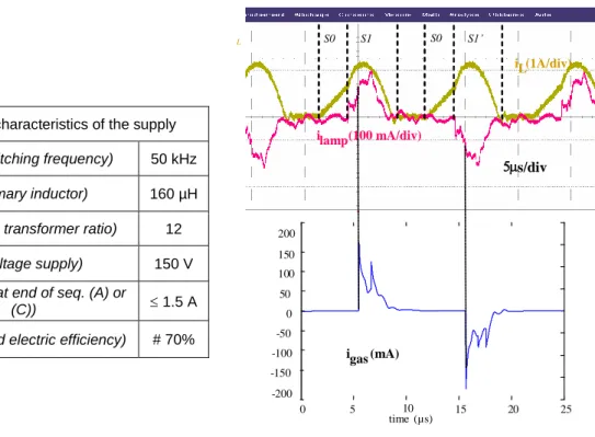
4.1 Electric behavior of the supplyA prototype of the proposed supply has been implemented (the main characteristics are summarized in the following table); Fig. 5 shows the current measured in the L inductance, and the ilamp current in the lamp. These quantities appear to
be very similar to the theoretical ones; higher frequencies oscillations, which appear on the ilamp signal, are caused by the
mentioned parasitic elements of the step-up transformer. On the basis of the model described in section 2, non-measurable quantities are calculable; the computed current flowing through the gas, igas, is also presented.
Electric characteristics of the supply fswitch (switching frequency) 50 kHz
L (primary inductor) 160 µH N (step-up transformer ratio) 12
E (voltage supply) 150 V
IL0 (current at end of seq. (A) or
(C)) 1.5 A
(measured electric efficiency) # 70%
Fig. 5 Main characteristics of the supply; measured currents: iL (brown) and ilamp (red) – computed current igas (blue)
4.2 UV production
Associated to the power supply, an optical apparatus has also been developed: it offers time-resolved (with synchronization on the control signals of the power supply) and mean measurements of the produced light, both in the visible and UV domains [12]. The comparison between the shapes of the instantaneous UV power level and the computed igas current is proposed on Fig. 6(a).
Fig. 6 (a) shapes of the measured instantaneous UV power (blue) compared to the computed igas current (black) -
(b) instantaneous control of the ilamp current - (c) UV production controlled by the power supply.
iL ilamp ilamp UV
-200 -150 -100 -50 L
i lamp (100 mA/div) iL(1A/div) S0 S1 S0 S1’ s/div 0 5 10 15 20 25 0 50 100 150 200 time(µs) i gas (mA) 0 5 10 15 20 -300 -200 -100 0 100 200 300 temps ( igaz (mA) time (µs) UV (A.U.) igas(mA)
Thanks to the synchronization between the power supply and the optical measurements, the similarity of the waveforms is stated. Several similar measurements, with different igas pulse durations, have been realized and give identical
conclusions: the UV production is very tightly correlated to the igas current in the gas, and any changes in the latter (by
mean of one of the DOF of the supply) is immediately followed by the same change on the UV. The timescales concerning the use of this property for UV emission control purpose start from half the operating period of the converter. Fig. 6(b) shows the capability of the supply to change the current in the lamp at the half-period timescale. Fig. 6(c) exhibits the capability of the supply to define the UV level by mean of the controllable ilamp current, even in transient
conditions.
The quality of the produced UV has been checked with different levels of power injection (controlled by mean of the
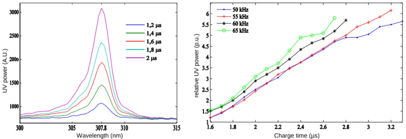
tcharge duration): Fig. 7(a) proves that the spectral quality of the radiation of the lamp is not affected by the transferred
power.
Fig. 7 (a) power distribution of the produced UV, for different power injection levels - (b) Control of the radiation of the lamp with DOFs of the power supply (frequency and injected energy): relative mean UV power, vs tcharge, for several
operating frequencies
Considering the mean values of the UV power (measured with a 308 nm radiometer) the DOFs of the supply have been used to study the correlation between the relative UV power and the injected power, for several operating frequencies. Fig. 7(b) shows the UV power increase:
with the tcharge duration, which defines the energy sent to the lamp – see equation (6) – (theoretically, according to
equations (5) and (6), with a quadratic shape),
for a given level of injected electric power, with the switching frequency (which is proportional to the injected electric power – see equation (6)).
One can notice that the lower curve at 50 kHz remains very near to the one at 55 kHz. This can be interpreted as better conversion, from electrical to optical power (higher efficiency), of the lamp at 50 kHz. The last result is very interesting, letting imagine that the current-mode power supply can be used to identify the optimal operating frequency of the lamp.
5. CONCLUSION
The concept of a current-controlled static converter has been selected, to control the power transfer to a DBD lamp, on the basis of causality criteria. The proposed topology has shown its capability to control the current and the power injected in the lamp at each half operating period.
An UV optical measurement apparatus, synchronized with the power supply has been associated with the experimental set-up: it has highlighted the fact that the UV production is directly controlled by the current which actually flows into the gas – this non observable current is controllable by mean of the current which is injected in the lamp.
The proposed static converter offers two main degrees of freedom to define the operating conditions of the system: the injected power level at each half period and the frequency. These DOF have been explored and the UV emission has shown tightly correlated to the electric power. Specific behavior (depending for instance upon the operating frequency)
U V p o w e r (A .U .)
Wavelength (nm) Charge time (µs)
re la ti v e U V p o w e r (p .u .)
has been observed and let consider that the power supply presented in this paper can be useful for further studies, carried by plasma physicist, in order to define the optimal operating parameters of a DBD lamp.
AKNOWLEDGEMENT
The authors thank Dermoptics (Quantel Group) for their support in providing their patented lamp for the experimental part of the work. This study is in the framework of a French Colombian cooperation, for which a support in ECOS program (ECOS-Nord/COLCIENCIAS-ICETEX) has been applied.
APPENDIX: PARAMETERS OF 60W XE-CL EXCILAMP
The parameters of the 60W excilamp used for experimentations have been identified, as described in section 2. The following table summarizes the values introduced in equation (1) and Fig. 1.
Vth (V) ΔV (V) Kgen (Ω·s-1) Kext (s-1) Kpro (V-1·s-1) Cdiel (pF) Cgas (pF)
initial guess 1500 20 130 2,7 x 10⁶ 1835 39,81 13,07
final result 1800 2,9 2 x 10⁴ 1 x 10⁶ 100 40,03 13,87
REFERENCES
[1] S. Bhosle, G. Zissis, J.J. Damelincourt, A. Capdevila, K. Gupta, F.P. Dawson, V.F. Tarasenko, "Implementation of
an efficiency indicator in an electrical modeling of a Dielectric Barrier Discharge Lamp", IEEE/IAS 41th Annual
Meeting - october 8th-12th, 2006, Tampa (USA)
[2] E.A. Sosnin, M.V. Erofeev, V.F. Tarasenko, D.V. Shits “Capacitive Discharge Excilamps”. Instruments and Experimental Techniques, 2002, Vol. 45, No. 6, pp. 838-839
[3] M.I. Lomaev, E.A. Sosnin, V.F. Tarasenko, D.V. Shits, V.S. Skakun, M.V. Erofeev, A.A. Lisenko. ”Capacitive
and Barrier Discharge Excilamps and Their Applications (Review)”. Instruments and Experimental Techniques,
2006, Vol. 49, No. 5, pp. 595-616
[4] S. Vongphouthone, H. Piquet, H. Foch. “Model of the homogeneous electrical discharge”. Eur. Phys. Journal AP 15, 2001, 123-133
[5] U. Kogelschatz, "Dielectric-barrier Discharges: Their History, Discharge Physics, and Industrial Applications", Plasma Chemistry and Plasma Processing, Vol. 23, No. 1, March 2003
[6] Oda, H. Sugawara, Y. Sakai, H. Akashi, "Estimation of the light output power and efficiency of Xe barrier
discharge excimer lamps using a one-dimensional fluid model for various voltage waveforms", J. Phys. D: Appl.
Phys. 33 (2000), 1507-1513
[7] R.P. Mildren, R.J. Carman, "Enhanced performance of a dielectric barrier discharge lamp using short-pulsed
excitation", J. Phys. D: Appl. Phys. 34 (2001), L1-L6
[8] R. Díez, J.-P. Salanne, H. Piquet, S. Bhosle and G. Zissis, "Predictive model of a DBD lamp for power supply
design and method for the automatic identification of its parameters", Eur. Phys. J. Appl. Phys. 37, 307-313
(2007)
[9] R. Díez, H. Piquet, S. Bhosle, J.M. Blaquière and N. Roux, “Design of a Current Converter for the Study of the
UV Emission in DBD Excilamps” in Proc. of the IEEE-ISIE, vol.1, 62-67, 2008.
[10] Powersym Inc. 2005 PSIM User’s guide web: http://www.powersimtech.com/
[11] Synopsys 2005 Saber MAST Language Reference manual web : http://www.synopsys.com
[12] Sounil Bhosle, Hubert Piquet, Doanh Le Thanh, Mahammat Djibrillah, Ahmad Nazri Dagang, Georges Zissis,
High Speed UV Imaging of a Dielectric Barrier Discharge Excilamp Pumped by Various Waveforms, Proc. of the