Publisher’s version / Version de l'éditeur:
Vous avez des questions? Nous pouvons vous aider. Pour communiquer directement avec un auteur, consultez la première page de la revue dans laquelle son article a été publié afin de trouver ses coordonnées. Si vous n’arrivez pas à les repérer, communiquez avec nous à PublicationsArchive-ArchivesPublications@nrc-cnrc.gc.ca.
Questions? Contact the NRC Publications Archive team at
PublicationsArchive-ArchivesPublications@nrc-cnrc.gc.ca. If you wish to email the authors directly, please see the first page of the publication for their contact information.
https://publications-cnrc.canada.ca/fra/droits
L’accès à ce site Web et l’utilisation de son contenu sont assujettis aux conditions présentées dans le site LISEZ CES CONDITIONS ATTENTIVEMENT AVANT D’UTILISER CE SITE WEB.
Paper (National Research Council of Canada. Division of Building Research); no.
DBR-P-1352, 1985
READ THESE TERMS AND CONDITIONS CAREFULLY BEFORE USING THIS WEBSITE. https://nrc-publications.canada.ca/eng/copyright
NRC Publications Archive Record / Notice des Archives des publications du CNRC :
https://nrc-publications.canada.ca/eng/view/object/?id=271176ee-5e5c-4ee4-a3ef-248e2196171c
https://publications-cnrc.canada.ca/fra/voir/objet/?id=271176ee-5e5c-4ee4-a3ef-248e2196171c
NRC Publications Archive
Archives des publications du CNRC
This publication could be one of several versions: author’s original, accepted manuscript or the publisher’s version. / La version de cette publication peut être l’une des suivantes : la version prépublication de l’auteur, la version acceptée du manuscrit ou la version de l’éditeur.
For the publisher’s version, please access the DOI link below./ Pour consulter la version de l’éditeur, utilisez le lien DOI ci-dessous.
https://doi.org/10.4224/40001794
Access and use of this website and the material on it are subject to the Terms and Conditions set forth at
Fire performance of reinforced concrete columns
*
I National Research Conbellnatlonal
Council Canada de recherche8Canada
Division des
Building Research recherches en batiment - -
Fire Performance of Reinforced
Concrete Columns
by T.T. Lie and T.D. Lin
ANALYZED
Reprinted from"Fire Safety: Science and Engineering" ASTM, STP 882,1985 p. 176-205 (DBR Paper No. 1352) Price $3.00 NRCC 25351 NRC
-
CISTIBbDG. RES.
L I B R A R Y
us-
0s-
1
~ I ~ ~ ~ ~ T H ~ Q w E
-,:ch.
BStim.
I
-
IOSTDBRIDRB
Canad3
-6 3 8796L
On
a effectue des Btudes experimentales et theoriques en vue d'blaborer des methodes generales permettant de determiner laresistance au feu de poteaux de beton arme. Ce document fait
&at des conclusions de la premiere phase de 116tude, au cours
de laquelle douze poteaux ont fait l'objet d'essais. Parmi les
variables Btudiees, ce sont la charge, la dimension des sections et le type de granulat qui ont eu le plus d'impact sur
la resistance au feu des poteaux. Dans les conditions
btudiges, l'influence du degre d1humiditB du bbton s'est revelee negligeable. Les temperatures, les deformations et la
resistance au feu des poteaux, calculees il l'aide d'un modele
mathBmatique, correspondaient ggneralement 3 celles qui ont kt6
mesc1r6es. On donne un apersu des variables qui seront
examinees dans la seconde phase de 1'6tude. -
C o p y r ~ g h t
ism
T.
, T ~ ~ Iand
T~~~ D.
~ i American S o c t e t y f o r T e s t i n g a n d Materials ~ 2 1 9 1 6 R a c e S t r e e t . Philadelphia, PA 19 1031985
:ire Performance of Reinforced
>oncrete Columns
REFERENCE: Lie. T. T. and Lin, T. D.. bbFire Performance of Reinforced Concrete Columns,'' Fire Sulery: Science u ~ r d Engineerirrg. ASTM STP 882, T. 2. Hamathy. Ed.. American Society for Testing and Materials. Philadelphia. 1985. pp. 176-205. ABSTRACT: To develop general methods for the prediction of the fire resistance of rein- forced concrete columns, experimental and theoretical studies were carried out. Results obtained in the first phase of the study, which involved the testing of twelve columns, are given. Of the variables studied in this phase, load, cross-section size, and type of aggre- gate had the largest influence on the fire resistance of the columns. The influence of con- crete moisture content was, within the range studied, insignificant. Column tempera- tures. deformations, and fire resistance, calculated using a mathematical model, were in good agreement with those measured. The variables that will be studied in a second phase study are outlined.
KEY WORDS: fire tests, calculation, reinforced concrete, columns, temperature, defor- mation. failure. load, cross section, aggregate, moisture
omemlatun
Specific heat, J/kg°C
Compressive strength of concrete at temperature T, MPa Cylinder strength of concrete at temperature T,sMPa ,
,
Cylinder strength of concrete at room temperature, MPa Strength of steel at temperature T, MPaYield strength of steel at room temperature, MPa
I Coefficient of heat transfer at fire-exposed surface, W/mZOC
: Thermal conductivity, W/m°C
:
Effective length factorResearch Officer. Division of Building Research. National Research Council of Canada. Ot- va. Canada.
'Principal R w a r c h Engineer. Construction Technology Laboratories. Portland Cement Asso-. tion, Skokie, IL 60077.
176
LIE AND LIN ON REINFORCED CONCRETE COLUMNS 17
L
Unsupported length of column, m P PointT Temperature, OC
x Coordinate
y Lateral deflection of column at midheight, m
z Coordinate
Greek Letters
Coefficient of thermal expansion Increment
Mesh width, m Emissivity, strain, m Heat of vaporization, J/kg
Density (kg/mJ), radius of curvature (m) Stefan-Boltzmann constant, W/m2
K4
Time, hConcentration of moisture (fraction of volume) Curvature of column at midheight, m-'
Subscripts 0 C '
f
m , M max min n,N
LR
P ST
W At room temperature Of concrete Of the fireAt the points, m , M in column Maximum
Minimum
At the points n,
N in a row
Left of the x-axisRight of the x-axis
Pertaining to proportional stress-strain relation
Of
steelPertaining to temperature Of water
Superscripts
Studies on reinforced concrete columns were started a few years ago for t h purpose of updating existing fire resistance ratings for these columns.
'Th
ratings in most North American building codes were based on test results otadopted a conservatively based rational method for the determitiation of the firc rcsistaticc of rcinforccd concrctc columns. Over the years. design procc- dures and the safety fltctor for these columns have changed. Thus. there is a
need for the rcvision of present ratings.
In a cooperative effort between the National Research Council of Canada and the 1'ortl;tnd Ccmcnt Association, a niultiphasc progrnni has hccn worked out for the study of the behavior of full-size rci~iforcctl concrcte columns exposed to firc. Its main objectives arc:
I. To gcncratc firc resistance data o n reinforced concrctc colunins dc- signed in accordance with current Building Code Rcquirc~iicnts for Rcin- forced Concrete (ACI 318-77)' or the Cotlc for the Design of Co~icrctc Struc- tures for Buildings (CSA-CAN A23.3-M77)."
2. '1-0 develop gcncral methods for ~ l i c calculation of the firc resistance of concrete coli~tiins and walls for a wide range of applications.
Program
In the joint study program, theoretical as well as experimental studies will he carried out. A newly constructed colunin test furnace is used for the cxperi- mental studies. which are also intended for validation of a recently developed mathematical model for the calculation of fire rcsistancc of reinforced con- crete columns 11
I.
The study variables in the program include the following:I . Load intensity. 2. Eccentricity of loading. 3. Fire exposure intensity. 4. Cross section of column or wall. 5. Column height.
h. Thickness of concrete cover. 7. Amount of steel.
8. Type of aggregate. 9. Strength of concrcte.
10. Moisturc content of concrcte. I I . Kcstrailling cffc.;t.
12. hssihly. ~tnsyninictrical fire exposure.
This paper deals with the first phasc of the program, which involved the testing o f twelve columns. The columns were designed and manufactured by Portland Cement Association, in Skokic, Illinois. The spccimcns were trans- ported to the fire research laboratories of the N;ttional Research Council of
Canada, where the fire tests were conductctl. The factors studicti in this phasc 'American ('oncrctc In\tilt~te.
LIE AND LIN ON REINFORCED CONCRETE COLUMNS 179
were the temperatures attained in different section sizes by the concrete and reinforcing steel. and the influence of load. moisture. and aggregate on the fire resistance of the colunins.
Test Specimens
In the first phase of the study program, a series of twelve square reinforced concrete columns were fabricated and tested. Ten of the columns had a cross section of 305 by 305 nim ( 1 2 by 12 in.). one of 203 by 203 mm ( 8 by 8 in.), and one of 406 by 406 mm (16 by 16 in.). All columns were 3810 mm (12 ft 6 in.) long. Three specimens were made with carbonate aggregate and nine with siliceous. The average 28-day concrete strengths were 33.8 MPa (4898 psi) for carbonate aggregate concrete and 34.2 MPa (4958 psi) for siliceous aggregate concrete.
Table 1 gives details of cross section. the type of aggregate used in the con- crete. the relative humidity measured in the center of the column at the time of the test, and the concrete cylinder strength measured at different times.
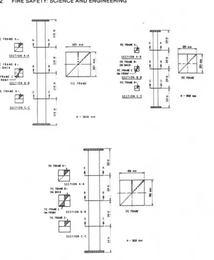
For the steel reinforcement, deformed 25M (No. 8) longitudinal reinforcing bars and 10M (No. 3) ties were used. Their location in the column is shown in Fig. 1. The yield strength of the 2SM bars was 443.7 MPa (64.3 ksi) and that of the 10M bars 426 MPa (61.8 ksi).
Chromel-Alumel thermocouples were used to measure concrete and steel temperatures in the column. The thermocouples in the concrete were ar- ranged to measure temperatures at various locations: at one-quarter height, a t midheight, and at three-quarter height of the column. The location of the thermocouples in the concrete and on the steel are given in Figs. 1 and 2.
Further details of the specimens are given in Ref I . Calculation Procedure
The calculation of the fire performance of the columns is carried out in various steps. It involves the calculation of the temperatures in the column and its deformations and strength during the exposure to fire.
Temperatures of Column
The column temperatures are calculated by a finite difference method 121. This method has been previously applied to the calculation of temperatures in square reinforced concrete columns 131. Because the method of deriving the heat transfer equations and of calculating the temperatures is described in detail in those studies. it will not be discussed here; only the equations used for calculation of the column temperatures and information not dealt with in previous studies will be given.
TABLE I -Derails cottcerning first phase column test specimens [cyss sections 305 b.v 305 mm
112 by 12 in.) unless otherwise noted].
Moisture Compressive Strength
Condition of of Cylinders
Specimen at
Middepth at At 28 Days At Test Date'
Specimen Cast Date Test Date Test Date"
No. (yr.. mo.. day) (p.. mo., day) (% RH) MPa (Psi) MPa (Psi)
not mea- sured 37.3 (5402) 36.6 (5305) 34.2 (4961) 34.2 (4952) 35.9 (5199) 34.5 (4996) 35.8 (5190) 42.6 (6172) 38.8 (5633) 42.6 (6172) 42.1 (6109) 36.8 (5332) 35.4 (5129) 34.2 (4952) 35.4 (5138) 39.7 (5757) 37.0 (5359)
"Cross section 406 by 406 mm (16 by 16 in.). hCross section 203 by 203 mm (8 by 8 in.). '-Results of one or more cylinder tests are given.
"See text for method of conditioning. For relation between relative humidity in center of concrete and its moisture content. see ASTM E 119-79.
column is subdivided into a number of elements, arranged in a triangular network (Fig. 3). The elements are square inside the column and triangular at the surface. For the inside elements, the temperature at the center is taken as representative of the entire element. For the triangular surface elements, the representative points are located on the center of each hypotenuse.
Because only columns with square cross sections (and four axes of symme- try) will be considered, it is possible to calculate the temperature distribution in only one eighth of the cross-sectional area of the column. As illustrated in
TIC 1SAMC 1- ON 1 A C 1 TIC f t A Y t c 0 " f t O " 1
9
I C C l l O N 8 . 8 u I I ! S C C l l O N A-A 1% n ) L I b cm M a S C C I I O N 0.8 TIC 1 R F m h&
SCC11ON C - CFIG. 2-Luyout of thermocouple frames.
Fig. 3, in an x-z coordinate system, a point
P,,,.,
has the coordinates x =(rn
-
l ) A ( / f i a n d z = (n-
l ) A ( / f iEquations for the Fire/Concrete Boundary-It will be assumed that the columns are exposed on all sides to the heat of a fire whose temperature course follows that of the standard fire described in ASTM Methods for Fire
Tests of Building Construction and Materials
(E
119-83). This temperatureLIE AND LIN ON REINFORCED CONCRETE COLUMNS
183
FIG. 3-Trio~rgtrlur ttetuwrk ojekn~ertrs in o one-eighr secriort of column.
where
r = the time in hours, and
T i = the fire temperature in "C at the time r = j a r .
The temperature rise in each element can be derived by determining the heat balance for them. For a surface element, the temperature at a time 7 =
( j
+
1 )AT is given by the expression 2Ar T,;;l = TI,,,+
[(prcc).',,,,
+
~*.c*.6.{,,,1 ( A t ) ZEquations for Inside the Concrete-For the elements in the concrete, the temperature rise a t the time r = ( j
+
1)Ar is given byAuxiliary Equations-To calculate the temperatures of the elements along the lines of symmetry A-Cand B-C, the temperature has to satisfy the follow- ing symmetry conditions
Line A-C = TJ+l
M.3
Line B-C
In order to ensure that any error existing in the solution at some time level will not be amplified in subsequent calculations, a stability criterion has to be satisfied which, for a selected value of At, limits the maximum of the time
step (AT). Following the method described in Ref 4, it can be derived that for
the fire-exposed column the criterion of stability is most restrictive along the
line m
+
1, between fire and concrete. It is given by the conditionwhere the maximum value of the coefficient of heat transfer during exposure
to the standard fire (h,,) is approximately 3 X lo6 J/m2 h°C (147 Btu/ft2
h°F).
Effect of Moisture-The effect of moisture is taken into account by assum-
ing that in each element the moisture starts to evaporate when the tempera- ture of the element reaches 100°C (212OF). During the period of evaporation, all the heat supplied to an element is used for evaporation of the moisture, until the element is dry. Migration of moisture is not taken into account.
From the heat balance equation. the moisture concentration in an element at the fire/concrete boundary at the time r = ( , j
+
I )AT is given bySimilarly, the moisture concentration in an element inside the concrete at the time r = ( j
+
1)Ar is given byWith the aid of Eqs 1 to 8 and the relevant material properties given in the Appendix, the temperature distribution in the column and on its surface can be calculated for any time [ r = ( j
+
1)Ar) if the temperature distribution at the time j A r is known. Starting from a temperature of 20°C (68OF). the tem- perature history of the column can be calculated by repeated application of Eqs 1 to 8.Calculation of Strength during Fire
Transformation into Square Network-To simplify the calculation of the deformations and stresses in the column, the triangular network is trans- formed into a square network. In Fig. 4 a quarter section of this network. consisting of square elements arranged parallel to the x- and z-axis of the section, are shown. The width of each element of this network is
AEIJZ.
The temperatures, deformations, and stresses of each element are represented by those of the center of the element. The temperature at the center of each ele-FIG. I-Syrruru ~ r e t n v ~ r k o/ r l u ~ ~ r c ~ i ~ t s i ~ r u qrrurtvr sucrb~rr a! c ~ r ~ l r t r ~ ~ n .
ment is obtained by averaging the temperatures of the elements in the trian- gular network according to the relation
where the subrcripts "square" and "triangular" refer to the elements of the square and triangular network.
During exposure to fire. the strength of the column decreases with the du- ration of exposure. The strength of the column can be calculated by a method based on a load-deflection analysis which in turn is based on a stress-strain analysis of cross sections 151. In this method. the columns. which are fixed at the ends during the tests. are idealized as pin-ended columns of reduced length KL. in which K was assumed to be 0.6 (Fig. 5 ) . The load on the test columns i \ intended to be concentric. To represent imperfections in the columns. an initial deflection y,, = 2.5 nim (0.1 in.) is assumed.
The curvature of the column is assumed to vary from zero ar pin-end to midheight according to a straight line relation. as illustrated in Fig. 5. For such a relation the deflection at midheight ( y ) . in terms of the curvature ( y ) of the column at this height, can be given by
LIE AND LIN ON REINFORCED CONCRETE COLUMNS 187
1 O C F L C C T I O N C u R y ~ r ~ g (
$T/tj-+
112 I I-
-
I7 '
FIG. 5-Assrmtrd loud-deflection ur#a!vsis.
For any given curvature ( x ) and thus for any given deflection at midheight, the axial strain is varied until the internal moment at the midsection is in equilibrium with the applied moment given by the product of load and total deflection. In this way a load deflection curve can be calculated for specific times during the exposure to fire. From these curves the strength of the column (its maximum load-carrying capacity) can be determined for each time. In the calculation of column strength, the following assumptions were made:
1. The properties of the concrete and steel are as given in the Appendix and later in this section.
2. The influence of the presence of reinforcing steel on the temperature may be neglected. Thus the column, from a thermal point of view, may be treated as consisting entirely of concrete. The temperature of the steel is as- sumed to be equal to the temperature in the column section at the location of the center of the steel.
3. Concrete has no tensile strength. 4. Plane sections remain plane.
5. Initial strains in the column before the exposure to fire consist of free shrinkage of the concrete and creep. Because mortar was inserted at the top to make good contact between the concrete and the steel end plate, the initial shrinkage will be assumed to be negligible.
The tests of the columns were started after a preloading period of about I
~
h. The shortening of the column due to creep in this period is assumed to be negligible.Based on these assumptions, the change of column strength during the ex- posure to fire was calculated. In the calculations the square network shown in Fig. 4 was used. Because the strains and stresses of the elements are not sym- metrical with respect to thex-axis, the calculations of the strains and stresses were performed for both the network shown and an identical network at the
I
left of the x-axis. Thc force and moment in the section were obtained by add- ing, respectively, thc forces carried by each element and the moments con- tributed by them.
The equations used in the calculations of the strength of the column during the exposure to fire are given below.
Eqtrtrriotrs~/hr rht, S1rt4-From the assumption that plane sections remain plane. the strain in thc reinforcing steel is equal to the axial strain of the column ( t ) and the strain due to bending of the column ( z , / p ) . where z , is the horizontal distance of the reinforcing steel bar to the vertical plane through the x-axis of thc section of the column and p is the radius of curvature. The strain causing stress. however. is determined as the difference between this strain and the free strain [ ( t T ) ,
1
that would take place due to thermal expan- sion of the stecl. For the steel at the right of the x-axis, this strain is given byFor the steel elements at the left of the x-axis, the strain [ ( E , ) ~ ,
I
is given byThe stresses in the elements of the network are calculated using stress- strain relations derived from data provided by lngberg and Sale 161 and Wit- teveen, Twilt, and Bylaard 171. These relations include the effect of creep at elevated temperatures and were obtained at heating rates approximately those that occur in a fire in actual practice. The relations have been general-
ized for other structural steels by assuming that, for a given temperature, the t curves are the same for all steels, but the stress below which the stress-strain
relation is linear is proportional to the yield strength of the steel. The equa- tions that describe the relation between the stress in the steel ( J , . ) , the strain
( t , ) , and the temperature of the steel ( T ) are as follows (Fig. 6) for
where
LIE AND LIN ON REINFORCED CONCRETE COLUMNS 189 100
-
I00 rf
mn o r /-
-
ZOO 1-
M I . C 100 0 0 P I 0 P I 0 01 1 0, 11, S I R A l " a ,FIG. 6-Stress-struirl curves for the reinforcing steel at various temperatures (f,. = 443 MPa).
for
es
>
Epf ( T . 0.001)
f l , = o . ~ l e,
+
f [ T , (q-
e p+
0.001)]-
f ( T , 0.001) (16)The value of 0.001 was selected as the proportional limit of a standard steel of 250 MPa (36 ksi) strength. With the aid of Eqs 10 to 16, the stresses at
midheight in the steel can be calculated for any value of the axial strain ( e ) ,
curvature ( f / p ) , and temperature
(T).
From these stresses the load that thesteel carries and the contribution of the steel to the moments can be derived. Equations for the Concrete-In the same way as for steel, the strain in the
concrete causing stress for elements at the right of the x-axis (Fig.
4)
can begiven by
= -(eTIc
+
e+
5
P (17)
and for elements at the left of the x-axis by
=c
= - ( E T ) ~
+
e-
-
P (18)
where
( e ~ ) ~
=
free strain due to thermal expansion of the concrete,t
=
axial strain of the column,z,
=
horizontal distance of the center of the element to the vertical planethrough the x-axis of the column section, and
The stresses in the elements are calculated using stress-strain relations
based on the work of Ritter [8] and Hognestad [ 9 ] . These relations have been
slightly modified to take into account the creep of concrete at elevated tem- peratures. The modifications are based on results of work by Schneider and Haksever [ l o ] and consist of a movement of the maxima in the stress-strain curves to higher strains with higher temperatures. These curves are shown in
Fig. 7 for a concrete with a cylinder strength of 35 MPa
(5
ksi). The equationsthat describe these curves are as follows for for Ec
>
emaa where f: =fk
ifT
Q 450°C S l a A 1 1 . * cLIE AND LIN ON REINFORCED CONCRETE COLUMNS 191
In these equations
/;. = con~pressive strength of concrete a t temperature T ,
,t;l = cylinder strength of concrete at temperature T.
j;:, = cylinder strength of concrete at 20°C (68°F).
c, = strain of the concrete. and
c,,,, = strain corresponding to maximum stress.
With the aid of the Eqs 17 to 23. the stresses in each of the concrete ele- ments a t midsection can be calculated for any value of the axial strain ( 6 ) and
curvature ( 1 / p ) . From these stresses the load that the concrete carries and the contribution of the concrete to the moments can be derived.
Test Conditions and Procedure
The tests were carried out by exposing the columns to heat in a furnace specially built for this purpose.
heh heat
input into the test furnace was con- trolled in such a way that the average temperature followed as closely as possi- ble the standard temperature/tinle curve given by Eq 1. The instrumentation and characteristics of the furnace are described in detail in Ref 11.Several of the columns were tested under a load, which was concentric. The loads were applied about one hour prior to the test. The columns were fixed a t the ends.
On the date of testing, the relative humidity in the center of the concrete and the cylinder strength of the concrete were measured. The measured val- ues are given in Table 1. Four columns, tested in near oven-dry condition, were kiln-dried at about 93°C (200°F) and 0 to 5% relative humidity. After the designated moisture condition was reached, the columns were wrapped in plastic to prevent change in their moisture content. The other columns were conditioned in a n atmosphere controlled a t 21 to 24°C and 30 to 40% relative humidity and later kept for at least six months in an atmosphere of about
20°C and 50 to 75% relative humidity, prior to testing.
During the test, measurements were made of the temperatures of the con- crete and steel in the column a t the locations described earlier. The axial strain of those columns that were tested under a load was also measured. These columns were considered to have failed. and the test was terminated, when the hydraulic jack, which has a maximum speed of 76 mm/min (3 in./ min), could no longer maintain the applied load. Unloaded columns, which were tested to obtain information on the temperature history in the column. were exposed to fire for 3 to 5 h, depending on their size. The duration of the various tests and the loads that were applied are given in Table 2.
TABLE 2-Loud und per/ormunce oof test columns [cross section 305 by 305 rnrn I12 by I2 in.) unless or hem is^ indicutedl.
Length
Specimen Load. of test. Mode of
No. kN (kips) h:min Failure
none compression compression compression none buckling compression compression compression compression compression compression "Cross section 406 by 406 mm (16 by 16 in.).
"Cross section 203 by 203 mm (8 by 8 in.).
Resdtd and Discussion
Temperatures in Concrete
The temperatures measured in the concrete at various heights and depths are shown in Fig. 8 for Columns 1, 5, and 6 in Table 2. For specific depths, the differences in temperature between the various heights are small after an exposure time of about one hour. The small differences indicate that, for ex- 1 posure periods of 1 h or longer, the heat transfer from the furnace to the column may be regarded as uniform.
In Fig. 9, the average of the temperatures, measured in the same columns at one-quarter height, midheight, and three-quarter height, is shown for three depths in each column. Also shown are calculated temperatures for the corresponding depths. The calculations were carried out for dry concrete. Al-
though the test columns were in near oven-dry condition at the time of testing, they still contained a small amount of moisture. There is a rapid rise of the temperatures measured in the deeper part of the concrete in the earlier stages of the tests. This rise may result from thermally induced migration of mois- ture towards the center of the column. At a later stage, however, which is the important stage for predicting the fire resistance of the columns, there is good agreement between measured and calculated temperatures.
; 000
-
-
-,
roo b d-
FIG. 9-Concrete temperatures along centerline of cross-axial section at various depths: Iu)
Columri 6. Seerion: 203 by 203 mm: Ib) Column I . Section: 305 by 305 mm: lc) Column 5.
LIE AND LIN ON REINFORCED CONCRETE COLUMNS 195
The temperatures measured on the main reinforcing steel bars are shown in Fig. 10 for Columns 1. 5. and 6 in Table 2. These measurements were made in Column 1 with Thermocouples 3 and 9. located opposite each other with re- spect to the center of one bar. and with Thermocouples 4 and 10. located opposite each other on another bar (Fig. 1). In Colunin 5 , Thermocouples 6 and 11 and Thermocouples 4 and 12 were used. In Column 6. Thermocouples 3 and 9 and Thermocouples 4 and 8 were used. The curves in Fig. 10 show that the differences in temperature between two opposite points of the bar are relatively small. Therefore, the average of the temperatures measured at op- posite locations on a bar is a good approximation of the average steel temper- ature.
In Fig. 1 1 the average steel temperature is compared with temperatures calculated as described earlier in this paper. In this method. the column is treated as consisting entirely of concrete. and the temperature at the location of the center of the steel is chosen as representative of the average tempera- ture of the steel. Calculated steel temperatures are somewhat higher than measured steel temperatures. The differences are small, however. Because at high temperatures the steel is contributing only a relatively small part to the strength of the column. small deviations in steel temperature have little influ- ence on the column strength. The method is therefore sufficiently accurate for calculating steel temperatures.
Influence
of
LoudTo study the influence of load on fire resistance. five identical columns. made with siliceous aggregate. were tested under different loads. The columns tested, which had a section size of 305 mm (12 in.) square, were Specimens 3, 4, 7. 8 , and 9 in Table 2. During the tests. concentric loads of 800.71 1. 1067. 1778. and 1333 kN (180, 160.240.400, and 300 kips), respec- tively, were applied.
Calculations also were made of the fire resistance of these columns as a function of the load. It was assumed that the moisture content in the concrete was five percent by volume, which, according to
ASTM
119, is the moisture condition in concrete in equilibrium with that in an environment of about 70% relative humidity. The concrete strength was 35 MPa ( 5 ksi).How the load affects the fire resistance of the columns is shown in Fig. 12, where measured and calculated fire resistances for various loads are given. Both measured and calculated results show a strong influence of the load on the fire resistance of the columns. Calculated fire resistances, however, are somewhat lower than measured fire resistances. The differences range from about 2 to 16% of the measured fire resistances.
FIG. 10-Temperatures measured on main reinforcing bars: la/ Column 6. Section: 203 by 203 mm: Ibl Column I . Section: 305 by 305 mm: fcl Column 5. Section: 406 by 406 mm.
LIE AND LtN ON REINFORCED CONCRETE COLUMNS 197
FIG. 11-Calculared and measured average temperatures of main r ~ i n f o r c i n ~ bars: lul
Column 6. Section: 203 by 203 mm; /b/ Column I . Secrion: 305 bv 305 mm: /c, Column 5. Section: 406 by 406 mm.
FIG. 12-lnflrunr~~ ofli~ud on fire resisrunre /.?US h,v ..10.5-nrnr srcriorr size: G~lrrnrrr .?. 4. 7. 8. und Y/.
The maximum allowable load for a column with a section of 305 mm ( I 2 in.) square and 3810 nim (12 ft 6 in.) long, fixed at the ends. is about 900 kN
(200 kips), according to ACI 318 or CSA A23. For this load. the fire resis- tance of this column is more than 3 h, according to the test and calculated results. This is considerably higher than the fire resistance assigned at present to such columns in the National Building Code of Canadah and the Guide for Determining the Firc Endurance of Concrete Elements (ACI 21hH-81h7
Part of the procedure of calculation of fire resistance is thc calculation of the axial deformation of the columns. This deformation was also measured during the tests on loaded columns. Typical curves for measured and calcu- lated axial deformations are shown in Figs. 13 and 14. In Fig. 13, the axial deformation is shown as a function of time for Column 3 (Table 2). which was tested under a load of 800 kN (180 kips) and in Fig. 14, for Column 7. tested under a load of 1067 kN (240 kips). In all cases where the axial deformation was measured, there was relatively good agreement between the theoretical and the experimentally derived curves. Near the failure point, however, mca- sured contractions of the column are greater than those calculated. A possible reason for the difference is that the concrete is more ductilc at high tcmpcra- ture than assumcd in the model. The influence of this difference on the fire resistance is about 10 min. It is small in comparison with the firc resistance of the column, but can eventually be taken into account empirically.
hSupplcment to the National Building Code of Canada. Associate Committee on the Natit~~ial Building Code. National Research Council 111 Canada, Ottawa. NRCC 17724. 1980.
-
LIE AND LIN ON REINFORCED CONCRETE COLUMNS 199
;
.
0:
A ? M I A S U R E 0.
' 1-
-
CALCULATCD x.
- a I 0 30 bO PO 120 150 110 2 1 0 210 l l w f . n l nFlG. 13-Axial defor~natio~i as a~funcrion of rime /load = 800 kN: Colunlrr 31.
I I I ' I ' M C A S U R I D .
-
C u c u t A r c o -1 0 ' ' ' 1 ' 1 ' 1 ' 1 ' 4b 60 1 2 0 110 100 240 T I M I . rnlnFIG. 14-Axial deformation as a function of time /load = 1067 kN: Column 71.
Influence of Cross Sectio?~
In this phase the influence of cross section was studied mainly from a ther- mal point of view. All columns tested under a load had a section size of 305 by 305 mm (12 by 12 in.) except one, which had a section size of 203 by 203 mm ( 8 by 8 in.). All columns failed in compression except the smaller one, which failed by buckling.
The influence of section size on the temperatures in the concrete can be derived from the temperature curves given in Fig. 9. For example, it takes about 60 min to reach a temperature of 300°C a t middepth in the 203 by 203- mm column section, 90 min in the 305 by 305-mm section, and 180 min in the 406 by 406-mm section. The influence of section size on fire resistance, for a specific load, will be even greater than the influence on temperature because, in addition to the slower temperature rise, the larger column also has more area of low temperature that can contribute to carrying the load.
Influence of Moisture
The influence of moisture on fire resistance was studied theoretically as well as experimentally. For this purpose a column (No.
2,
Table2)
was testedin a nearly dry state under a load equal to that on a similar, but normally conditioned, test column (No. 9). Calculations also were made of the temper- atures in the column during fire exposure and of its fire resistance as a func- tion of load.
In Fig. 15, measured temperatures, and in Fig. 16 calculated tempera- tures, at various depths in the concrete column are given as a function of time. The maximum delay in temperature rise at 180 min, due to moisture, is
rnnn I "
"
1
-
DRY C O N D I T I O N ( C O L NO. 2 )---
NORMAL C O N D I T I O N ICOL. NO. P ITIME, mln
FIG. 15-Influence of moisture on concrete temperatures (measured at wrious depths along centerline of midheight section).
I
, . . 1 I I . I .
-
DRY C O N D l l l O NT I M I . n i n
FIG. 16-Influence of moisture on concrete temperatures lcalculatedfor w r i o w depths along centerline of column cross-axial section).
LIE AND LIN ON REINFORCED CONCRETE COLUMNS 201
about 20 min according to the measurements and about 15 min according to the calculations.
The influence of moisture on the fire resistance of the column is shown in Fig. 17. In this figure. calculated fire resistances are given as a function of load for a dry column and for a colunln with a moisture content of five percent by volume. which. according to ASTM E 119. is the moisture condition in concrete in equilibrium with that in an environment of about 70% relative humidity. Also. the fire resistances measured in the tests are shown. The results of tests and calculations indicate that for normal fluctuations in the moisture condition of the concrete (for example. a moisture condition in equi- librium with that in a n environment of 40 to 70% relative humidity. or a moisture content of 3 to 5%) moisture has only a small effect on the fire resis- tance of the column.
Ittfluence of Aggregute
Three columns made with carbonate aggregate were tested under different loads (Columns No. 10. 11, and 12 in Table 2). A comparison with the fire resistance of similar columns, made with siliceous aggregate and tested under the same loads, showed that the fire resistance of the carbonate aggregate columns was much higher than that of the siliceous aggregate columns. Un- der approximately the maximum allowable load, the fire resistance of the car- bonate aggregate column (No. 11) was almost twice as high as that of the siliceous aggregate column (No. 7). The difference was partly caused by a
----
-
C A L C U L A I E D M E A S U R E D 0 1 1 C O N D l I l O N U E A S U R E O 1PPI N O R M A L C O N O l I l O N 2 5 0 0 5 2 0 0 0 < 2 1IPPslower temperature rise in the carbonate aggregate column, particularly at
higher temperatures (Fig. 18). A substantial part of the difference was due t o
the high ductility of the carbonate aggregate concrete, which enables the column to undergo large axial deformations without failure (Fig. 19). Conclusions
Of the variables studied in the first phase of the study program, load, cross- section size, and type of aggregate have the largest influence on the fire resis- tance of reinforced concrete columns. Particularly, the use of carbonate ag- gregate instead of siliceous aggregate will substantially increase the fire resistance of the column. The influence of concrete moisture content on fire
resistance is. in the practical range (40 to 70% relative humidity), insignifi-
cant.
The fire resistances of the columns studied are considerably higher than those assigned to them in the National Building Code of Canada and in the American Concrete Institute Guide 216.
=
roo:
-
-
1
P
FIG. 18-Influence of aggregate on temperurures in column (measured in midheighr section ulorrg cenrerlineI.
I l M L . n l n
LIE AND LIN ON REINFORCED CONCRETE COLUMNS
203
Column temperatures. deformations. and fire resistances calculated using the mathematical model described in the present paper are in good agree- ment with those measured.
The experimental results provide basic data on the fire resistance of columns under standard fire test conditions. They also enable the evaluation of assumptions used for calculating the fire resistance by methods based on heat transfer and structural analyses.
To develop general methods for the determination of the fire resistance of concrete columns and walls for a wide range of applications, a second phase of studies is planned. In this phase the effect of the following on fire resistance will be studied:
1 . Restraint of column expansion. 2. Strength of concrete.
3. Use of lightweight aggregate. 4. Amount of steel.
5. Thickness of concrete cover to steel.
This paper is a contribution of the Division of Building Research, National Research Council of Canada, and the Portland Cement Association. It is pub- lished with the approval of the director of the Division of Building Research.
APPENDIX
Material Properties and Physical Constants
The values of the material properties and physical constants used in this study are given below. With the exception of those for the thermal conductivity of concrete, the values are approximately those used in previous studies on reinforced concrete columns 13.51. For the thermal conductivity. the values assumed to be valid for con- crete made with pure quartz aggregate were replaced by the values obtained by Har- mathy and Allen 1121 from tests on concrete with predominantly siliceous aggregate. Instead of tabulated values. approximate equations are used in this study to describe the relationship between the properties and temperature.
Concrete Properties
Thermal capacity o j cotrcrete for 0 C T
<
200°Cp,.c,. = (0.005T
+
1.7) X 10b J/m.'"C for 200°C < T<
400°Cfor 400 "C < T
<
500°C p,.c,. = (0.013T-
2.5) X 106 J/m30C for 500 "C < T<
600°C p,.c,. = (--0.013T+
10.5) X lob J/m3"C for T > 600°C p,.c,. = 2.7 X lo6 J/mJOC Thermal conductivity ~ o j concretefor 0
<
T<
800°Ck = -0.000625T
+
1.5 W / m ° C for T > 800°Ck = 1.0 W / m ° C
Co</ficirrrt ?I!/' thernrul expansion
cu, = (0.008T
+
6 ) XSteel Properties
Coefficierrt o f thermul expansion for T < 1000°C a, = (0.004T
+
12) X for T 2 1000°C a, = 16 X Water Properties Thermal cupucity p,c, = 4.2 X J/m3"C Heuro/
vuporizution = 2.3 X 10⁶ J/kg Physicul Constunts a = Stefan-Boltzmann constant: 5.67 X W / m K r , = emissivity o f fire: 1 r , = emissivity o f concrete: 0.9LIE AND LIN ON REINFORCED CONCRETE COLUMNS 205
References
1 11 Lie. T. T.. Lin.
'r.
D.. Allen. D. E. and Abrams. M. 5.. "Fire Resistance of Reinforced Concrete Columns." DBR Paper No. 1167. NRCC 23065. Division of Building Research. National Rewarch Council of Canada. Ottawa. 1984.(21 Lie. T. T. and Harmathy. T. Z.. "A Numerical Procedure to Calculate the Temperature of Protected Steel Columns Exposed to Fire." Fire Study No. 28. NRCC 12535. Division of Building Hcwarch. National He\earch Council of Canada. Ottawa. 1972.
1.11 Lie. T. T. and Allen. D. E.. "Calculations of the Fire Resistance of Reinforced Concrete Columns." Technical Paper 378, NRCC 12797. Division of Building Research. National Research Council of Canada. Ottawa. 1972.
141 Dusinberre. G . M.. Heur Trunsfer Culruluti~ns by Finite Di/ferences. International Text-
book Co.. Scranton. PA. 1961.
151 Allen. D. E. and Lie. T. T.. "Further Studies of the Fire Resistance of Reinforced Concrete Columns." Technical Paper 416. NRCC 14047. Division of Building Research, National Research Council of Canada. Ottawa. 1974.
161 Ingberg. S. H. and Sale. P. D.. "Compressive Strengths and the Formation of Structural Steel and Cast-iron Shape at Temperatures Up to 950°C (1472°)." in Proceedirigs. Vol. 26.
No. 2. American Society for Testing and Materials. 1926.
(71 Witteveen, J.. Twilt. L., and Bylaard. F. S . K.. "The Stability of Braised and Unbraised Frame at Elevated Temperatures." Srcotld Irrternurionul Colloquium on Columti Srrrrrgth. Liege. Belgium. April 1977.
[XI Ritter. W.. "Die Bauweise Hennebique," Schweizerische Bauzeirung. Vol. 33, Feb. 1899.
191 Hognestad. E.. "A Study of Combined Bending and Axial Load in Reinforced Concrete
Members." Bulletin No. 399. University of Illinois Engineering Experiment Station. Ur- bana. 1951.
1/01 Schneider, U. and Haksever. A., "Bestimmung der aquivalenten Branddauer von statisch bestimmt gelagerten Stahlbetonbalken bei naturlichen Branden." Bericht des lnstituts fur Baustoffkunde und Stahlbetonbau der Technischen Universitat Braunschweig. Braun- schweig, Germany. 1976.
l l l j Lie. T . T.. Cutradiut~ Journal ojCivil Engineering. Vol. 7. No. 3. 1980, pp. 551-558. 1/21 Harmathy. T. 2. and Allen. L. W.. Journal of rhe Amrrican Concrete Insritufe. Vol. 70.
R e s e a r c h , r e m a i n s t h e c o p y r i g h t of t h e o r i g i n a l p u b l i s h e r . I t s h o u l d n o t be r e p r o d u c e d i n whole o r i n p a r t w i t h o u t t h e p e r m i s s i o n of t h e p u b l i s h e r . A l i s t of a l l p u b l i c a t i o n s a v a i l a b L e from t h e D i v i s i o n may be o b t a i n e d by w r i t i n g t o t h e P u b l i c a t i o n s S e c t i o n , D i v i s i o n of B u i l d i n g R e s e a r c h . N a t i o n a l R e s e a r c h C o u n c i l of C a n a d a . O t t a w a , O n t a r i o . K1A 0R6. Ce document e s t d i s t r i b u e s o u s forme d e t i r k - a - p a r t p a r l a D i v i s i o n d e s r e c h e r c h e s e n b a t i m e n t . Les d r o i t s d e r e p r o d u c t i o n s o n t t o u t e f o i s l a p r o p r i C t 6 d e l l C d i t e u r o r i g i n a l . Ce d o c u m e n t n e p e u t B t r e r e p r o d u i t en t o t a l i t s ou en p a r t i e s a n s l e c o n s e n t e m e n t d e 1 1 6 d i t e u r . Une l i s t e d e s p u b l i c a t i o n s d e l a D i v i s i o n p e u t O t r e o b t e n u e en C c r i v a n t
![TABLE I -Derails cottcerning first phase column test specimens [cyss sections 305 b.v 305 mm 112 by 12 in.) unless otherwise noted]](https://thumb-eu.123doks.com/thumbv2/123doknet/14303298.494366/8.540.28.479.138.630/table-derails-cottcerning-phase-column-specimens-sections-unless.webp)